The 10-speed KAMAZ model 152 gearbox has been installed on Russian trucks since 1995. It consists of 2 units: the 5-speed gearbox itself and a 2-speed gearbox - divider. The first one is downward, the second one is high. Thanks to the combination of a 5-speed gearbox and the two mechanical gears described above, the output is 10 forward and 2 reverse.
The KAMAZ 152 -250 gearbox is equipped with tractor-trailers, which are used as a “locomotive” for road trains.
The gear divider (DP) is another important component. The purpose of this part of the gearbox is to improve the traction and economic performance of the truck by significantly reducing the frequency of manual gear changes (using a lever).
Principles of KamAZ gearbox design
KamAZ vehicles are mostly equipped with two types of gearboxes: those with five and ten steps, respectively, these are models 14 and 15. Five-speed gearboxes are more often used on vehicles used as individual vehicles, while 10-speed gearboxes are more preferable for trucks included in road trains.
gearbox device (using the example of the KamAZ 5320 model)
The 10-speed gearbox design includes a conventional five-speed gearbox and a splitter gearbox.
This KamAZ , used in conjunction with a five-speed gearbox, allows the vehicle to use 10 forward speeds and 2 reverse.
With the start of production of trucks, the technical characteristics of which provided for a significantly greater carrying capacity, specialists from the Kama Automobile Plant developed a new model of gearbox, designated 152.
The list of main differences and improvements in this box includes:
- reinforced KamAZ gearbox divider synchronizer;
- strengthening the splines and removing their fasteners;
- new method of fastening gearbox gears;
- increasing the height of the teeth.
In the updated version, control and switching operations of the divider are performed by a pneumatic system. During the operation of the KamAZ gearbox, it is very important that maintenance, fault diagnosis, repair, assembly and replacement of parts are carried out by highly qualified specialists with the appropriate knowledge and practical skills, as well as the necessary equipment and tools.
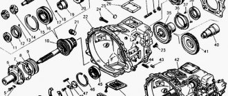
the KamAZ 152 five-speed gearbox includes the following components and parts:
- crankcase , which contains the KamAZ primary, secondary and intermediate shafts;
- block of gears responsible for engaging reverse gear;
- upper gearbox cover;
- collapsible gear shift mechanism ;
- divider mounted on the front of the crankcase.
The KamAZ gearbox, equipped with a gearbox, has a number of positive qualities, including a reduced gear shift frequency, increased traction and simplified vehicle control.
How the checkpoint works
The gearbox of the 152 KAMAZ model has 5 distinctive nuances from the 15th:
- The splines, carriage and gears of the input shaft have been hardened in the DP. The synchronizer clutch was reinforced. The longitudinal size of the gear teeth has become larger.
- The gears are connected to the intermediate shaft using a keyless method.
- The mechanical connection between the secondary shaft and the “synchronizer carriage” part of the 4th and 5th gears no longer requires a locking device.
- To avoid uncontrolled shutdown of 4th and 5th gears, the sizes of the gear teeth and clutches have become larger.
- The diameter of the 4th gear ring has been made larger.
The gear in the design of the intermediate shaft and this element itself cannot be replaced on the 152nd with a similar one from the 15th model. Particular attention should be paid to the marking of spare parts for the truck, the numbers of which start from 152 and above.
Also, transmissions with serial numbers 142 and 152-1700050 are almost completely identical (with the exception of a number of spare parts). The differences are listed below:
- The design of the rear ball bearing cover varies, and there are also noticeable differences in the design of the input shaft;
- There is no ring on the splines in the transmission oil supply system (oil injection). Instead of this unit, a synchronizer clutch is installed in the 152nd box.
- The design of the 142 series includes a front cover of the PrzhV (intermediate shaft). In the 152nd version, it is replaced by a spacer sleeve designed to keep the axial displacement of the ball bearing located at the front within specified limits. The spacer sleeve also serves as an oil slinger.
- The contact between the cavities for the transmission oil of the divider and the gearbox is realized using holes made in the wall of the 1st unit and in the front end of the gearbox.
The primary shaft (PrvV) needs constant adjustment of the axial stroke. For this purpose, the 152nd has gaskets made of durable steel with a thickness of 0.20 or 0.30 mm.
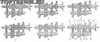
Diagram of operation of a gearbox with a divider
Most KamAZ trucks in use today are equipped with five-speed manual transmissions. The gear shift pattern in such gearboxes is quite familiar: the driver depresses the clutch and moves the lever to the required position. It is important to understand that KamAZ vehicles are heavy-duty trucks, that is, adjusting the position of the lever must be done strictly in stages.
gearbox and divider switching diagram
The typical transmission modes for a truck with a diesel engine are low (“H”) and high (“B”) operating modes. The development of these two options was carried out specifically in order to minimize the load on the engine of the machine, both with a maximum load and when empty. Many KamAZ vehicle models allow you to switch these modes without using the gearshift lever.
The driver just needs to raise or lower a special divider switch and literally squeeze the clutch for a second.
The mode is adjusted automatically: a lowered switch activates a light driving mode, and a raised switch activates a stronger driving mode.
Dealing with switching gearbox modes on KamAZ trucks is relatively simple. To change gears 1-5, use the corresponding lever located to the right of the driver's seat. For example, acceleration of a truck involves the use of the following gear shift pattern: 1B-2B-3B-4Н-4B-5Н-5B . On a clogged highway or in difficult road conditions, use 1H-2H-ЗH-4H-4В-5H-5В .
It should be borne in mind that the KamAZ gearbox device allows you to change speeds only if the clutch is disengaged. To switch from the upper mode to the lower one and vice versa, you need to move the switch to the appropriate position and only then press the clutch all the way and as sharply as possible. Literally in a second you need to release the pedal for the desired main gear to engage.
During the operation of the vehicle, it is very important to monitor how much oil is in the KamAZ gearbox, and, as necessary, add lubricant in a timely manner, preventing possible problems and malfunctions.
Specifications and data
Shaft bearings
When considering this component, it should be noted that depending on where the bearing is used in the shafts, its type changes. The primary shaft of the divider uses ball bearings, and the rear support of the divider shaft uses roller bearings with a missing inner ring. The situation is similar with the gearbox input shaft support.
If the secondary shaft is considered, then a roller bearing is installed in front and a ball bearing in the rear. The intermediate shaft is supported by a roller bearing at the front and a double-row spherical bearing at the rear. Such differences in the bearings used are explained by the technical features of the units, as well as the need to ensure better performance characteristics. With this configuration, the system achieves the greatest stability and reliability.
Synchronizers
The 152 transmission uses inertia synchronizers with brass cone rings installed. All gears, except those used for first gear and reverse, have helical teeth of constant mesh.
During operation, serious friction occurs, which can quickly damage the device. To prevent this problem, a combined lubrication system is used. Each component is lubricated using a spray arm, and a special pressure pump is installed to provide oil flow to the gearbox and splitter bearings. This minimizes friction and damage to the box.
Control
The gearbox is controlled mechanically. Switching of the main box is carried out thanks to a remote drive. The mechanism can be with direct or side exit.
Let's look at the transmission gear ratios:
Gear ratios
- 1H - 7.82
- 1B - 4.03
- 2H - 2.5
- 2B - 1.53
- 3H - 1
- 3B - 7.38
- 4H - 1.53
- 4V - 1.25
- 5H - 1
- 5V - 0.815
- 3ХН - 7.38
- 3ХВ — 6.02
Operating principle of the gearbox synchronizer
Scheme of operation of the synchronizer
When the clutch is turned off, it occupies the middle position, and the gears rotate freely on the shaft. In this case, no torque transmission occurs. In the process of selecting a gear, the fork moves the clutch towards the gear, and the clutch, in turn, moves the locking ring. The ring is pressed against the gear cone and rotates, making further advancement of the clutch impossible.
Under the influence of friction, the speeds of the gear and shaft are synchronized. The clutch moves freely further and rigidly connects the gear and gearbox shaft. The transmission of torque begins and the vehicle moves at the selected speed.
Despite the rather complex structure of the node, the synchronization algorithm lasts only a few fractions of seconds.
4.1. General drive device.
The drive of the brake mechanisms is mixed (pneumohydraulic), dual-circuit, with separate braking of the wheels of the front and two rear axles. The drive consists of two circuits. One circuit operates the brakes of the front axle, the other – the brakes of the rear and middle axles.
Cars have an alarm and emergency brake monitoring system, which consists of warning lamps located on the instrument panel, minimum air pressure sensors in the air cylinders and sensors installed in the pneumatic brake boosters.
Pneumatic brake equipment is used to create a supply of compressed air on the vehicle and to actuate the vehicle brake and trailer brakes.
A piston-type air compressor, non-direct-flow, two-cylinder, single-stage compression, is installed on the flywheel housing in the camber of the cylinder block and is driven by a block of timing gears.
The pressure regulator regulates the pressure of the compressed air supplied by the compressor.
The two-section brake valve is designed to control the actuators of the vehicle's service brake system.
Pneumatic brake boosters with brake master cylinders are mounted on the side member. Pneumatic boosters are designed for a MAX air pressure of 600...800 kPa.
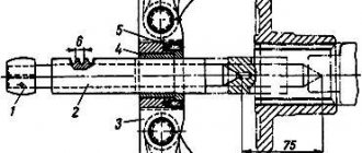
2.1. Valve device.
The steering gear screw passes through the intermediate cover which is attached to the control valve housing. The screw is mounted on two thrust bearings with a spool between them. The valve spool and thrust bearings are secured to the steering gear screw by a nut, the thinned edge of which is pressed into a groove on the screw.
A conical spring washer is placed under the nut to ensure uniform compression of the thrust bearings. The concave side of the washer faces the bearing, the large bearing rings face the spool.
The spool and screw can move in the axial direction by 1...1.2 mm in each direction from the average position, because The length of the spool is longer than the hole for it in the control valve body. It returns to the middle position under the action of springs and reaction plungers, which are under pressure from oil coming from the high pressure line.
Two hoses from the steering pump are connected to the control valve body: a high pressure hose that carries oil from the pump, and a low pressure hose that returns oil to the pump.
There are three annular bores in the hole for the spool of the control valve body. Oil is supplied to the middle bore from the pump. The cavities of the six small holes of the valve body are also connected to the middle bore. Through the two outer bores the oil is returned to the pump. The rear cavity of the amplifier cylinder is connected by channels with a hole for the spool between its front and middle bores.
Design features of KPP-152
After the implementation of new engineering solutions in box 152, its components were no longer suitable for repairing box 15. There is quite a common opinion on the Internet that the transmission of the 15th model can be repaired using components of the 152nd. This position is argued by the fact that the main difference between the systems is the size of the synchronizers and the depth of the splines, but this is not true. An important feature is that paired mechanisms must have all identical parts. Because of this, it is highly not recommended to repair the 15th gearbox with parts 152.
The intermediate shaft and its components from the Model 152 transmission cannot be installed in place of the same parts in the Model 15 transmission.
Such design differences place great demands on the attentiveness of the technician, who must strictly monitor the markings of parts for these two transmission models.
From the point of view of technical design, the 152nd box is most similar to the 142nd model. The differences are in small details that had to be changed to successfully use the gear divider:
- Changing the technical structure of the input shaft and rear bearing.
- Replacement of the front support elements of the input shaft.
- Changing fastening components.
- The oil reflection function is assigned to the spacer sleeve. She replaced the oil injection ring.
- Additional holes appeared between the oil baths in the crankcase.
- To regulate the axial stroke, two steel spacers are used. Their thickness is 0.2 and 0.3 mm, respectively.