During operation of an internal combustion engine, a large amount of heat is generated, some of which is removed by the standard cooling system. Some parts that operate under intense temperature conditions (crankshaft, connecting rods, pins, etc.) are cooled by the oil of the engine lubrication system, which must also release the resulting heat to the surrounding air. The KamAZ liquid-oil heat exchanger (LHT) is designed for these purposes.
How to disinhibit
In order to release the truck from the parking brake, the control handle must be removed from the latch and moved to the lower position.
The control compressed air is supplied via a pneumatic line through an open tap to the accelerator valve, which initiates the supply of the working medium from the receiver through the bypass valve into the lower cavity of the energy accumulator cylinder. The piston moves up and compresses the spring. The brake system rods move to their original position and release the pads. The truck is ready to move. If there is no air in the system or the engine (compressor) breaks down and the vehicle needs to be towed, you must manually release the energy accumulator. To do this, use a socket wrench to remove the screws on the cylinders of all batteries. Thanks to the presence of a thrust bearing, the force will be transferred to the piston, which, while moving, will compress the power spring. Freed from the load, the return spring will move the diaphragm and the rod with the support disk to the upper position. The brake pad drives will return to their original state and unlock the wheels.
Situations often arise during flights when it is necessary to repair a KamAZ energy accumulator with your own hands in the field. The design of the device allows this to be done. However, it will be much easier to replace a defective energy accumulator with a working one and do the repairs in the garage.
Energy accumulator repair
Repair of energy accumulators can be carried out by car service specialists, or, if you have a spare original repair kit, independently.
Causes of battery failure
The list of possible malfunctions is presented as follows:
- mechanical damage or “aging” of the housing, since during operation cavities form on the working surface of the cylinder, which leads to a violation of the chamber’s tightness, making it difficult to repair;
- aging or ruptures of the disk membrane, which indicates the need to sort out the assembly;
- failure of the cover connecting elements.
How to disassemble an energy accumulator
It is better to organize repair of the unit in a service center, but if a malfunction occurs on the road, it is carried out in the field, and the need for disassembly and the sequence of actions remains unchanged. After the unit is removed from the trouser installation site, the order of work is as follows:
- Remove the top part. The air supply hose is moved to the side - this makes it more convenient to remove the rear retaining ring of the pusher after dismantling the thrust bearing. It should not be muted.
- The tap opens the air supply. The pusher plunges, opening access to the retaining ring. The stopper is removed with a homemade hook (it’s convenient for hooking). The groove is cleaned of dirt.
- Close the air supply. Remove the required assembly.
- Of the eight short standard bolts, the covers are unscrewed and four are removed. In their places, long bolts with a locknut and a nut are placed (their size is from 120 mm). Unscrew the remaining four small bolts.
- Gradually releasing the long bolts smoothly releases the working spring. This operating procedure eliminates the need to use special bench devices.
- Replace or restore broken parts. You need to assemble your unit in reverse order.
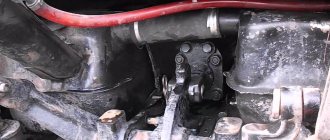
How to release the brakes on an energy accumulator
The emergency wheel locking mode is activated due to a malfunction in the pneumatic system. But repairing or towing the car is possible after manually releasing the energy accumulators that do not work. The following order is provided:
- use a socket wrench to remove the screw;
- excess pressure equalizes atmospheric pressure;
- the thrust bearing transmits force to the piston sufficient to compress the spring and move the diaphragm;
- The rod with the support disk, moving, unlocks the wheels.
https://youtube.com/watch?v=4xLzCQZ9SGA
Replacing the energy accumulator
It is necessary to take care in advance about purchasing a new device, for example, the Turbostar brand. Due to the fact that the units are normally located on bridges, they are replaced at a repair pit. The order is as follows:
- The brake system is relieved of operating pressure.
- The work area on the vehicle is cleaned of dirt and moisture.
- Remove the brake chambers. Unscrew the fastening screws of the old unit, disconnect the air supply hose - the energy accumulator is dismantled.
- It is necessary to carefully place the new unit in its original place and tighten the bolts firmly.
- Included in the high pressure system. The resever is refilled, and the pressure in the pipeline increases.
- They check the quality of the connections and how the system will work by increasing the pressure to operating pressure, followed by repeated release.
How to replace the brake energy accumulator on a MAZ 5432 is presented in the following video:
Adjusting the energy accumulator
If the idle clearance of the chamber rod is exceeded by more than 40 mm, after the bulkhead, a tight fit of the brake pads is not ensured, therefore, it is impossible to reliably hold the car in the parking lot on slopes of the road. In this case, adjustment of the rod stroke is necessary. The condition for its implementation is a disabled brake system and “cold” pads and drums. The sequence of actions is presented as follows:
- loosen the tension of the plug-clamp by a couple of turns;
- turning the axis of the worm mechanism, set the gap - 20 mm;
- fix the position with a stopper;
- the operation is performed with all nodes, the difference in stroke between them should not exceed 3 mm.
How to install
The heat exchanger is assembled after receiving positive results from the defect elimination test. Before installing the device in its original location, it is necessary to prepare the mounting surfaces of the oil system on the filter block. To do this, remove the remains of old seals and clean the flanges. Paronite gaskets are installed with grease and the fastening bolts are tightened. The use of sealant is not recommended.
After installing the LMC in its normal place, it is connected to the engine cooling system. After this, the oil and water cavities are filled with working media. Then the engine is started and the absence of leaks and the operating parameters of the systems being repaired are checked. After the inspection, the heat exchanger repair is considered complete.
Specifications
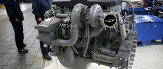
First, it’s worth answering the question - what is KAMAZ? This is a heavy-duty vehicle that has a fairly wide number of body and attachment options. These vehicles are produced by the Kama Automobile Plant. The technical characteristics of the KamAZ-740 engine are quite high. The main domestic competitor of this motor is the products of the Yaroslavl Motor Plant, namely the YaMZ-236/238 model. Although, if you look at it, each of them took their own market niche and stuck to it. The design of the KamAZ-740 engine is even somewhat similar to YaMZ, but a number of design differences can still be traced. So, the Kama engine has a separate cylinder head for each cylinder.
Euro-0 motors marked 740.210 and 740.260
| Name | Characteristic |
| Power | 154 kW. for 210 hp and 191 kW for 260l. With. |
| Type | Diesel |
| Number of cylinders | 8 |
| Number of heads | 8 |
| Number of valves | 16 |
| Cooling | Liquid |
| Volume | 10.85 (10,850 cm3) |
| Power supply system | Injection pump 33 YAZDA or 334 YAZDA |
| Cylinder operating order | 1-5-4-2-6-3-7-8 |
Euro-2 motors marked 740.31-240 and 740.30-260
| Name | Characteristic |
| Power | 176 l. With. for 240 and 191 l. With. for 260 |
| Type | Diesel |
| Number of cylinders | 8 |
| Number of heads | 8 |
| Number of valves | 16 |
| Cooling | Liquid |
| Volume | 10.85 (10,850 cm cube) |
| Power supply system | Fuel injection pump 337-20 YAZDA or 337-21 YAZDA |
| Cylinder operating order | 1-5-4-2-6-3-7-8 |
Euro-2 motors marked 740.51-320 and 740.50-360
| Name | Characteristic |
| Power | 235 l. With. for 320 and 265 l. With. for 360 |
| Type | Diesel |
| Number of cylinders | 8 |
| Number of heads | 8 |
| Number of valves | 16 |
| Cooling | Liquid |
| Volume | 10.85 (10,850 cm cube) |
| Power supply system | Fuel injection pump 337-20-03 YAZDA or 337-20-04 YAZDA |
| Cylinder operating order | 1-5-4-2-6-3-7-8 |
Euro-4 motors marked 740.70 and modifications
| Name | Characteristic |
| Power | 280–420 l. With. |
| Type | Diesel turbocharged |
| Number of cylinders | 8 |
| Number of heads | 8 |
| Number of valves | 16 |
| Cooling | Liquid |
| Volume | 11.67 (11,670 cm cube) |
| Power supply system | Fuel injection pump 337-20-03 YAZDA or 337-20-04 YAZDA |
| Cylinder operating order | 1-5-4-2-6-3-7-8 |
As the characteristics of the KamAZ engine have shown, the power units produced by the Kama Motor Plant are strong enough and capable of providing more power to the truck to transport cargo.
Catalog of LMC models: for which KamAZ trucks are they used?
Heat exchangers for KamAZ diesel engines of the 740 series are either universal or suitable for a specific type of engine.
For example, a long oil heat exchanger for Euro-1 is suitable only for 55111, 65115 and other models with this engine class.
There are several types of universal heat exchangers:
- For Euro 2.3 engine
- For Euro-3.4
- For Euro-2,3,4
Before purchasing a universal LMC, it is necessary to clarify the list of KamAZ models that will fit such a device.
LMCs designed for Euro-2 are suitable for the following models: 6520, 4326, 43115, 53229, 6540, etc.
The Euro 3 heat exchanger is suitable for engines 740.60, 740.61, 740.62 and 740.63. KamAZ models with the following engines: 6520, 5460, 65116 and others.
KamAZ Euro-4 models: 43502,4308, 65116, 65111, 65222, etc.
Heat exchanger KamAZ Euro-1
LMC is used for oil cooling in KamAZ diesel engines. This part can only be found on KamAZ 740 series engines.
The popular truck model 65115 has a Euro-1 environmental class engine, which is equipped with a heat exchanger 740.11-1013200. This LMC is universal and is suitable for any KamAZ 740 engines. This part is a short modification and differs from the other model in the design of the outlet manifold.
Heat exchanger KamAZ Euro-2, 3
The long modification of the heat exchanger 740.20-1013200 differs in the connection method. The hose is secured to the nozzle with a clamp.
This heat exchanger is suitable for Euro-2, Euro-3 engines. It is used on various models of trucks with engines of this class, for example, the KamAZ 6520 dump truck.
If malfunctions occur, the question arises of how to remove the LMC. First of all, you need to drain the coolant and disconnect it from the power source. Next you need to loosen the clamp and other fixing elements.
Weak spots
Every car cooling system has some weak points. The most common problems in KAMAZ include:
- occurrence of leaks;
- increase in antifreeze temperature to unacceptable levels;
- supercooling of the coolant;
- penetration of antifreeze into the oil system.
Important Maintenance of brake pads on KamAZ vehicles
Antifreeze leaks in KAMAZ most often occur at the junction of the pipes. Sometimes this problem occurs due to cracking of rubber hoses. System overheating occurs when the antifreeze level drops sharply. In this case, it is not able to ensure efficient operation of the engine.
Overheating or excessive cooling of the liquid can occur when thermostats fail. It all depends on the position of the valve, which gets stuck, which causes problems. When the thermostat is open, antifreeze is constantly circulating. This prevents the engine from heating up and starting (this is especially noticeable when the blinds are open). When the thermostat is closed, antifreeze does not flow to the radiator, where it cools. Therefore, the coolant in KAMAZ quickly overheats.
Another weak point is the fan and clutch. If it doesn't work efficiently, the engine won't be able to cool enough. Therefore, to prevent problems from occurring, it is necessary to constantly monitor the condition of KAMAZ and promptly eliminate all problems.
Flushing the engine cooling system can be done in several ways. If minor contamination is detected, ordinary water can be used for this. To do everything correctly, you need to completely drain the antifreeze. Instead, plain water is pumped into the tubes. After this, start the engine, which should warm up at idle speed. The water is drained and everything is repeated several times until the unit can be completely cleaned.
If significant contamination is detected, it is best to use special flushing liquids. It can be added to the tubes without draining the antifreeze, after which it is removed along with it. But experts recommend using solutions that are poured into an empty system.
The KAMAZ engine radiator is always washed separately, using special liquids. This ensures a more thorough cleaning. In this case, experts recommend using a weak solution of hydrochloric acid.
Additional recommendations for performing high-quality rinsing
To perform high-quality flushing, you should not forget that the supply of cleaning liquid must occur in the opposite direction to the movement of antifreeze. It is especially effective to do this using special equipment that creates additional pressure.
To drain the coolant in a KAMAZ, you need to open all the valves - radiator, heat exchanger, pump, antifreeze supply pipes. Be sure to unscrew the expansion tank cap. The taps are closed only after the liquid has completely drained.
Repair
The main malfunctions of the heat exchanger are loss of tightness of the tube bundle and a decrease in the power of the device due to silting of the flow part of one or both cavities. In case of such breakdowns, the functionality of the device is restored by cleaning, welding or plugging the tubes. However, sometimes defects arise when their elimination is impractical. In such a situation, an aggregate replacement of liquid metal parts is carried out.
In most cases, a leak in a pipe system occurs in the area where the heat exchange tubes are attached to the end flanges. Signs of a leak are the appearance of an oil suspension in the engine cooling system. The locations of detected defects are sealed. If the fistula appears in the tube itself, then it is plugged. No more than 10% of the cooling elements are allowed to be taken out of service. After the malfunction is eliminated, the heat exchanger is pressurized, thereby checking the quality of the work performed.
In most cases, descaling of tubes is carried out mechanically using a roller cutter or special screw attachments installed in a drill. If it is impossible to clean the liquid solids in this way, chemical washing is carried out using washing liquids. To do this, use a 5% aqueous solution of hydrochloric acid. The core is soaked in it and left in this state for 30-40 minutes. After this, the part is thoroughly washed in a 3% sodium bicarbonate solution.
Cleaning is carried out until the dirt is removed. After this, the core is washed with hot water and dried well (blown with air).
Many drivers believe that if the device loses its tightness or leaks in the tubes, the heat exchanger needs to be replaced with a working one, because After some time, the same defect occurs again.
During any disassembly of LMC, it is necessary to install only new gaskets.
Principle of operation
The operating principle of a condensation-based dehumidifier is based on the physical process of condensation, when moisture turns into a liquid state due to the contact of air with a cool surface. A condensation dryer works as follows:
- Using a fan, air is forced into the device body.
- In the housing, the air passes through two series and connected heat exchangers.
- When passing through the first heat exchanger with a low surface temperature, moisture condenses from the air. It collects on the surface of the heat exchanger and flows into the condensate collection tank.
- When filling the container, excess is removed from the device using a drainage tube.
- Condensation occurs due to the transfer of temperature from air to freon, the refrigerant actively evaporates.
- The evaporated freon from the first heat exchanger enters the compressor.
- From the compressor, freon is supplied to the condenser (second heat exchanger).
- Cooled air, when passing through the second heat exchanger, condenses freon. The air receives heat and heats up.
Operating principle of a condensation dehumidifier using the example of the “DH TIM 20 E1B” model
The main disadvantage of a condensing device is the increase in outlet temperature. The temperature change can be about 5 degrees. If for objects with a large area such heating is not critical, then for small rooms it can create serious inconveniences.
An adsorption dryer carries out the process of removing moisture due to the physical process of adsorption, that is, the concentration of dissolved moisture and its absorption by the adsorbent. In a device operating on this drying principle, the following processes occur:
- The fan draws air into the device through a special lattice opening.
- Humid air passes through the rotor blades, which are filled with silica gel. The adsorbent absorbs moisture from the air.
- The dried air passes further and is removed from the device. After passing through the rotor, part of the air is discharged through a special channel back to the rotor. It passes through the heater and returns to the rotor blades. Passing through a rotating element with moistened silica gel, the air provokes the desorption process (the process of reverse removal of moisture from the adsorbent). The released moisture in a liquid state enters the heat exchanger and is discharged into a condensate container.
Such dehumidifiers require serious maintenance on an ongoing basis. In addition, they are quite expensive.
Flushing the cooling system
There are different ways to flush the cooling system. In case of minor contamination, you can rinse with plain water. To do this, the old coolant is drained and water is added instead. The engine starts and warms up at idle speed. After this, the water is drained and the entire cycle is repeated several times until completely cleaned.
If the contamination in the system is significant, it is best to use special ready-made flushes. At the same time, there are quick options when flushing is simply added to the old antifreeze, and then everything is drained. But it is better to use flushing solutions when the old coolant has already been drained. It should also be taken into account that to clean the engine water jacket, the cleaning solutions will be different. The cooling system radiator should be flushed separately for more effective cleaning. A 2.5% hydrochloric acid solution has worked well for this.
One of the features of flushing should be known that the direction of the flushing flow should be opposite to the normal flow of the coolant. It will be more effective to flush the system with a stream of water or a chemical solution under pressure.
Replacing the KAMAZ oil filter
Necessary materials, tools: head “17”, container for draining waste (40 liters), rags. Before changing the engine oil, warm up the internal combustion engine to an operating temperature of 40°.
- installing the machine above the inspection channel;
- driver's cab tilt;
- unscrewing the filler plug;
- unscrewing the drain plug from the oil pan;
- grinding the waste into containers;
- unscrewing the rod of the coarse filter housing;
- similar actions with a fine filter;
- removing oil filters;
- replacing rubber seals;
- laying new MFs;
- cylinder insertion, screwing;
- filling mineral-based engine oil (36.8 liters);
- cab lowering;
- starting the power unit;
- checking the engine oil level. Top up as needed.
This completes the process of replacing the MF with your own hands. Scheduled maintenance after 20 thousand km.
Access to the MF is from under the bottom of the vehicle, as well as through the top of the frame when the cab is overturned. Choose the most appropriate option for prevention and diagnosis. Check the condition of the fuel cleaner, install new ones as necessary.
Important: Varyag petrol and diesel walk-behind tractors
Installation
If the moisture separator is completely out of order, it must be replaced with a new device. If desired, you can perform the installation procedure for a fresh unit yourself.
To ensure a high-quality installation of the device, you will need to first prepare the following tools and materials:
- personal protective equipment: mask and goggles;
- wrench;
- screwdriver;
- welding machine for adjusting the size of pipes;
- hammer.
To carry out the procedure, the car owner should:
- Place the car on a flat surface, having previously fixed its position.
- Remove the vehicle bracket using the appropriate tool.
- Unscrew the fixing bolts holding the radiator housing.
- Remove the O-rings and gasket, depressurizing the system yourself.
- Screw the device to the frame using mounting bolts.
- Connect the pipe from the compressor to the moisture separator.
- Check the tightness of the membrane.
- Inspect the condition of the valves and replace them if necessary.
- Check the pressure level and compression ratio of the air flow entering the system.
- Install the sealing rings and filter element.
- Return the top cover to its place and secure it with bolts.
The last step is to reassemble the mechanism. Installation of equipment can only be carried out in a vertical position, and care should be taken to ensure that the position of all elements is securely fixed and secured.
You can check the functionality of the mechanism by turning on the engine. If the motor operates properly and no unpleasant sounds occur during operation, it means that the repair was performed correctly. If problems are found in the operation of the device, it is recommended to seek help from service center specialists.
A moisture separator is a special device that promotes safe and comfortable operation of a truck.
Service
Maintenance of a liquid-oil heat exchanger involves promptly flushing the part from contaminants. During operation, sediment appears that clogs the core. Gaskets and connecting elements also wear out, which leads to loss of tightness.
All these malfunctions lead to overheating of the engine and a decrease in its power.
Regular maintenance with dismantling the heat exchanger will help extend the life of the device. It is necessary to clean the space between the plates from sediment, regularly change the gaskets, and, if necessary, replace the core. It is very important to use high-quality oil recommended by the manufacturer. During any work on the heat exchanger, the coolant must be drained.
Malfunctions and repairs
The cause of the water pump malfunction is the loss of tightness of the mechanical seal. After hot coolant enters the cavity of the bearings, the lubricant is washed out of the latter. After a while the pump starts to rattle and then jams. Self-diagnosis allows you to identify such a defect by antifreeze leakage from the control hole, shaft play, and in winter - by a decrease in the efficiency of the cabin heater.
Restoring the pump's functionality can be done through a unit replacement. But most drivers repair the KamAZ pump with their own hands. If the spare parts kit contains the necessary parts or the shaft assembly, then repairing the pump is not difficult at all. To do this, it is necessary to remove the pump from its original location, disassemble and replace defective parts. A distinctive feature of the KamAZ Euro water pump is that the blower fan is mounted not on the pump pulley, but on a fluid coupling.
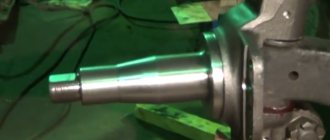
How to remove and disassemble
Dismantling the pump is not difficult. Before starting work, it is necessary to drain the coolant. It must be remembered that antifreeze is toxic and can harm the environment. Therefore, it needs to be collected in a container. Clean coolant after filtration can be reused. To remove the drive belts, you need to loosen their tension. After draining the coolant, remove the clamps securing the antifreeze supply pipes.
The pump is attached to the block with 3 bolts. Having unscrewed them, remove the pump assembly from its regular place and take it out along with the coolant supply pipes to the thermostat and fluid coupling. To disassemble the water pump, remove the pulley and impeller fasteners. To remove the shaft with bearings and seal, use a drift made of soft material. If necessary, disassemble the defective unit and install functional parts from the repair kit.
How to change
KamAZ trucks use pumps with single- and double-strand pulleys. If there is a need for a unit replacement, then you need to buy a pump that is a complete analogue of the previously installed one. Otherwise, there is a high probability of a repeat defect. The pump is replaced in the reverse order of removal. Before installing it, it is necessary to fill the cavity of the bearing unit with grease until the latter appears in the control hole. This will make it difficult for antifreeze to enter if the seal breaks.
How to remove and disassemble
To carry out scheduled maintenance or eliminate a defect, the liquid metal parts must be dismantled. It is difficult to remove the heat exchanger on a KamAZ truck with your own hands, but it is possible. To do this, it is necessary to dismantle the components that interfere with free access to the device. Then the water pipes are disconnected and only after that the oil pipes. All openings on the engine are covered with a clean rag to prevent dirt from getting into the cavities.
Disassembling the heat exchanger involves dismantling the core for subsequent cleaning or eliminating defects that have arisen. After dismantling, be sure to remove it, and if that doesn’t work, scrape off the old paronite gaskets from the flanges. It must be remembered that there may be antifreeze left in the tubes, and oil residues in the housing. The removed heat exchanger is inspected for cracks and contamination of the cooling surface.
Due to the fact that the LMC body is made of aluminum, it is not recommended to use a hammer during dismantling.
Device
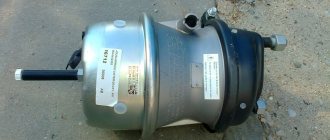
The spring accumulator is mounted on the brake chamber cover and serves to accumulate the energy of the compressed spring.
The main parts of the device are:
- cylinder;
- piston;
- power spring;
- pusher;
- thrust bearing;
- release screw with roller bearing;
- bypass tube;
- seals.
The battery is attached to the camera using bolts, which ensures a strong connection and eliminates play during operation. The seal between the cylinder and the brake chamber is ensured by installing a rubber sealing ring. A nut for the screw of the brake release system is welded in the upper part of the housing. At the bottom of the cylinder there is a threaded fitting through which the pneumatic line is connected.
A tubular pusher is welded to a metal piston with a rubber sealing ring. The steel power spring is located in the piston groove and rests on the top of the cylinder. The pusher has a thrust bearing, which transmits force to the brake chamber rod through a membrane.
The screw is used for manual release in the event of a lack of compressed air in the system due to a compressor failure or a defective receiver. At the bottom of the screw there is a roller bearing and 2 thrust rings.
The cavity located above the piston communicates with the atmosphere via a bypass tube through the brake chamber. Air is supplied to the chamber under the piston from the parking brake control valve. All energy accumulators simultaneously participate in air analysis.
How does oil circulate in the oil system of the KamAZ-740 engine?
Oil from the sump flows through an oil receiver with a strainer into the oil pump sections. From the discharge section, oil is supplied through a channel to a full-flow filter, and from there to the main oil line. Then, through channels in the block and cylinder heads, oil under pressure is supplied to the crankshaft and timing parts, fuel injection pump and compressor. Oil is supplied to the connecting rod bearings through the crankshaft channel from the main journal closest to them. The supports of the rods and pushers of the gas distribution mechanism are washed by a pulsating jet, and the remaining parts are washed by splashing or gravity flow of oil. Oil removed from the cylinder walls by oil scraper rings is discharged through drillings in the piston grooves into the piston and lubricates the piston pin supports in the upper connecting rod head and piston bosses. From the main lubrication line, oil under pressure is supplied to the thermal power sensor, and when the fluid coupling valve is open, it is supplied to the fluid coupling itself. From the radiator section of the oil pump, oil is supplied to the centrifugal (fine) filter and through the open oil cooler valve to the radiator itself, and from it to the engine sump. If the oil cooler switch valve is closed, then oil flows from the centrifuge (centrifugal filter) into the sump through the drain valve. Insufficient oil supply to the rubbing parts of the engine causes loss of power, increased wear of parts, overheating and melting of the sliding bearings, jamming of the pistons and, ultimately, cessation of engine operation.
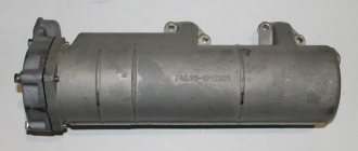
What does a liquid-oil heat exchanger consist of and how does it work?
Inside the body of the aluminum part there is a core with a deflector and oil filters, from which inlet and outlet pipes for pumping coolant extend. The inlet pipe (manifold) is responsible for supplying coolant from the cylinder block for cooling, and the outlet pipe is responsible for returning the coolant back to the water jacket. Also, an important design element is a bypass valve for emergency operation bypassing the deflector in case of clogging or other problems in operation.
The core is divided by metal plates into 4 isolated sections. Their presence allows you to direct the flow of oil and coolant inside the operating system. This is also what the flange does, tightly fixed inside the housing with o-rings at one end and resting against the end wall at the other. The deflector is responsible for directing the flow of engine oil in the design.
Despite all the apparent complexity, the main task of the part is to effectively separate the oil and refrigerant flows when distilling them inside a closed loop. Accordingly, the refrigerant is “locked” inside the core tubes, and the oil, which needs more space and flow path, seeps between the tubes with the refrigerant and the walls of the LMC housing. The inlet manifold is connected to the system through a short adapter tube, and the outlet manifold is connected by clamping.
The operating principle of a liquid-oil cooler in general looks like this:
when the engine heats up to 95–100 degrees, the thermal power valve of the LMC opens;
through the valve, part of the oil from the filters enters the casing;
inside, the oil passes through all 4 core blocks, giving off heat and cooling in the process;
the cooled oil gradually returns to the system through the outlet manifold.
If the engine overheats to 100–115 degrees, the entire oil flow from the system passes through the heat exchanger. LMC is effective at engine heating temperatures up to 115 degrees. In case of overheating, an emergency indicator starts flashing on the KAMAZ dashboard, signaling the need to turn off the engine until it cools completely and perform diagnostics of the system to find the reason for reaching a critical temperature level.
Troubleshooting
The cooling system (KAMAZ 5320) must operate without deviations from inspection to inspection. But cases are different and malfunctions can arise unexpectedly. Knowing the weaknesses of the system will help you quickly identify the problem and solve it on the spot.
Important Technical characteristics of the GAZ-SAZ-3507 dump truck and its main modifications
Violation of the tightness of the system is solved by finding the location of the leak and, if possible, eliminating it. A visual inspection is often sufficient for this purpose. All connections, water pump, radiator, coupling are checked. In this case, it is better to simply replace worn pipes. Radiator leaks can be eliminated by soldering or plugging leaky pipes. The decision to replace the radiator is made individually, because it is quite repairable and can be washed well when removed.
When detected, wear or delamination of the drive belt is best resolved by replacement. If there is a suspicion that the thermostats are not working properly, then it is convenient to check them by heating the lower radiator tank. At a temperature of 850C, that is, when the thermostat valve begins to open, the tank should warm up. If this does not happen, the valve is faulty and the thermostat should be replaced.
The cooling system (KAMAZ Euro 2) is no different from its earlier versions and later ones too. The problems that may arise in the cooling system are the same in their symptoms. One of these malfunctions is the ingress of coolant into the lubrication system. It can be detected by the decrease in antifreeze without traces of leakage. The cause may be worn cylinder head gaskets, as well as leaks through block liner seals. The problem is solved by replacing worn engine gaskets.
What is a KAMAZ oil heat exchanger?
Масляный теплообменник (liquid-oil heat exchanger, LMT) - a unit for lubrication and cooling systems of high-power diesel power units; a heat exchanger of a special design built into the engine liquid cooling system that provides cooling of the engine oil due to heat exchange with the coolant flow.
The lubrication system of powerful KAMAZ diesel units operates in difficult conditions; the oil is constantly exposed to high temperatures and gradually loses its quality. In certain modes, engine oil may overheat, which leads to a decrease in its viscosity and lubricity, as well as to intense decomposition and burnout. Ultimately, overheated oil impairs engine performance and can even cause engine failure. This problem is solved by introducing an element for oil cooling - a heat exchanger - into the lubrication system of KAMAZ engines.
The oil heat exchanger is an integral part of the engine lubrication and cooling systems; it ensures the removal of excess heat from the oil due to active heat exchange with the washer flow of coolant (coolant). That is why devices of this type are called liquid-oil heat exchangers, or LHT. This unit performs several functions:
- Partial oil cooling at engine temperature less than 100 degrees;
- Cooling of all oil supplied to the engine at a temperature within 100-110 degrees;
- Reducing oil consumption due to waste and extending its service life;
- Ensuring optimal temperature conditions for various engine systems - thanks to liquid coolant, the oil temperature never drops below the coolant temperature, which contributes to more uniform heating of engine parts, reduction of mechanical stress, etc.;
- Simplifying the design of the oil cooling system and reducing the cost of the engine while ensuring normal performance characteristics.
Today, heat exchangers are installed in most KAMAZ diesel engines that comply with Euro-2 standards and higher; they play an important role in ensuring normal characteristics of the power unit in all operating modes. A faulty heat exchanger needs to be repaired or completely replaced as soon as possible, but before buying a new part, you should understand the design and operation of these devices.
This is interesting: How to correctly calculate how many cubes of concrete will go into a KamAZ mixer
Why malfunctions occur in the KamAZ heat exchanger
The main malfunction that can happen to the heat exchanger is mixing of coolant and oil. Such a problem can damage the entire engine, because the cooling system will be disrupted, and in addition, the oil will lose its lubricating properties, which will lead to rapid wear of parts.
The problem arises due to depressurization of any section of the heat exchanger: loose connections of tubes, cracks in the body, breakdown of gaskets, incorrect adjustment of valves.
The problem can be detected by some indirect signs:
- The engine began to overheat
- Engine lubrication pressure decreases due to the fact that the mixture of oil and coolant is very dense and clogs the filters
- Coolant color changes
Overhaul: basic provisions
Overhaul of the KamAZ-740 engine is a rather complex procedure that requires knowledge of the design, technical standards and special equipment to carry out these operations. There are instructions for overhauling power units that were developed by the manufacturer.
Of course, not all car services that specialize in repairing internal combustion engines adhere to this, but they quite clearly and accurately describe all the subtleties and nuances of the process.
Let's consider the sequence of actions aimed at carrying out restoration operations on the KamAZ-740 engine:
- First, the faulty motor is disassembled to determine defects.
- The next step is fault diagnosis. This includes diagnostic work on the crankshaft, cylinder heads, which are placed one for each cylinder, as well as the camshaft, water and oil pumps. Separately, it is worth noting that when carrying out major repair and restoration work on the engine, work is required to restore the high-pressure fuel supply pump.
- The next stage of power unit repair is boring the block and crankshaft. It is worth noting that the KamAZ crankshaft is a fairly strong part, so turning the journals is not always required. But with the block, as practice shows, things are much worse. In any case, you will have to bore the cylinders, but this does not always help. So, if the engine is 20 years old, then, as experts say, there is nothing left to sharpen, and the only solution is to line the block. Of course, this procedure increases the cost of repairs, but it is cheaper than buying a new cylinder block. Let's consider the repair dimensions of the parts.
| Name/Repair | Repair 1 | Repair 2 | Repair 3 | Repair 4 |
| Crankshaft | 0.25 mm | 0.50 mm | 0.75 mm | 1.00 mm |
| Cylinder block | 120.5 mm | 121.0 mm | 121.5 mm | ST - sleeve |
- An integral stage of engine restoration is the repair of all heads, of which KamAZ has eight. Thus, guide bushings are often changed, which are first turned on a lathe. The valves are chamfered and adjusted, and the seats are subjected to a roller cutter.
- The next step is polishing the camshaft cams. This is done on a lathe using a special paste and sandpaper.
- Next comes the stage of repairing the water and oil pump. As practice shows, engine repair specialists are reluctant to repair these parts, but due to their particular high cost, they have to in order to retain customers. As mentioned earlier, only some elements of the products can be replaced. So, the impeller, shaft assembly, cuff and bearings are replaced.
- Before you begin the crankshaft installation procedure, it is necessary to carry out the balancing process. The clutch is attached to the crankshaft and rotated, installing special weights. If this procedure is not carried out, then during operation the shaft will become unbalanced, which will lead to breakage of the yokes and connecting rods with liners.
- The last stage can rightfully be considered assembly. This process is quite long as it takes almost the whole day. The crankshaft is laid down and goes through the “banding” process. This is the procedure for connecting the crankshaft to the piston group and installing the liners, both main and connecting rod. Next, the oil pump and pump are assembled. All small parts are collected. The last to be installed are the cylinder heads, valve covers, injection pump and exhaust system.
- After the engine is assembled, it needs to be run in. This is done only when it is hot. The power supply system and exhaust system are connected to the power unit, and then it is started, adjusting the speed, and the valve clearances are periodically set.
After the KamAZ power unit is assembled, it is installed on the vehicle and tested on the move.
This is interesting: How to correctly set the ignition on KAMAZ trucks: we study the issue