Not available:
| № | Part code | Name | Part Information |
| 1-1-85x110-4 | Cuff | Quantity for DT-75N 2 | Not available |
| 10-65G | Washer GOST 6402-70 | Quantity for DT-75N 18 | Not available |
| 112-39-013 | Oil seal housing | Quantity for DT-75N 2 | Not available |
| 112-39-119 | Ring | Quantity for DT-75N 2 | Not available |
| 112-39-125 | Thrust washer | Quantity for DT-75N 2 | Not available |
| 112-39-126 | Washer | Quantity for DT-75N 2 | Not available |
| 112-39-131 | Oil seal housing | Quantity for DT-75N 2 | Not available |
| 12-65G | Washer GOST 6402-70 | Quantity for DT-75N 20 | Not available |
| 12T-65G | Washer GOST 6402-70 | Quantity for DT-75N 20 | Not available |
| 14T-65G | Washer GOST 6402-70 | Quantity for DT-75N 20 | Not available |
| 16T-65G | Washer GOST 6402-70 | Quantity for DT-75N 24 | Not available |
| 18T-65G | Washer GOST 6402-70 | Quantity for DT-75N 4 | Not available |
| 1B190 | Ring GOST 13941-68 | Quantity for DT-75N 2 | Not available |
| 20T-65G | Washer GOST 6402-70 | Quantity for DT-75N 14 | Not available |
| 32315KM | Radial roller bearing with short rollers (75Х160Х37) | Quantity for DT-75N 2 | Not available |
| 32318KM | Radial roller bearing with short rollers (90Х190Х43) | Quantity for DT-75N 2 | Not available |
| 413 | Single row radial ball bearing (65Х160Х37) | Quantity for DT-75N 2 | Not available |
| 55-32-026 | Seal spring assembly | Quantity for DT-75N 2 | Not available |
| 55-32-158A | Seal ring | Quantity for DT-75N 2 | Not available |
| 55-32-161 | Seal cover | Quantity for DT-75N 2 | Not available |
| 55-32-163 | Pressure washer | Quantity for DT-75N 4 | Not available |
| 62314KM | Bearing | Quantity for DT-75N 2 | Not available |
| 77-37-203 | Plug gasket | Quantity for DT-75N 2 | Not available |
| 77-38-102 | Rear axle shaft | Quantity for DT-75N 2 | Not available |
| 77-38-107A | Ring sealing | Quantity for DT-75N 2 | Not available |
| 77-39-001 | Final transmission right | Quantity for DT-75N 1 | Not available |
| 77-39-002 | Final transmission left | Quantity for DT-75N 1 | Not available |
| 77-39-011-1 | Driven gear with hub assembly | Quantity for DT-75N 2 | Not available |
| 77-39-012A | Drive wheel shaft assembly | Quantity for DT-75N 1 | Not available |
| 77-39-014 | Seal housing assembly | Quantity for DT-75N 2 | Not available |
| 77-39-015-1B | Plug with magnet assembly | Quantity for DT-75N 1 | Not available |
| 77-39-016-1 | Plug with magnet assembly (with left-hand thread) | Quantity for DT-75N 1 | Not available |
| 77-39-017-1 | Cover with breather assembly | Quantity for DT-75N 2 | Not available |
| 77-39-019 | Drive wheel shaft | Quantity for DT-75N 2 | Not available |
| 77-39-020 | Drive wheel shaft | Quantity for DT-75N 2 | Not available |
| 77-39-027Р | Support | Quantity for DT-75N 1 | Not available |
| 77-39-031 | Final transmission left | Quantity for DT-75N 1 | Not available |
| 77-39-032 | Final transmission right | Quantity for DT-75N 1 | Not available |
| 77-39-101B | Final drive housing right | Quantity for DT-75N 1 | Not available |
| 77-39-103 | Cover right | Quantity for DT-75N 1 | Not available |
| 77-39-103B | Final drive housing left | Quantity for DT-75N 1 | Not available |
| 77-39-104 | Cover left | Quantity for DT-75N 1 | Not available |
| 77-39-105 | Final Drive Cover Gasket | Quantity for DT-75N 2 | Not available |
| 77-39-106A | Lid | Quantity for DT-75N 2 | Not available |
| 77-39-107-1A | Drive gear | Quantity for DT-75N 2 | Not available |
| 77-39-107-2 | Drive gear | Quantity for DT-75N 2 | Not available |
| 77-39-108 | Driven gear hub | Quantity for DT-75N 2 | Not available |
| 77-39-109V | Bolt is tight | Quantity for DT-75N 16 | Not available |
| 77-39-109V | Bolt is tight | Not available | |
| 77-39-109VR | Bolt | Quantity for DT-75N 16 | Not available |
| 77-39-111B | Lock washer | Not available | |
| 77-39-112A | Pin | Quantity for DT-75N 2 | Not available |
| 77-39-112Р | Pin | Quantity for DT-75N 2 | Not available |
| 77-39-115A | Safety lining | Quantity for DT-75N 2 | Not available |
| 77-39-116B | Bearing cup | Quantity for DT-75N 2 | Not available |
| 77-39-117-1A | Support | Quantity for DT-75N 2 | Not available |
| 77-39-118 | Bearing cup gasket | Quantity for DT-75N 2 | Not available |
| 77-39-119A | Yoke | Quantity for DT-75N 1 | Not available |
| 77-39-120 | Locking plate (1.4 mm) | Quantity for DT-75N 4 | Not available |
| 77-39-121 | Adjusting gasket | Quantity for DT-75N 4 | Not available |
| 77-39-121-01 | Adjusting gasket | Quantity for DT-75N 8 | Not available |
| 77-39-122 | Final drive housing gasket | Quantity for DT-75N 2 | Not available |
| 77-39-123 | Special washer | Quantity for DT-75N 2 | Not available |
| 77-39-124-1 | Driven gear | Quantity for DT-75N 2 | Not available |
| 77-39-125 | Lock washer | Quantity for DT-75N 2 | Not available |
| 77-39-128 | Washer | Quantity for DT-75N 2 | Not available |
| 77-39-132 | Wheel | Quantity for DT-75N 2 | Not available |
| 77-39-132A | Drive wheel | Not available | |
| 77-39-133A | Pin | Quantity for DT-75N 2 | Not available |
| 77-39-133Р | Pin | Quantity for DT-75N 2 | Not available |
| 77-39-134 | Seal body | Quantity for DT-75N 2 | Not available |
| 77-39-135 | Ring sealing | Quantity for DT-75N 2 | Not available |
| 77-39-137 | Pad | Quantity for DT-75N 2 | Not available |
| 77-39-138 | Round nut | Not available | |
| 77-39-141A | Visor | Quantity for DT-75N 2 | Not available |
| 77-39-142 | Seal ring | Quantity for DT-75N 2 | Not available |
| 77-39-143 | Oil seal housing gasket | Quantity for DT-75N 2 | Not available |
| 77-39-144 | Cover gasket | Quantity for DT-75N 2 | Not available |
| 77-39-145 | Seal housing gasket | Quantity for DT-75N 2 | Not available |
| 77-39-148-1 | Special yoke washer | Quantity for DT-75N 2 | Not available |
| 77-39-149 | Black washer | Quantity for DT-75N 8 | Not available |
| 77-39-151 | Yoke | Quantity for DT-75N 1 | Not available |
| 77-39-158 | Special bolt | Quantity for DT-75N 4 | Not available |
| 77-39-158 | Special bolt | Quantity for DT-75N 2 | Not available |
| 77-39111B | Washer | Quantity for DT-75N 8 | Not available |
| 77-52-268 | Ring | Quantity for DT-75N 2 | Not available |
| 77-55-128 | Ring sealing | Quantity for DT-75N 2 | Not available |
| A41-31 | Spring ring | Quantity for DT-75N 2 | Not available |
| K01-6 | Wire (0.16 m) | Not available | |
| KG3/8 | Cork | Quantity for DT-75N 2 | Not available |
| М10-6gх25 | Bolt | Quantity for DT-75N 4 | Not available |
| М10-6gх45 | Bolt | Quantity for DT-75N 14 | Not available |
| М12-6gх100 | Bolt | Quantity for DT-75N 2 | Not available |
| М12-6gх130 | Bolt | Quantity for DT-75N 2 | Not available |
| М12-6gх140 | Bolt | Quantity for DT-75N 2 | Not available |
| М12-6gх30 | Bolt | Quantity for DT-75N 8 | Not available |
| М12-6gх35 | Bolt | Quantity for DT-75N 24 | Not available |
| М12-6gх60 | Bolt | Quantity for DT-75N 2 | Not available |
| М14-6gх55 | Bolt | Quantity for DT-75N 20 | Not available |
| М16-6gх130 | Bolt | Quantity for DT-75N 4 | Not available |
| М16-6gх32 | Bolt | Quantity for DT-75N 2 | Not available |
| М16-6gх35 | Bolt | Quantity for DT-75N 6 | Not available |
| М16-6gх45 | Bolt | Quantity for DT-75N 4 | Not available |
| М16-6gх60 | Bolt | Quantity for DT-75N 18 | Not available |
| М16-6gх75 | Bolt | Quantity for DT-75N 6 | Not available |
| M16x1.5-6N | screw | Quantity for DT-75N 16 | Not available |
| M18x1.5 | screw | Quantity for DT-75N 4 | Not available |
| М20-6gх70 | Bolt | Quantity for DT-75N 12 | Not available |
| M20x1.5-6gx45 | Bolt | Quantity for DT-75N 2 | Not available |
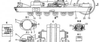
Final transmission - DT-75N:
1.1-85x110-4 10.65G 10.65G 112.39.013 112.39.119 112.39.125 112.39.126 112.39.131 12.65G 12T.65G 12T.65G 12T.65G 14T.65G 16 T.65G 16T.65G 18T.65G 1B190 20T. 65G 20T.65G 32315KM 32318KM 413 55.32.026 55.32.158A 55.32.161 55.32.163 62314KM 77.37.203 77.38.102 77.38.107A 77.39.001 7 7.39.002 77.39.011-1 77.39.012A 77.39.014 77.39.015- 1B 77.39.016-1 77.39.017-1 77.39.019 77.39.020 77.39.027R 77.39.031 77.39.032 77.39.101B 77.39.103 77.39.103B 77.39.104 77. 39.105 77.39.106A 77.39.107-1A 77.39 .107-2 77.39.108 77.39.109В 77.39.109В 77.39.109ВР 77.39.111Б 77.39.112А 77.39.112Р 77.39.115А 77.39.116Б 77.39.117-1А 77.3 9.118 77.39.119A 77.39.120 77.39.121 77.39. 121-01 77.39.122 77.39.123 77.39.124-1 77.39.125 77.39.128 77.39.132 77.39.132A 77.39.133A 77.39.133R 77.39.134 77.39.135 7 7.39.137 77.39.138 77.39.141A 77.39.142 77.39.143 77.39.144 77.39.145 77.39.148-1 77.39.149 77.39.151 77.39.158 77.39.158 77.39111B 77.52.268 77.55.128 A41-31 K01.6 K G3/8 M10.6gx25 M10.6gx45 M12 .6gx100 M12.6gx130 M12.6gx140 M12.6gx30 M12.6gx35 M12.6gx35 M12.6gx60 M12.6gx60 M14.6gx55 M16.6gx130 M16.6gx32 M16.6gx35 M16.6gx45 M16.6 gx60 M16.6gx75 M16.6gx75 M16x1.5.6 N M18x1.5 M20.6gx70 M20x1.5.6gx45
List of components from Final transmission to DT-75N
Parts diagrams are for reference purposes only! We do not sell all spare parts for the final transmission for the DT-75N presented in this list. If there is a “Show prices” link in the right column, these spare parts from “Final Transmission” are on sale. Availability in warehouses for details and prices, see the product card. If there is no “Show cost” link in the right column, we do not sell such parts and do not accept orders for them.
| № | Part code | Name | Part Information | Show all prices |
4.22.
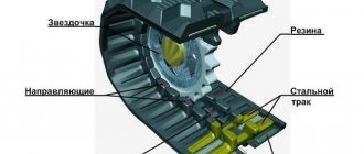
Track chain of the DT-75N tractor
The tractor is equipped with universal track chains that provide traction in icy conditions and safety of the tractor on a side slope in summer and winter.
The design of the universal links includes a wear reserve of 8-10 mm for the eyes and 15-16 mm for the lanterns, which ensures high durability of the tracks with timely multiple replacement of pins and use of the links until they are completely worn out.
Rice. 65. Track target 1 - track link; 2 - finger; 3 — washer; 4 cotter pin
The track chain consists of links 1 (Fig. 65), hingedly connected to each other by fingers 2.
The fingers are inserted into the holes of the links' eyes and are kept from falling out on the outside by stamped heads, and on the inside by cotter pins 4 and washers.
The track link is a steel casting of complex configuration, having seven eyes: four on one side and three on the other. The middle of the central eye is thickened on the outer side and is a lantern designed to engage with the teeth of the drive wheel. On the inner surface of the chains, the links have running tracks along which the support rollers of the suspension carriages roll, as well as guide flanges passing between the rims of the support rollers, support rollers and on the outer side of the rims of the guide wheels. On the lower surface of the links there are spurs for traction with the soil.
The track chains are installed on the tractor so that the teeth of the drive wheels, when moving the tractor forward, rest against the thickened lantern on the outer side of the link. With this “pushing” method of engagement, the lantern does not slide along the tooth profile, as a result of which the surfaces involved in the engagement wear out less.
To avoid premature rejection of track chains and drive wheels, observe the following operating and maintenance rules:
a) caterpillar chains, to ensure the principle of pushing engagement, are installed on the tractor so that when the tractor moves forward, the support rollers roll onto the links from the side of the four lugs, and the teeth of the drive wheels press on the lanterns from the outside, from the side of the triple lugs;
b) during operation of the tractor, the sag of the upper section of the caterpillar chain between the supporting rollers should be within 30-50 mm;
If the track chain lengthens (due to wear on the hinges) so much that the crank axle of the idler wheel, installed in the extreme forward position, cannot maintain the sag of the upper section of the track chain within the specified limits, then disconnect the chain and remove one link with a pin from it. The extreme forward position is achieved* when the threaded end of the tension bolt is fully inserted into the spherical surface of the bracket;
c) during the operation of the tracks with the first set of pins, it is allowed to remove two links from each chain. If it is necessary to remove the third link, when the length of the track chain section of 10 links is 1810-1830 mm and the pins are worn by approximately 3.5-4 mm, the first pin replacement is performed.
When replacing pins, one link is added to each track chain from those removed during operation.
When working with the second set of pins, after removing two links from each track chain and reaching the length of the track chain section from
10 links 1830-1850 mm, the pins are replaced a second time, adding one link to each track chain.
When operating tracks on sandy loam and sandy soils, a third replacement of the pins is possible. In this case, the pins are replaced after removing one or two links and reaching the length of the 10-link track chain section of 1870 mm.
At the third pin change, the track chain may consist of 40 links.
When operating tracks on all types of soil, the operation of the tracks and the subsequent set of pins should continue until the lanterns and treadmills of at least 10 links are completely worn out or the eyes are worn to a size of 30-32 mm.
Only after this is the caterpillar subject to culling.
Increasing the track chain pitch to 187 mm, if there is a reserve for wear of the link eyes, is not a rejection sign;
d) if the straightness of the tractor movement is disrupted due to unequal elongation of the right and left track chains (if the difference in the length of a section of 10 links is 10 mm), the track chains must be swapped during the next pin replacement while maintaining the pushing engagement and the position of the pin heads on the outside of the track chain .
In case of significant one-sided wear of the teeth of the drive wheels (up to 12 mm), they must be swapped, i.e., place the right wheel on the left side of the tractor, and the left wheel on the right.
It is not allowed to operate the tractor with bent crank axles of the guide wheels and heavily worn axle support bushings in the frame, since due to distortions of the guide wheels, the flanges of the links run onto the wheel rim, which can lead to the tracks being thrown off.
content .. 41 42 44 ..