Operating manual for Bulldozer B10: Adjusting track tension and track
8.3.5. ADJUSTING TRACK TENSION AND TRACK
Track Tension Adjustment.
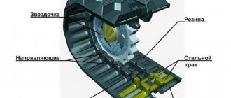
Track tension is controlled by measuring the sag of the track chain. The caterpillar is adjusted correctly if the amount of slack in its free chain, measured in the area between the axles of the support rollers, is from 30 to 50 mm.
To tension the track, it is necessary to add working fluid to the hydraulic mechanism using a lever-plunger syringe. For this:
– remove the extension with the head from the syringe and install the adapter assembled with the sleeve onto the syringe, pump the working fluid so that no air remains;
- unscrew the plug 3
(Fig. 8.24), screw the second adapter into valve
2
. Install the syringe with the sleeve on the adapter and pump the working fluid into the mechanism until the track is tensioned;
– unscrew the adapter from the valve hole 2 and install plug 3. Unscrew the adapter with the sleeve from the syringe, screw on the extension with the head.
To loosen the track tension, you need to unscrew the plug. 5
no more than 3–4 turns, and excess lubricant will be squeezed out through the hole in the plug due to excess pressure in the hydraulic cylinder.
Rice. 8.24. Cart:
1
– adjusting gaskets;
2
– valve;
3
– plug;
4
– sealing ring;
5
– plug;
6
– oiler;
7
– clamp;
8, 9
– liner;
10
– single-sided roller;
11
– double-sided roller;
12
– support roller;
13
– bracket;
14
– shield;
15
– release mechanism;
16
– tension mechanism;
17
– spacer;
18
– tension wheel;
19
– cover;
20
– pointer;
21
– trolley frame;
22
– shock absorber;
23
– stop;
A
– gap 2+1.5 mm;
L
– gap not less than 4 mm
It is not recommended to tension the track until the idler wheel axle extends beyond the index point of the bogie frame.
When loosening the track, it is PROHIBITED to completely unscrew the plug, as this may cause the plug thread to break and lubricant to be released under high pressure.
.
It is PROHIBITED to release lubricant from the hydraulic cylinder by unscrewing the valve.
After the lubricant is completely released due to excess pressure, the plug can, if necessary, be unscrewed to inspect the gasket or clean the hole.
If, when turning the plug 3-4 turns, lubricant does not come out of the tension mechanism cylinder, screw the plug all the way and perform the following operations:
– remove the shield covering the springs of the release mechanism;
– place a metal rod with a diameter of 50 to 60 mm and a length of 1 m into the cavity of the drive wheel sprocket. Slowly moving the bulldozer in reverse, compress the springs of the release mechanism;
When performing this operation, the bulldozer operator and his assistant must be extremely attentive and careful.
– into the gap formed between the front bracket of the trolley frame and the flange of the springs of the release mechanism, insert a steel bracket or two strips of thickness equal to the gap. Move the bulldozer forward to its original position and remove the rod from the sprocket.
In this case, the tension of the track will weaken and there will be no excess pressure in the cylinder of the tension mechanism (to ensure that, move the tension wheel forward with a crowbar). In this position the plug 5
(Fig. 8.24) unscrew completely, inspect and clean the channels in the plug and in the flange of the tension mechanism, then replace the plug and perform the above operations in reverse order.
Track adjustment.
With proper mutual installation of the side clutch housing and track bogies, the drive wheel should be in the same plane with the idler wheel and the center line of the rollers.
In this case, it is necessary to ensure a gap L
between the ends of the drive wheel crown and the inner ends of the track rollers, which must be at least 4 mm (Fig. 8.24).
the gap L
using spacers installed in the end bearing of the final drive.
The crawler carts are equipped with tension wheels with position adjustment along the bulldozer track in the transverse direction.
When operating a bulldozer, in case of one-sided wear of the roller flanges or the rim of the tension wheel, adjust the position of the wheel along the track, moving it along the frame outward or inward of the bulldozer. The movement is carried out by removing the adjusting shims from under the cover on one side and transferring them under the cover on the other side. 1
.
Gap A
must be maintained.

