DIY electronic ignition gas 52
Hello, Dear Friends! This topic primarily concerns those Guys who cannot look without tears at the old ignition systems of carburetor engines, with distributors and contacts!
This topic is in no way related to restoration, only modernization and modern equipment! It is necessary to install a new and more progressive one instead of the outdated ignition system!
So, the hood is open, friends! Please offer your versions, we will all install the best and currently suitable ignition system on this engine and test it in operation.
We dismantle the remnants of the past, to be continued.
__________________ Manage your DREAM and don’t deny yourself anything!
To view links or images in signatures, you must have at least 0 message(s). You currently have 0 message(s).
This is of course all very interesting, but there is one BUT. This is again the Stone Age, transistors and switches, distributors and high-voltage wires are relics of the past and that’s all, I want to cry “hot” tears! It’s clear that it works, but we live now, and now it’s 2011 and “DIGIT” rules the roost, which means that the GAZ-52 engine needed microprocessor ignition just yesterday, in short, it needs “brains” straighten or season, understand it as you want, let’s “digitize this indestructible motor”, it’s high time and necessary.
Where to begin?! Yes, let's start with the crankshaft, everything begins with it, everything depends on it, or rather we need a pulley, a new pulley with teeth and with one tooth missing to start the count for the sensor, which we will then install on the timing gear cover!
Let's remove the pulley and try to find a new one to work with the microprocessor!
__________________ Manage your DREAM and don’t deny yourself anything!
To view links or images in signatures, you must have at least 0 message(s). You currently have 0 message(s).
Thank you very much, this is closer to the topic. This means that before you start selecting a microprocessor for the ignition system, you must first select suitable pulleys for the crankshaft, water pump and generator for a wide belt, and it’s best to make them yourself from aluminum! This is what we will do in the near future to begin with. Once again, Thank you very much.
Today is Saturday, which means that on Saturday there is a flea market at the Fortuna car market in Rostov-on-Don, we take with us the pulley, flange and nut removed from the GAZ-52 engine and try to find the necessary analogue, only with teeth and for a wide belt!
Possible wiring faults
If electrical equipment stops working, you need to check the wiring.
It is characterized by several malfunctions:
- A broken wire is often a consequence of its installation in an unreliable place. When laying wires, you need to take into account that they should not come into contact with moving parts.
- Leakage current. Usually such a malfunction occurs due to a breakdown in the wire. In order to prevent such a problem, all wiring must be reliably insulated.
- Poor contact. As a rule, this failure is associated either with oxidation of the contact or with disconnection of the cable from the equipment due to poor fixation or vibrations.
Read also: Which cover is better for an ironing board
Ignition system GAZ-52
The ignition system is the main part of the car’s electrical equipment and is responsible for the timely appearance of a spark in the engine cylinders. The GAZ-52 is factory equipped with a battery contact electric ignition system and has a device that is standard for most cars. To ensure correct operation of the vehicle's power unit, it is necessary to carry out periodic maintenance of this system and perform routine replacements of its main elements.
In the gaming and souvenir industry
| This section is missing references to information sources. Information must be verifiable, otherwise it may be questioned and deleted. You may edit this article to include links to authoritative sources. This mark is set November 5, 2013 . |
- Scale models of GAZ-52 and GAZ-53 trucks on a scale of 1:43 are produced in small series by the Ukrainian workshops “Vector-models” and “Kherson-model”.
- In May 2013, a beige model from DIP Models went on sale.
Main components of the system
To perform its main function, that is, the appearance of a spark that ignites the fuel mixture in the engine cylinder, the GAZ-52 ignition system contains the following main elements:
Diagram of the GAZ-52 ignition system
- Battery. It is the main element for supplying electricity to the primary electric ignition network, which requires low frequency currents to power it. When the engine is running, energy is provided in parallel by the vehicle's generator.
- Ignition coil type B-115V-01. It has a pulse transformer device, the task of which is to convert low-voltage currents into high-voltage pulses, which are responsible for creating a spark on the spark plug. It consists of two voltage circuits: primary (low) and secondary (high), separated from each other by insulating gaskets.
- Distributor, or distributor GAZ-52. It ensures a uniform supply of impulses from the coil to the spark plugs, and is also responsible for the ignition moment or the time interval between impulses, depending on the number of revolutions and engine load. This module uses a cam or contact distribution system.
- Candles (with thread length 12 mm). They are directly installed in the engine and are responsible for supplying a spark to the fuel in the combustion chamber. Structurally, they have a gap that is broken through by a high voltage pulse and ensures the mixture is ignited. The GAZ-52 uses spark plugs marked A10N or similar; The recommended replacement cycle is 8–13 thousand kilometers.
Device and characteristics
The Gorky Automobile Plant produced several modifications of the car, differing in the length of the wheelbase and attachments. All cars are based on a frame, the axles are equipped with spring dependent suspension, and hydraulic shock absorbers are used at the front. Additional sheets are used at the rear, which work with increasing load weight. The frame of the vehicles, which have a base of 3700 mm, was borrowed from GAZ-53 trucks.
Load capacity and other performance characteristics do not depend on the length of the base. All vehicles are designed to carry 2500 kg of cargo and reach a speed of 70 km/h. The cars use a 4-speed transmission equipped with a synchronizer for 3rd and 4th speeds. Gear shifting is performed using a lever located on the cabin floor.
The box allows the installation of a power take-off gearbox designed to drive additional equipment. An example would be a pump installed on a fuel tanker. To complete the dump truck chassis, a box with spur gears without a synchronizer was used.
There were 2 types of rear axles on trucks. Some machines used a detachable bridge with a conical main pair. Less common was a design with a one-piece crankcase, equipped with a hypoid gear. A design feature of the cars was 6-window wheels; the wheel size was 7.50*20 (or 220-508). The brake system is drum type, equipped with a hydraulic drive with a vacuum booster.
The side body is made of wood, the sides are folding. The driver and 2 passengers are located in a closed metal cabin equipped with a panoramic windshield. The trucks used 2 types of cladding - with trapezoidal and rectangular design of the radiator ventilation slots.
Dimensions of GAZ-52 and technical characteristics:
- base - 3300 and 3700 mm;
- length - 5708 and 6395 mm;
- ground clearance - 347 mm;
- loading height - 1210 and 1280 mm;
- total weight - 5170 and 5465 kg;
- Fuel tank capacity - 90 l.
Engine
Production cars used an inline 6-cylinder engine with a lower valve mechanism. With a working volume of 3485 cm³, the unit develops a power of 75 hp. at 2600 rpm. The design of the cylinder head provides a compression ratio of 6.7, which provides for the use of A-76 gasoline as fuel. At the same time, the standard fuel consumption per 100 km is 20 liters. On GAZ-52-01 vehicles with a long wheelbase and a van-type superstructure, fuel costs increased by 2-3 liters.
The engine design includes a 4-bearing crankshaft; a gear guitar is used to drive the gas camshaft. Mineral motor oil is used for lubrication; the sump capacity is 7 liters. The plant serially produced engine modifications designed for operation on compressed or liquefied gas. The use of compressed gas led to a drop in power to 65 hp; with liquefied gas, the engine develops 73 hp.
Due to the cessation of production of fuel with an octane rating of 76-80, owners are converting the engine to 92 gasoline. To do this, the head is ground, which allows the compression ratio to be increased. Another way to increase compression is to install pistons from a UZAM-412 passenger engine. It is also necessary to increase the ignition timing, the value is selected experimentally. The problem is the durability of the exhaust valves, since fuel burns out on them, increasing the temperature. On such an engine, sudden acceleration and cranking to high speeds should be avoided.
Electrical equipment
The wiring diagram used on the truck consists of 1 wire, the frame and accessories are used as the negative pole. The operating voltage is 12 V, the sources of electric current are a generator and a lead battery with a capacity of 75A/h. A generator with a built-in rectifier is installed on the engine, equipped with a V-belt drive from the crankshaft. To repair and maintain circuits, a color wiring diagram is used, which was changed during the modernization of the truck.
Signs of ignition malfunction
As in any other car, in the GAZ-52 a faulty electric ignition system primarily affects the operation of the power unit. In this case, the following “symptoms” may be observed:
- Difficulty starting the engine.
- Lack of stable idle speed.
- Loss of power due to increased fuel consumption.
- Interruptions in engine operation when driving.
- Engine does not start.
As a rule, with a working fuel supply system, such signs indicate that the system is not functioning properly and requires adjustment.
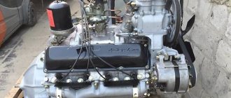
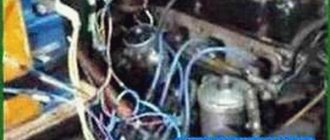
This is what the GAZ-52 engine looks like
To watch online, click on the video ⤵
Contactless ignition gas 52. Disassembling the distributorRead more
Installation of ignition from contact to contactless (electronic) GAZ-53, GAZ-3307, GAZ-66, ZIL-130More
HOMEMADE TRANSMBLER FOR CONTACTLESS IGNITION FOR GAS 52More details
three-circuit ignition for gas engine 51, 52More details
Kara on the gas. Gas 52 contactless ignition. Read more
Examination. Contactless distributor gas 52, 51, 63, Lviv loaderMore details
Switches 131.3734 and 13.3734 UAZ, GAZ, PAZ. differencesRead more
New life of the Lviv loader. Installation of electronic contactless ignition GAZ 52, GAZ 51More details
UAZ AND IGNITIONMore details
GAS -51 ENGINE. Problems of modernization. Read more
Ignition system contact and without 1 partRead more
ELECTRONIC IGNITION AND OPERATING PRINCIPLE 05 56 094More details
The simplest ignition, starting, charging system. Installation. (Ch5) Read more
Correct connection of the ignition coil and more.Read more
Review of the Retro Beast GAZ 52-01.More details
ICE theory: Three-circuit ignition system on the GAZ-51Read more
Contactless ignition system for GAZ-53More details
Attention! Ignition switch, ignition coilRead more
Source
Diagnostics and troubleshooting of ignition faults of GAZ-52
In order to identify a specific faulty link in the overall system, it is necessary to perform a certain sequence of actions.
Pre-check
You must start with this list of actions if the engine starts, but is unstable in all modes.
Carry out a visual inspection of high-voltage wires, including checking:
- Insulation integrity; at the slightest violation of the insulating layer, it is necessary to replace it.
- Contact states; clean and remove oxides if necessary.
- Connection tightness with spark plug tips and distributor cap; tighten the wire sockets to improve contact.
Inspect the condition of the spark plugs by performing the following actions:
- If there is carbon deposits, it must be removed using fine-grained sandpaper.
- Check the distance between the electrodes, which should be within 0.8–0.9 mm; in case of deviation, it is necessary to adjust by bending the side contact.
- Check the performance of each of the spark plugs sequentially, including:
- With the engine not running, disconnect the wire from the spark plug.
- Start the engine and evaluate its operation.
- If its performance has not deteriorated, then the spark plug is serviceable, otherwise replace the spark plug.
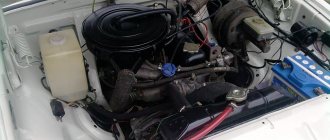
Preliminary inspection of the GAZ-52 engine
Assess the contacts of the breaker and slider in the distributor, clean if necessary or replace. Additionally you need to do the following:
- Check the parallelism of the breaker contacts and their tight fit to each other.
- Measure the gap between the contacts and adjust if necessary using this algorithm:
- Clean parts from oil and carbon deposits.
- Place the cam against the contact with maximum clearance.
- With the locking nut of the locking plate loosened, set the gap with the adjusting screw within 0.35–0.45 mm.
- Secure with a lock nut.
How to determine the malfunction?
You can determine the malfunction in the electrical wiring either yourself or with the help of a specialist.
There are only two vehicle states in which the equipment may not work:
- The car won't start or drive. In this case, first of all, you should diagnose the battery, starter, ignition switch, distributor, spark plugs. As a rule, the problem lies precisely in the spark plugs or battery; the problem of high-voltage wires is diagnosed much less often.
- The car starts and drives, but the electrical equipment does not work. If we are talking about optical lamps, then perhaps the problem lies in their burnout or failure of the fuse. If a group of devices refuses to work, for example, turn signals and wipers, then it makes sense to check the functionality of the steering switch. If there are problems with the operation of certain devices, but you are sure that the devices themselves and the fuses responsible for their operation are working, then you need to check the wiring. You will need a multimeter or an electrician to do this.
Diagnostics of battery charge with a multimeter
Ignition installation
The ignition installation must be done with great precision, since even with small errors in the installation, fuel consumption increases sharply and engine power decreases.
In addition, there may be cases of breakdown of cylinder head gaskets, burnout of valves, piston heads, jumpers between adjacent compression chambers in the head, etc. phenomena caused by detonation.
The current interruption by the breaker when installing the ignition should occur on GAZ-51 and ZIM-12 engines at the moment corresponding to the top dead center of the compression stroke in the first cylinder, and on M-20 and GAZ-69 engines, not reaching it by 4°. Accordingly, the rotor must be located opposite the cover electrode connected to the wire going to the spark plug of the first cylinder.
If the oil pump and distributor were removed from the engine (for example, during repair or replacement), then they must be correctly installed in their places to install the ignition.
The procedure for installing an oil pump on the engine is described in the “Lubricating System” section of Chapter I when describing the oil pump.
To install the ignition distributor on the engine, you must:
a) set the engine crankshaft to the position of the top dead center of the compression stroke in the first cylinder;
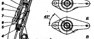
b) make sure using the mandrel shown in Fig. 160 a that the oil pump is installed correctly. In this case, the pointer of the mandrel, inserted all the way into the hole for the distributor, should be directed vertically upward, as shown in Fig. 160 b, with a deviation from the indicated position of no more than 5° in any direction;
c) install the protrusion on the distributor shaft of the GAZ-51 and ZIM-12 engines so that it is perpendicular to the plane passing through the axis of the distributor shaft and the holes in the plate for attaching the distributor to the block (Fig. 161 a), and on the distributor of M- 20 and GAZ-69 so that it is in a plane parallel to the plane passing through the axis of the distributor roller and the center of the articulated connection of the octane-corrector rod with the lower plate, and would be shifted towards this rod (Fig. 161 b);
In this case, the current-distributing contact of the distributor rotor must be facing towards the cover electrode connected to the wire going to the spark plug of the first cylinder;
d) carefully insert the distributor into the block so that the hole or the middle of the arc slot in the lower mounting plate of the octane corrector, intended for the screw securing the distributor to the block, is located opposite the corresponding threaded hole in the boss of the block.
When installing the distributor, you must ensure that its shank does not touch the walls of the hole in the block and does not rotate into its body. In this case, the protrusion on the distributor shank should fit into the slot on the oil pump shaft;
e) insert and tighten the screw securing the lower mounting plate of the distributor to the block boss. To install the ignition:
a) adjust the gap between the contacts of the distributor breaker, as indicated above;
b) set the crankshaft to the position corresponding to the top dead center of the compression stroke in the first cylinder (on GAZ-51 and ZIM12 engines) or not reaching it by 4° (on M-20 and GAZ-69 engines);
c) disconnect the vacuum regulator tube; d) remove the distributor cap and make sure that the rotor is against the electrode in the cap connected to the wire going to the spark plug of the first cylinder;
e) having first made sure that the engine compartment lamp is in working order (by turning it on and off), remove the end of its wire from the coupling and connect it using an additional piece of wire to the low voltage terminal of the induction coil, to which the distributor breaker wire is connected, and turn the lamp lever to the on position position;
f) set the octane corrector scale pointer against the “O” division. This is done on distributors equipped with a device for smoothly adjusting the octane corrector by rotating two nuts intended for this purpose, which, after setting the arrow to “O”, should be carefully locked, tightened tightly by hand. For distributors of earlier production, without the specified device, the pointer is set to “O” by turning the distributor body directly by hand, with preliminary loosening of the screw securing the installation clamp to the octane corrector plate, which, after setting the pointer to “O”, should be tightened again to fix the pointer and the distributor housing in this position;
g) turn on the ignition and, without disturbing the zero setting of the octane corrector, carefully turn the distributor housing clockwise so that the breaker contacts are closed, then slowly turn the housing counterclockwise until the light flashes, which will correspond to the moment the breaker contacts begin to open. You need to stop the rotation of the distributor exactly at the moment the light flashes. If this fails, the operation must be repeated by turning the distributor body to its original position.
When setting the moment when the contacts begin to open, lightly press the distributor rotor with your finger, trying to turn it counterclockwise (that is, against the direction of rotation) in order to select the lateral clearance in the distributor drive;
h) while holding the distributor body from rotating, fix its position in one way or another (depending on the design of the octane corrector);
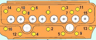
i) attach the vacuum regulator tube, put the distributor cap and the central wire in place. Check the correct connection of the wires from the spark plugs to the distributor, starting from the first cylinder. They, counting clockwise, must be connected in the following order: 1—5—3—6—2—4 (on GAZ-51 and ZIM-12 engines) and 1—2—4—3 (on M-20 engines and GAZ-69);
j) put the ignition installation hatch cover in its place on the clutch housing and connect the wire of the engine compartment lamp to the coupling (in its original place).
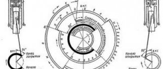
The final check and fine-tuning of the ignition installation by listening to the engine while the car is moving is carried out using an octane corrector, the movement of the arrow of which, and with it the distributor housing, by one scale division corresponds to a change in the clamp setting -
rotation by 2 degrees, counting along the crankshaft.
When turning the distributor body clockwise, the ignition setting will be delayed; when turning counterclockwise - earlier.
Checking engine operation during final ignition adjustment is carried out as follows:
a) warm up the engine to a temperature of 70-80°C;
b) moving in direct gear on a flat road at the speed indicated in the table. 38, give the car acceleration by sharply pressing the accelerator pedal. If a slight and short-term detonation is observed (mistaken by drivers for the “knock” of fingers), the ignition timing has been set correctly. In the event of severe detonation, the distributor body should be turned one division of the octane-corrector scale clockwise, and in the complete absence of detonation, one division counterclockwise;
Suspension
The suspension of this car was leaf spring, and it was also modernized. The designers changed the method of attaching the springs. Now it was carried out using rubber pads. This made it possible to free the main sheets from the force that acts on them during the process of twisting the springs. Thus, the characteristics of the GAZ-52 have been simplified, and repairs and maintenance have become more “dirty”.
To increase the truck's maneuverability in adverse road conditions, engineers developed and implemented new rear axles with cam differentials. Thus, the car became much more confident in passing difficult sections of roads.