Which side should I put the clutch disc on MTZ 80?
The disk is inserted into the flywheel with the side on which the hub rivets are flat and have a slot or a chisel, with the convex caps outward (they will touch the flywheel bolts if placed incorrectly).
Interesting materials:
Why are Leos considered kings? Why are magnetic lines closed? Why is Makar Chudra a romantic work? Why is McGregor a notary? Why does Margarita forgive Frida? Why does my Janome machine skip stitches? Why doesn't butter spread on bread? Why is swearing considered swearing? Why is Genshin Impact loading slowly? Why are raspberries small?
How to repair a KAMAZ clutch
Repair of the KAMAZ clutch cylinder should be carried out after the problem with the tightness of the PGU and its pumping has been eliminated.
After bleeding is completed, press the clutch pedal, turn the air bleed valve all the way, and then remove the hose from the head of this valve and put on the cap for protection.
The fluid level inside the master cylinder is then set to the correct level. Repair of the KAMAZ clutch master cylinder and replacement of the KAMAZ clutch master cylinder imply this operation as mandatory. The brake fluid released from the hydraulic system during bleeding can be used again after it has settled and further filtered. The quality of pumping is determined by the stroke of the pneumatic hydraulic booster pusher.
It is necessary to check the presence of condensation inside the power cylinder of the pneumatic hydraulic booster. To drain the condensate, you need to unscrew the plug of the aluminum housing of the pneumatic power steering. To drain completely, lightly press the clutch (pedal).
At least once every 3 years, the hydraulic system in the clutch drive should be flushed with methanol or brake fluid, the master cylinder and pneumatic hydraulic booster should be disassembled, and fresh brake fluid should be added.
Clutches for Kamaz
Clutch
KamAZ and MAZ are cars that have gained particular popularity due to their exceptional reliability. They are used in literally all spheres of life - cargo transportation, construction, agriculture, and even off-road racing is often held on KamAZ trucks. Time-tested quality will not let you down if you operate the vehicle correctly and service the components and assemblies on time. Experts advise paying special attention to such procedures as adjusting the MAZ and KamAZ clutch. In case of any malfunctions, the KamAZ clutch basket is changed in a very short time. Let's figure out why the clutch of MAZ and KamAZ requires special attention.
Design features
Kamaz clutch
As a rule, KamAZ vehicles are equipped with a dry double-disc (in rare cases single-disc) friction-type clutch. This device is common in almost all heavy, high-power machines. It requires constant maintenance due to the fact that during operation, due to the great power of the vehicles, these clutches experience enormous loads. So, in what cases does it become necessary to adjust the clutch of MAZ and KamAZ:
- The device clearly slips at high speeds.
- The pedal free play does not meet the standard values.
- A mechanical noise occurs when changing gears.
Clutch adjustment
If you notice even one of the listed signs, it means that the KamAZ clutch basket requires adjustment. If this is not done in time, problems may spread to the gearbox and other transmission parts. In general, proper adjustment of the Kamaz clutch can be divided into 3 main stages:
- Adjusting the pedal free play. The standard value for free play is in the range of 6–12 mm. It should be measured from the middle part of the plate at the moment when the pedal is lowered until you feel resistance when pressing. The free play is adjusted with an eccentric finger - it connects the pusher eye with the pedal lever. The pin should be rotated until the gap between the upper stop and the piston pusher reaches 6–12 mm. Once the desired value is reached, tighten and cotter the castle nut. Afterwards, be sure to measure the full pedal stroke, it should be 185–195 mm.
- Adjusting the clutch free play. The free play should be 3.2–4 mm. Measuring it is not difficult at all. We move the fork shaft lever away from the adjusting spherical nut of the pusher. Don't forget to remove the spring and note that the lever should move a maximum of 4-5mm. If discrepancies with the standards are noticed, the situation can be corrected using a spherical nut. As soon as the lever stroke reaches 4–5 mm, the free stroke of the clutch will automatically take on the desired value.
- Adjusting the full stroke of the booster pusher. It is measured very simply. Depress the clutch until it hits the floor. If the pushrod travel distance is less than 25 mm, first check the pedal free play and the fluid in the master cylinder. If everything is in order there, release the air from the hydraulic system and then everything will return to normal values.
Clutch
Section 3. TRANSMISSION
Clutch
The clutch is designed to ensure smooth starting of the Kamaz 4308 vehicle and disconnect the engine from the transmission when changing gears. Consists of a clutch mechanism and a clutch drive.
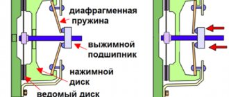
The clutch is a single-disc, diaphragm, pull-type model MFZ-350 from ZF Sachs (Germany) (Fig. 3-1).
A feature of the single-disc diaphragm clutch mechanism of the pull-out type mod. MFZ-430 is that to release the clutch, a drive is used without a gap between the clutch release clutch and the diaphragm.
Rice. 3-1. Clutch mechanism model MFZ - 350: 1 - drive shaft; 2 - flywheel; 3 — driven disk; 4 — pressure disk; 5 - thrust ring; 6 - diaphragm; 7 — clutch casing; 8 — clutch release; 9 — clutch release fork; 10 — clutch release fork shaft; 11 — pneumatic hydraulic booster; 12 - M10 bolt.
Pressure plate 4 is fastened with rivets to clutch housing 7 through four sets of connecting plates. Torque from the engine through flywheel 2 is transmitted to the clutch housing and plates to the clutch pressure plate and then to the friction surface of the driven disk 3, the hub of which is installed on the splines of the drive (primary) shaft 1 of the gearbox. The stamped housing is installed on the flywheel using 8 bolts. Between the casing and the pressure disk there is a diaphragm spring 6 of the exhaust type, under the action of which the driven disk is clamped between the pressure disk and the flywheel.
Lubrication of the release clutch bearing and the clutch release fork shaft is not provided during operation.
The clutch release device consists of 16 diaphragm blades and clutch release 8, installed directly on the diaphragm blades themselves using a thrust ring.
Clutch Specifications
| Clutch model | MFZ 350 |
| Transmitted torque, Nm (kgf.m) | 620 (62) |
| Number of rubbing surfaces | 2 |
| Diameter of friction linings, mm: | |
| outer | 350 |
| interior | 200 |
| Thickness, mm: | — |
| driven disk with linings | 10 |
| overlays | 3,6 |
| Compression spring: | |
| type | central, diaphragm |
| quantity | 1 |
| Diaphragm force during adhesion, kN (kgf): | |
| included | 11,6 (1160) |
| Parameters of pressure diaphragm spring: | |
| thickness, mm | 4,3 |
| diameter, mm: | |
| outer | 393 |
| bearing contact | 120 |
| number of petals | 24 |
| Force on the release clutch, N (kgf) | 2500 (250) |
| Damper type | spring-friction |
| Maximum damper rotation angle, degrees. | 1,7 |
| Driven disc hub splines: | |
| type | straight-sided |
| quantity | 10 |
| diameter, mm: | |
| outer | 50,8 |
| interior | 44 |
| groove width | 7,8 |
| Stroke of the release clutch, mm: | |
| free | No |
| worker | 11-13 |
| Release bearing type: | ball, single row, closed |
| Clutch pedal: | |
| stroke, mm; | 145-150 |
| maximum force, N (kgf); | 150 (15) |
| servo type | spring, pedal |
| Weight, kg: | |
| clutch assembly (without flywheel and drive mechanism), kg | 21 |
| driven disk | 4,2 |
| Clutch control drive | hydraulic with pneumatic booster, has a tracking device |
The clutch control drive is hydraulic and equipped with a pneumatic booster.
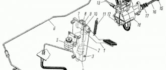
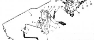
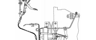
The hydraulic clutch release drive is designed for remote control of the clutch. The hydraulic drive (Fig. 3-2) consists of a clutch pedal 1, a master cylinder 2, a pneumatic-hydraulic booster 12, a system of pipelines and hoses.
The clutch pedal is located on the left in front of the driver and is installed on bracket 4, mounted on the front panel of the cab. The pedal axis is installed in two supports welded to the bracket and secured in one of them with a cotter pin. The pedal rotates on an axis on a bushing made of anti-friction material. The axle is lubricated with grease 158, which is added during assembly. The pedal travel is determined by two stops screwed to the bracket. The limiter located in the middle part of the bracket limits the pedal travel when it moves down (when the clutch is disengaged), and the limiter located in the upper part of the bracket when it moves up (when the pedal is released and the clutch is engaged). The pedal is constantly pressed against the upper travel stop by a spring.
Rice. 3-2. Clutch drive:
1 - pedal; 2 - main cylinder; 3 - lower stop; 4 — bracket; 5 - compensation tank; 7 — lever; 8 — master cylinder piston pusher; 9 — eccentric pin; 10 - upper stop; 11 — release spring; 12 — pneumatic booster; 13 — liquid supply tube; 14 — air supply tube.
The master cylinder piston pusher lever is welded to the pedal hub. An eccentric pin is installed in the lever eye, designed to connect to the pusher eye and ensure adjustment of the gap between the pusher and the master cylinder piston when the clutch pedal is released.
The hydraulic master cylinder is mounted on the clutch pedal bracket and consists of the following main parts: pusher, piston, master cylinder body, cylinder plug and spring.
The main cylinder body has two cavities separated by a partition. The upper cavity is intended for filling the hydraulic drive with working fluid through an opening covered with a protective cover, and for storing the required supply of working fluid. With a properly filled and pumped system, the liquid level in the cavity should be 3/4 of the working volume.
The lower cavity serves as the working cavity of the master cylinder, in which a piston with a cuff and a spring is installed. The working cavity is closed on the drive side with a plug.
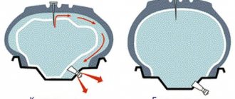
When the clutch pedal is lowered, pusher 2 (Fig. 3-4), connected through eccentric pin 3 (Fig. 3-3) to the pusher lever, is in the upper position. The piston is pressed against the housing partition under the action of a spring. There is a gap between the pusher and the piston; the cavities communicate with each other through a hole in the piston.
When you press the clutch pedal, pusher 2 selects a gap, closes the hole in the piston, preventing fluid from flowing from the upper cavity to the lower, and moves the piston, compressing the spring. The piston, which has a larger area than the bore cross-section of the plug, moves and creates pressure, which is transmitted through hoses and pipelines to the inlet of the pneumatic-hydraulic booster.
When the clutch pedal is released, the piston, under the influence of pressure in the hydraulic system, and the springs return to their original position. Pusher 2, moving together with the clutch pedal, breaks away from the piston and communicates the cavities with each other.
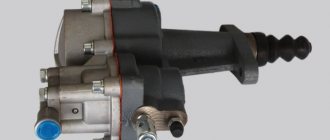
The pneumohydraulic clutch control drive amplifier serves to reduce the force on the clutch pedal and is bolted to the box housing on the left side.
If the pneumatic system fails or there is no air in the pneumatic system, the piston moves when the clutch 5 is released only under the influence of the working fluid pressure. In this case, the force on the clutch pedal increases significantly.
The design and operating principle of the pneumohydraulic amplifier are given in Appendix 10.
Maintenance
The frequency of maintenance operations is given in the “Service Book”.
During maintenance, the following operations are performed:
— check the tightness of the clutch release hydraulic drive;
— secure the pneumohydraulic clutch drive booster;
— adjust the free play of the piston pusher of the main cylinder of the drive and the free play of the clutch release fork shaft lever;
— bring the fluid level in the compensation tank of the clutch master cylinder to normal;
— lubricate the clutch release bearing;
— check the integrity of the clutch pedal release springs and the clutch fork shaft lever;
— change the fluid in the clutch hydraulic drive system.
Checking the tightness of the clutch release drive involves determining the locations of air leaks (check by ear) and fluid (check visually).
Check the action of the clutch pedal release spring as follows: if in the free state the pedal is in its uppermost position, then the pedal release spring is in good condition.
To check the fluid level during operation, you need to open the filler cap of the tank. In this case, the liquid level should be no lower than 15-20 mm from the upper edge of the filler neck.
Adjusting the clutch drive involves checking and adjusting the free play of the clutch pedal.
The free play of the pedal (Fig. 3-3), corresponding to the start of operation of the master cylinder, depends on the size. A (Fig. 3-4) between the piston and the master cylinder pusher; Normal clearance A corresponds to a free play of the clutch pedal of 6-12 mm. The free play of the clutch pedal should be measured in the middle part of the clutch pedal platform. If the pedal free play is outside the specified limits, adjust the clearance between the piston and the master cylinder piston pusher.
Adjust the gap A (Fig. 3-4) between the piston and the master cylinder piston pusher using eccentric pin 3 (Fig. 3-3), which connects the upper eye of the pusher to the pedal lever. Adjust gap A in the position where tension spring 1 (Fig. 3-3) presses the clutch pedal to the upper stop. Rotate the eccentric pin so that the movement of the pedal from the top stop until the pusher touches the piston is 6-12 mm, then tighten and cotter nut 2.
Check the fluid level in the master cylinder reservoir visually using the dipstick from the driver's tool kit. The normal fluid level B in the hydraulic cylinder corresponds to 40 mm on the dipstick, the acceptable level is 10 mm. The total volume of fluid in the clutch hydraulic drive is 280 cm3 (with a reservoir - 380 cm3).
Changing the fluid in the clutch hydraulic system.
To do this, it is necessary to remove air (by pumping) after filling the system with liquid. The liquid level must be no lower than 15-20 mm from the upper edge of the filler neck of the compensation tank (with the tank lid open). Devices, tools and materials required to complete the work: wrench S = 14 mm, rubber hose, measuring ruler.
Rns. 3-3. Free play of the clutch pedal: 1 — pedal release spring; 2 — castle nut; 3 — eccentric finger; 4 - servo spring; 5 - lock nut; 6 - nut.
Rice. 3-4. Gap adjustment: 1 - plug; 2 - pusher; 3 - main cylinder; 4 - piston; 5 - tank.
Repair
After eliminating the hydraulic drive leak, bleed the clutch drive hydraulic system in the following order:
1. Clean the rubber protective cap of the bypass valve from dust and dirt, remove it and place the rubber hose supplied with the Kamaz 4308 vehicle onto the valve head. Lower the free end of the hose into Neva brake fluid poured into a clean glass container;
2. Press the clutch pedal sharply 3-4 times, and then, leaving the clutch pedal depressed, unscrew the bypass valve 1/2-1 turn. Under the influence of pressure, part of the liquid and the air contained in it in the form of bubbles will come out through the hose;
3. After the liquid stops escaping with the clutch pedal pressed, close the bypass valve;
Repeat steps 2 and 3 until the release of air from the hose completely stops. During the bleeding process, it is necessary to add brake fluid to the system, not allowing its level in the compensation cavity of the master cylinder to decrease by more than 2/3 (or 15-20 mm from the upper edge of the compensation tank) from normal in order to avoid atmospheric air entering the system ( in the compensation tank the level is not allowed to decrease by more than 40 mm from the top edge).
After pumping is complete, with the clutch pedal depressed, screw the bypass valve all the way, and only then remove the hose from its head and put on the protective cap. Next, you should set the normal fluid level in the master cylinder or in the compensation tank. The brake fluid that is released from the hydraulic system during bleeding can be used again after settling to completely remove the air contained in it and subsequent filtration. The quality of pumping is determined by the full stroke of the pneumatic booster pusher.
When filling brake fluid, use a strainer to prevent foreign impurities from entering the hydraulic system.
When replacing the pneumatic booster of the hydraulic clutch drive, release air from the pneumatic drive circuit of the brake system through the valve on the air cylinder, remove the release spring of the clutch fork shaft lever, disconnect the pneumatic pipeline of the pneumatic booster, the hydraulic hose and drain the fluid from the hydraulic drive system, unscrew the bolts securing the pneumatic booster and remove the pneumatic booster with the rod .
To install the pneumatic booster, perform the following operations: secure the booster with bolts; connect the hydraulic hose of the pneumatic booster and the pneumatic pipeline. Pour brake fluid into the compensation tank and bleed the hydraulic drive system. Check the tightness of the pipeline connections; leakage of brake fluid from the connections is not allowed. If necessary, eliminate leaks in tightness by tightening or replacing individual connection elements.
Installation procedure for pull-out clutch mod. MFZ-350 for engine.
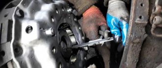
When installing a KAMAZ-141 model gearbox with a CUMMINS V 5.9 180 CIV-0 engine, it is necessary to connect the clutch release fork to the clutch. To do this you need to do the following:
— install the clutch release clutch so that the protrusions on the clutch, on which the fork presses when disengaging the clutch, are located horizontally;
— move the fork towards the clutch and move the gearbox towards the engine;
- turn the clutch so that the fork engages with the clutch to ensure the clutch disengages;
— connect the gearbox to the engine, install the fastening bolts and tighten them to a torque of 5-5.5 kgf.m;
— install pneumohydraulic booster.
Disconnect the gearbox from the engine in the reverse order.
When removing the clutch from the engine after disconnecting the gearbox, unscrew the bolts securing the casing to the flywheel, observing the cross-shaped pattern (Fig. 3-5) for unscrewing the bolts, remove the casing with the pressure plate and the elastic driven clutch disc.
Before installing the clutch on the engine, place 15 g of lubricant 158 into the cavity of the front input shaft bearing located in the crankshaft.
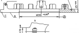
Rice. 3-5. Scheme for tightening (unscrewing) the bolts securing the casing to the flywheel.
Possible malfunctions of the MFZ-350 clutch and its drive, causes and methods for eliminating them
| Cause of malfunction | Remedy |
| The clutch is slipping | |
| Contact of lubricant on the friction surface | Remove the clutch from the engine and wash the friction surfaces or replace the friction linings or driven disc assemblies |
| Wear or destruction of friction linings | Replace friction linings or driven discs assemblies, adjust the clutch drive |
| The clutch "drives" | |
| The clutch drive does not provide the required stroke of the clutch fork shaft lever | Check the serviceability of the clutch drive (possible air entering the hydraulic system, leakage of working fluid, increased free play, etc.) Eliminate malfunctions |
| Warping of the driven disk | Correct or replace the driven disk |
| Excessively increased pedal free play | Adjust pedal free play |
| The fluid level in the master cylinder is low | Restore fluid level |
| Clutch drive jammed | |
| Swelling of the hydraulic clutch seals and loss of their tightness due to the use of non-recommended or contaminated brake fluids. | Replace the seals, flush the hydraulic system with clean Neva brake fluid. |
| Delay in clutch engagement when starting and shifting gears | |
| Solidification of the working fluid (increase in viscosity) in the hydraulic system | Wash and fill the clutch release hydraulic system with Neva brake fluid |
| Pneumatic booster follower piston jammed | Replace the follower piston seal |
| Increased force on the clutch pedal (no force) | |
| Compressed air does not flow due to swelling of the air booster inlet valve | Replace valve |
| Jamming of the follower piston of the pneumatic booster due to swelling of the follower piston of the sealing collar or rubber ring | Replace the cuff or ring of the follower piston |
| Wear or deformation of the amplifier pneumatic piston cuff | Replace cuff |
| Noise in the clutch release mechanism when it is disengaged | |
| Destruction of the clutch release bearing | Replace the bearing or clutch assembly |
| Destruction of the diaphragm spring | Replace the clutch housing with diaphragm assembly |
How to adjust the clutch on a KamAZ
KamAZ is a very reliable vehicle that is used in many areas, mainly for cargo transportation. But, like any other equipment, even it can break down from time to time. The clutch system is subjected to especially heavy loads here. If you do not monitor its condition, it may fail. How to adjust the clutch on a KamAZ to improve the performance of the mechanism?
When to do repair work
Most KamAZ models are characterized by the installation of a double-disc clutch system. In rare cases, only one disk is used, but in modern modifications this option is no longer found. Type – friction, dry. This means that the system provides reliable adhesion to the motor, but at the same time, it is subject to enormous mechanical loads.