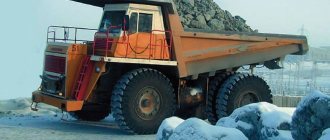
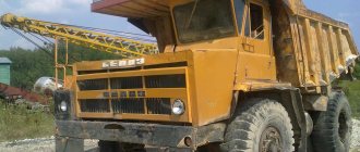
Belaz-7555 is a mining dump truck made in Belarus, produced in seven versions: A, B, D, E, F, I, H. It has a large load capacity and is used for transporting bulk cargo and rock mass. The machine is adapted to work in different conditions and can withstand temperatures from -50 to +50 degrees Celsius.
Depending on the configuration, it can be equipped with air conditioning, a weighing device and other elements. Below we will consider the purpose of such equipment, technical characteristics, features of components, maintenance and repair rules.
Purpose
Belaz-7555 is a vehicle used for transporting crushed rock, as well as bulk materials in off-road conditions. Often used in the construction of industrial/hydraulic facilities, road construction, and tasks in the processing industry.
Important
When choosing a quarry vehicle for work, it is necessary to take into account its type, design features and load capacity, on which the possibility of application in solving certain problems depends.
To increase efficiency and productivity, it is recommended to use such trucks in conjunction with excavators/loaders having buckets with a capacity of 8 to 12.5 cubic meters, reducing loading time.
Engine parameters
Depending on the model of the mining dump truck, the engine and its technical characteristics may vary.
Thus, the power unit of the Yaroslavl Motor Plant YaMZ-845.10 was installed on the Belaz 7555A. This is a V-reverse engine with 12 cylinders, running on diesel fuel and developing power up to 730 horsepower. The engine is turbocharged, liquid cooled and direct fuel injection. The power unit is equipped with sensors that monitor air/oil temperature and pressure, liquid/fuel temperature, crankshaft speed, fuel injection pump position and oil pressure.
- piston stroke - 140x140;
- power - 730 l. With;
- maximum torque - 2744 N*m;
- Fuel consumption at optimal power is 210 g/kWh.
Note that this type of engine was installed only until 1994, after which newer models gained popularity.
Belaz-7555 series B, D and H vehicles are equipped with Cummins KTTA 19-C power units. These are 6-cylinder engines with an in-line arrangement of cylinders and a power of up to 700 hp. With. The main nuance of such units is improved performance and reliability. They are also equipped with twin turbocharging.
- piston stroke - 159x159;
- power - 700 l. With;
- maximum torque - 2731 N*m;
- Fuel consumption at optimal power is 209 g/kWh.
The power unit has a 3-stage lubrication system, exhaust gases released through the body and a liquid cooling system. Starting is carried out using an electric starter.
Belaz-7555 series E and F are equipped with CumminsQSK 19-C. These are 4-stroke diesel units with direct fuel injection and gas turbine supercharging. They have 3-stage air purification and start with an electric starter.
- piston stroke - 159x159;
- power - 750 l. s for E and 700 “horses” for F;
- maximum torque - 2731 N*m;
- Fuel consumption at optimal power is 211 for E and 209 for Fg/kWh.
The Belaz-7555 I has a different type of engine - LiebherrD 9512 A7. This is a 4-stroke diesel engine with a V-shaped cylinder arrangement and gas turbine supercharging. It is also equipped with 3-stage air purification and water-oil oil cooling. Starts using an electric starter.
- piston stroke - 157x157;
- power - 768 hp. With;
- maximum torque—3600 N*m;
- Fuel consumption at optimal power is 210 g/kW*h.
In all cases, the power units of a mining dump truck develop a speed not exceeding 55 km/h.
Specifications
The BelAZ dump truck has the following technical characteristics:
- The carrying capacity of the BelAZ truck is 450 tons.
- The fuel tank capacity is approximately 5600 liters.
- The hydraulic system of the truck holds 538 liters of lubricant and 1800 liters of liquid.
- Dump truck dimensions: length 20.6 m, width 9.750 m, height 8.17 m.
- The weight of the truck without load is 360 tons.
- Two diesel engines with a capacity of 2332 horsepower are installed.
- The torque is 9313 Nm.
- The maximum speed is 67 km/h.
- The truck's suspension is hydropneumatic. The diameter of the shock absorbers is 170 mm.
- 2 fuel tanks with a volume of 2800 l are installed.
- Tire size 59/80R63.
- Wheels 44-63/50.
Specific fuel consumption is 198 g/kWh. For maintenance and repair of the fuel system, there are ladders located on the sides that lead to the tanks. Filter replacements and fuel refueling should be done regularly.
On the landing of the two-flight staircase that leads to the operator’s cabin, there are 8 round glass elements closed with plugs - these are air filters. At the bottom of the cabin there are compact rectangular headlights.
The performance characteristics of the dump truck allow it to be used in various sectors of the national economy when transporting heavy loads over long distances. It is used in construction, manufacturing, etc. This vehicle was created as a quarry-type truck, that is, one of the purposes of the vehicle is to work in quarries, during the development and transportation of minerals, ores of various metals, which have a large weight, volume and oversized dimensions.
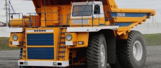
How much does BelAZ weigh?
The largest BelAZ-75710 weighs about 360 tons. The total weight of the loaded vehicle is 900 tons. The wheel of the largest BelAZ weighs 5 tons.
Load capacity
The carrying capacity of the world's largest truck, BelAZ-75710, is 450 tons. The first dump truck of this brand was manufactured in 2013, the customer was. The capacity of the mining vehicle was constantly increasing. In January 2014, the dump truck set a Guinness record when it carried a load weighing 503.5 tons during testing. Due to its high load capacity, the truck is very popular in the construction of large economic facilities and the installation of high-tech structures.
Speed and fuel consumption
The maximum speed of the BelAZ dump truck is 67 km/h. The fuel consumption (fuel consumption) of the BelAZ-75710 is 1300 liters per 100 km.
Transmission
When considering the technical characteristics of the Belaz-7555, it is worth paying special attention to the transmission. The machine is equipped with hydromechanics with a complex 1-stage lockable hydraulic transformer and a “box” with friction clutches for six speeds. The use of such a design guarantees the optimal choice of the appropriate driving mode for the dump truck, simplifies its control and increases operational safety. Structurally, the Belaz-7555 box consists of the following elements:
- hydraulic transformer;
- 4-shaft gearbox with friction clutches;
- microprocessor that protects against overloads;
- emergency control device.
Speed control is based on electrohydraulics, and braking is based on hydrodynamics. The use of a 4-wheel hydraulic transformer reduces loads in the transmission and ensures stable operation of the power unit under different loads.
Dump truck device
To increase stability and increase the smoothness of the ride, BELAZ-7555 is equipped with air-hydraulic suspension with hydraulic shock absorbers paired with a dependent steering mechanism. The BELAZ-7555 device uses a welded frame made of low-alloy steel. It is equipped with additional fastenings for installing equipment. Cast structural elements are used in those places where there is an increased load on the frame (it itself is not solid). To the right of the dumping platform there are three warning lamps that indicate the loading level of the machine.
Chassis
The Belaz-7555 suspension is of a pneumohydraulic type with a structurally more powerful hydraulic shock absorber. The front axle is dependent, equipped with longitudinal levers and transverse rods. This combination guarantees smooth movement, resistance to roll and a long service life of the various components of the dump truck. It is worth noting the high level of comfort for the driver in the cabin. The rear axle of a mining dump truck is a drive axle. It includes:
- 1-speed transmission;
- differential in the form of a cone with 4 satellites;
- cardan.
A pair of open driveshafts combine the hydromechanical transmission, power unit and rear axle.
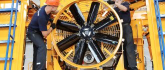
Why electric?
We were working on a machine with a lifting capacity of 90 tons. It is far from the largest (450 tons), but not small either (30 tons). Why are such dump trucks made with an electromechanical transmission and not a hydromechanical one? It turns out that as power increases, it becomes more and more difficult to make the mechanics and hydraulics so that it is reliable, simple and with good efficiency. Layout problems arise.
In addition, as the mass increases, the problem of brakes becomes more acute. With an electric drivetrain, it's very easy to dissipate braking energy into brake resistors and blow off the heat with fans. If you use mechanical brakes on such a mining dump truck, then the brakes will be enough for 500 meters. And since the machines work in quarries with long descents, the problem of braking is very acute in them. Thus, the electrics (as I will briefly call the electromechanical transmission) “at the same time” also solve the problem with the brakes.
The weight of 90 tons is to some extent transitional - some manufacturers still make cars of this weight with a hydraulic transmission, and some, such as BelAZ, already with an electric one. An even larger mass is definitely behind electrics, while smaller machines are still behind mechanics (hydraulics).
Hydraulic system
Control of the Belaz-7555 is simplified thanks to well-thought-out hydraulics, which are common to the body, steering wheel and brakes. This feature makes the system simpler and reduces power losses. The main elements include gear pumps and lifting cylinders.
The latter are made in telescopic form, have two stages and one with double action. Hydraulics provide lifting/lowering of the body in just 11 and 14 seconds, respectively. In this case, the maximum hydraulic pressure is 17 MPa.
Steering and brakes
The design of the steering system complies with ISO 3450 standards in terms of reliability and safety of use. The steering column can be adjusted in angle/height. Thanks to the hydraulic booster, turning the steering wheel does not require heavy loads on the driver. The steering angle of the wheels is 41 degrees, which allows you to turn around within a radius of 9 meters, and the total turning diameter is 20.5 meters. Like the steering system, the brakes also comply with ISO 3450. The dump truck is equipped with several brake systems: main, parking, additional and spare. Let's look at the features of each of them:
- main - single-disc dry in front and multi-disc with cooling in the rear, separate hydraulic drive;
- parking - block with a spring drive mechanism and hydraulic control;
- additional - MMOT on the rear axle with deceleration using a separate pedal;
- spare—use of the main and parking circuits.
This configuration provides reliable braking in different conditions, and the systems themselves protect each other.
Dimensions
| Length | 8,890 mm |
| Width | 5,300 mm (5,700 mm - BELAZ 7555D) |
| Height | 4,560 mm (4,600 mm - BELAZ 7555D) |
| Wheelbase | 4,000 mm |
| Ground clearance | 640 mm |
| Turning radius | 9,000 mm |
| Front track | 3,700 mm |
| Rear track | 2,940 mm |
Cabin
The operating comfort of the Belaz-7555 is also influenced by the cabin, designed for two people, equipped with a pair of seats.
The interior is quite comfortable, and the front glazing provides good visibility. There is nothing superfluous in the interior, but the ergonomics of the workplace are well thought out. The driver's seat is on adjustable air springs. Structurally, the cabin complies with EN 474-1 and 474-6 standards.
They determine the optimal level of noise, vibration, concentration of harmful components and dust. The sound level is no more than 80 dB. Thanks to the large adjustment possibilities, each driver can adjust the seat to suit himself.
Maintenance and repair
To maintain the Belaz-7555 in working condition and increase the service life of its parts, periodic maintenance is necessary. Conventionally, it is divided into several categories: daily (held before departure);
- TO-1 - after 1.5-2 thousand km;
- TO-2 - as soon as the dump truck has traveled 8-10 thousand km;
- TO-3 - after 16-20 thousand km;
- SO (seasonal maintenance) - twice a year;
- TR (current repairs) - between scheduled maintenance, if there is such a need;
- KR (overhaul) - when a component breaks down;
- D (diagnostics) is a mandatory stage before maintenance and repair.
Special attention is paid to preparing the car for the autumn-winter period. This work is carried out in the spring or summer at TO-2. Before carrying out any maintenance, the vehicle must be washed and cleaned. This is done in order to avoid dirt and dust getting into important components of the vehicle. The greatest attention should be paid to daily maintenance. It includes:
- inspection of the machine and its completeness;
- checking the fuel level and draining the sludge;
- monitoring the oil level in the oil pan;
- inspection of oil pipeline connections;
- checking the coolant level and integrity of hoses;
- change in battery voltage (24 V);
- checking headlights and other equipment.
As for TO-1, 2 and 3, they are carried out taking into account the approved plan at specialized services with a mark on the completion of each of the works.
The rear suspension of the BelAZ-540 and BelAZ-540A (Fig. 98) consists of two cylinders, two longitudinal rods, a fork and two buffers.
Rice. 97. Front suspension and steering of cars: 1 - front axle beam; 2 — left steering linkage lever; 3 — suspension cylinder; 4 — lower longitudinal suspension rod; 5 — longitudinal steering rod; 6 — power steering; 7 — steering mechanism; 8 — upper longitudinal rod of the suspension; 9 — car frame; 10 - buffer; 11 — right steering linkage lever; 12 — transverse steering rod; 13 – eye of the transverse suspension rod; 14 — transverse suspension rod; 15 — oiler; 16 — spacer sleeve; 17 — retaining ring; 18 - finger; 19 — spherical bearing; 20 - oil seal; 21 - locking bolt
The fork, together with the rods, absorbs longitudinal and transverse forces. The purpose of the cylinders and buffers is the same as in the front suspension.
The cylinders and rods are connected to the frame brackets and rear axle beam in the same way as in the front suspension. The fork is connected to the frame using articulated bearings, which are sealed with oil seals. Lubricate the bearings through an oiler. Lateral forces are transmitted from the fork to the frame through washers, the thickness of which is selected depending on the gap between the fork eye and the frame bracket. The fork is connected to the rear axle housing by a spherical joint and a king pin. When assembled at the factory, the kingpin is lubricated with VNII NP-242 grease, which ensures the functionality of the kingpin until the vehicle is overhauled. Rubber O-rings prevent water and dirt from entering the joint. The spherical joint is lubricated through an oiler.
The rear suspension of the BelAZ-548A (Fig. 99), in contrast to the rear suspension of the BelAZ-540, has four cylinders.
The suspension of the drive axle of the BelAZ-531 tractor (Fig. 100) is similar in design to the front suspension of BelAZ vehicles, however, the rear ends of the lower longitudinal rods are connected to the frame using conical pins. In this regard, the bearing is closed on one side by an oil seal, and on the other side by a cover.
Rice. 98. Rear suspension of BelAZ-540 and BelAZ-540A cars: 1 - car frame; 2 - fork; 3 — rear axle; 4 — suspension cylinder; 5 — rod; 6 - buffer; 7 — lock bolt; 8, 17 and 24 - thrust washers; 9 — oil seal; 10 - spherical bearing; 11 — retaining ring; 12 and 16 - fingers; 13 — oiler; 14 — king pin cover; 15 — spherical hinge; 18 and 20 - sealing rings; 19 — king pin; 21 - nut; 22 - lock nut; 23 — lock washer; 25 — shims
Rice. 99. Rear suspension of the BelAZ-548A car: 1 - rod; 2 - buffer; 3 — rear axle; 4 — suspension cylinder; 5 — rear suspension fork; 6 - car frame
Rice. 100. Suspension of the BelAE-531 tractor-trailer: 1 - transverse rod; 2 — driving axle; 3 — lower longitudinal rod; 4 - frame; 5 — upper longitudinal rod; 6 — suspension cylinder; 7 - oiler; 8 - cover; 9 — spherical bearing; 10 - retaining ring; 11 — oil seal; 12 - finger
The suspension rods of dump trucks and tractor-trailers are identical in design and differ only in length.
All suspension cylinders (Fig. 101) are also identical in design, but the front cylinders of the BelAZ-540 and BelAZ-540A dump trucks are shorter, and the cylinders of the BelAE-531 tractor truck differ in the length of the pump sleeve 38.
The pneumohydraulic suspension cylinder is a piston-type air spring with a built-in hydraulic shock absorber, consisting of a main cylinder 15 and a backpressure cylinder 14, which is a piston with a hollow rod welded to it.
Compressed gas, nitrogen, is charged into cavity A (Fig. 102) above the piston through the charging valve. Oil is filled into the same cavity (the height of the oil layer above the piston is 20 mm), which serves to prevent gas leakage through the movable connection of the piston with the cylinder, as well as to lubricate the working surfaces.
Rice. 101. Suspension cylinder: 1 - bottom cover; 2, 6, 10, 21, 27, 31, 35, 42, 57 and 65 - rubber sealing rings; 3 - fitting; 4 — cargo; 5, 18 and 32 - traffic jams; 7 — adjusting nut; 8 - spring; 9 - cotter pin wire; 11 — pump valve ball; 12 — cuff body; 13, 19 and 20 - bronze axle boxes; 14 — backpressure cylinder; 15 — main cylinder; 16 — shock absorber valve ball; 17, 26, 29, 33 and 68 - sealing copper gaskets; 22 — spacer sleeve; 23 — pump plunger; 24 and 40 — filling tubes; 25 - nut; 28 — top cover; 30 - charging valve; 34 — clamping bolt; 36 — pump suction tube; 37 - check valve; 38 — pump sleeve; 39 — oil sump housing cover; 41 — protective cover; 43 — lock washer; 44, 50 and 62 - pressure disks; 45, 51 and 61 - pressure springs; 46, 52 and 60 - shims; 47, 53 and 63 - pressure rings; 48, 54 and 58 - rubber spacer rings; 49, 55 and 59 — fluoroplastic sealing cuffs; 56 — bushing; 64 — protective fluoroplastic washer; 66 — oil seal; 67 - cover; 69 — filling fitting
The annular cavity B under the piston and the lower part of cavity B are also filled with oil. Cavities B and C are connected to each other using two tubes 3 and 4. The upper part of cavity B is charged with compressed gas through the charging valve, the pressure of which is transmitted through the liquid to the annular area of the piston in cavity B. Thus, the piston is under gas pressure: from above - main pressure and from below - back pressure.
To prevent oil and gas leaks from the suspension cylinder, the fixed joints are sealed with rubber O-rings, and the moving joints of the piston, rod and pump plunger are sealed with special fluoroplastic cuffs.
PTFE cuffs are installed in the cylinder with tension, which is adjusted by selecting the thickness of the gasket package. The interference formation diagram is shown in Fig. 103. Preference is defined as the difference in diameters Dg and D\, which should be 1.7-2 mm for cuffs 55 and 59 (see Fig. 101) and 1.2-1.4 mm for cuff 49. To maintain tension When the cuffs wear out, springs 45, 51 and 61 serve.
The principle of operation of the suspension cylinder. During the compression stroke, the piston moves upward in the cylinder and compresses the gas in cavity A (see Fig. 102). By increasing the gas pressure above the piston, the compression stroke is elastically limited. In cavity B at this moment, the gas pressure decreases, since the oil flows into the annular cavity B during compression and the volume of cavity B increases.
During the rebound stroke, the piston moves in the opposite direction, the gas pressure in cavity A decreases, and in cavity B increases, due to which the rebound stroke is elastically limited.
Thus, when the car moves, as a result of relative movements of the sprung and unsprung masses, an alternating change in gas pressure occurs in cavities A and B.
Rice. 102. Diagram of shock absorber operation and oil movement in the cavities of the suspension cylinder pump: a - compression stroke; b - rebound stroke
Rice. 103. Scheme of formation of the tension of the sealing fluoroplastic cuff: a - cuff in a free state; b - the cuff is clamped to determine the tension; c — cuff in working position; 1 - spacer ring; 2 - cuff; 3 - pressure ring; 4 - pressure spring; 5 — pressure disk; 6 - bolt; 7 - shims
Rice. 104. Diagram of operation of the suspension cylinder pump
To dampen vibrations that occur when the vehicle moves on uneven roads, the suspension cylinder has a hydraulic
shock absorber, the function of which is performed by tubes. A ball check valve is installed in the tube, which allows the working fluid to flow in only one direction. During compression, the working fluid passes into the annular cavity B through both tubes, and at the moment of rebound - only through a calibrated hole in the tube, which provides the necessary resistance to the flow of the working fluid and helps dampen vibrations.
To maintain a constant oil level in the upper cavity, a plunger pump is installed in the cylinder, which is driven by vehicle vibrations. The pump consists of a plunger connected to the top cover and a sleeve connected to the piston.
The pump starts working only when oil leaks from the upper cavity, when the height of the oil layer above the piston becomes less than 20 mm.
During the rebound, oil from cavity D (see Fig. 102) is sucked through a tube and channel in the plunger into cavity D of the pump sleeve; at the moment of compression, oil from cavity G flows back into the oil sump housing. The pump valve is adjusted in such a way that it closes the channel in the plunger only if the oil level above the piston drops. When, during the compression stroke, the channel in the plunger (Fig. 104) is blocked by the ball and a further compression stroke occurs, the oil enters the gap between the plunger and the sleeve and then through the inclined hole and the check valve into the supra-piston cavity.
The charging valve structure is shown in Fig. 105. The valve's tightness is ensured by a rubber cone. The valve is constantly held closed by a spring. The valve opens by pressing the stem from the side of the cover.
The valve also opens under the influence of pressure supplied from the same side.
The check valve device is similar to the charging valve device.
Suspension Maintenance
After 100 hours, check and, if necessary, tighten all threaded connections of the suspension. Inspect the welds on the rods, forks and suspension brackets. Weld the detected cracks by performing the necessary cutting for the weld seam. Lubricate the suspension joints according to the lubrication chart.
After 500 hours, check whether the pump is filled with oil. To do this, unscrew the plugs on the oil sump housing and on the outer tube 36 of the pump. Insert a funnel with a mesh into the hole on the tube and pour oil until it appears from the hole on the oil sump housing. After this, tighten the plug on the oil sump housing, pour oil into the tube until it is completely filled and make sure that the oil level in the tube does not drop. If necessary, add oil. Tightly screw the plug on the tube, unscrew the plug on the crankcase, allow excess oil to drain and tighten the plug.
If the suspension cylinders malfunction (vehicle roll, increased suspension stiffness, knocking noises in the cylinders), check that they are charged correctly.
Before checking, clear the vehicle platform from any remnants of the transported cargo and place the vehicle on a horizontal platform.
A previously faulty cylinder can be determined by measuring the distance from the mark (conical recess) (Fig. 106) on the bottom cover (on the BelAE-531 tractor from the center hole of the pin) to the lower edge of the oil sump housing.
This size is measured with a special characteristic ruler (Fig. 107) included in the tool kit. There are inscriptions on the ruler indicating. which cylinders and which cylinder cavities are monitored on which scale.
A properly loaded cylinder should have its lip positioned against the cylinder's permissible height zone.
However, the dimensions of all suspension cylinders are interconnected and a change in the height of one (faulty) cylinder causes a change in the height of the remaining cylinders. Therefore, the faulty cylinder should be considered the one whose edge of the oil sump housing is furthest away from the permissible cylinder height zone. In a faulty cylinder, additionally measure the pressure in all cavities using a device (Fig. 108) included in the tool kit. To do this, screw the adapter tightly onto the charging valve, having first removed the cap from it, and screw in the needle until the pressure gauge shows pressure. Do not over-screw the needle to avoid damaging the valve.
Rice. 105. Charging valve: 1 - rubber cone; 2 - bushing; 3 - pin; 4 — body; 5 - spring; 6 — rod; 7 - nut; 8 - cover; 9 - sealing copper gasket
Rice. 106. Determination of the height of the suspension cylinder: 1 - the lower edge of the oil sump housing, against which the reading is made using a ruler; 2 - characteristic line; 3 - mark on the bottom cover of the cylinder for installing the ruler needle
The pressures in the cylinder cavities must be equal to the values of the corresponding ruler scales located opposite the edge of the oil sump housing. The cylinder is considered correctly charged if the pressure gauge and ruler readings differ by no more than 1.5 kg/cm2. Otherwise, the cylinder must be recharged.
After recharging one cylinder, check the heights of the remaining cylinders again and determine which one, if any, is faulty.
Faulty cylinders should be recharged in the following order.
Remove the charging valve covers.
Screw the fitting included in the tool kit onto the lower charging valve until gas begins to exit the valve and release gas from the lower cavity of the cylinder (when recharging the rear suspension cylinder of a BelAZ-548A, all operations must be performed simultaneously with the second rear suspension cylinder installed on the same sides). In this case, the cylinder must be completely expanded (the lower edge of the oil sump housing must be installed against the upper edge of the scale, and for the front cylinders of BelAZ-540 and BelAZ-540A dump trucks - against the upper mark of the scale). If the cylinder is not fully expanded, expand it to the indicated position by recharging the upper cavity with gas.
After decompressing the cylinder, add oil to the lower cavity until a continuous stream appears from the charging valve, which must be open at this time. If, during the decompression of the cylinder, oil flows out of the valve in a continuous stream, then there is no need to add oil to the lower cavity. Oil is added through the fitting, after first removing the cap from it and turning it three or four turns. It is recommended to pump oil into the fitting using some kind of pump that creates a pressure of 1-3 kg/cm2.
Rice. 107. Characteristic ruler:
Rice. 108. Device for measuring pressure in suspension cylinders: 1 - pressure gauge; 2 and 9 — sealing copper gaskets; 3 and 8 — adapters; 4 hose; 5 - nut; 6 - sealing ring; 7 - needle
Rice. 109. Device for charging suspension cylinders with gas: 1 - hose; 2, 5, 12 and 21 - adapters; 3 — compressed gas cylinder; 4 — cylinder valve; 6, 15, 16 and 22 - sealing copper gaskets; 7 - pressure gauge showing the gas pressure in the cylinder; 8 — pressure gauge showing gas pressure behind the reducer; 9 - gearbox; 10 — gear adjustment screw; 11 — gear valve; 13 - valve; 14 — fitting for gas release; 17 — pressure gauge for monitoring the pressure in the suspension cylinder; 18 - nut; 19 — sealing ring; 20 - needle; 23 — suspension cylinder
As soon as the oil begins to come out of the charging valve, screw the fitting in as far as it will go and allow excess oil to drain through the charging valve, then close the valve by removing the fitting from it.
After restoring the required oil level, release gas from the upper cavity of the cylinder. The cylinder must be compressed (the frame must rest with a buffer on the axle housing or front axle beam). If the cylinder does not have a pump, fill the upper cavity of the cylinder with oil. The refueling procedure is the same as for the lower cavity.
Oil is charged through the filling fitting installed instead of the clamping bolt until a dense stream of oil exits through the tube and the upper charging valve. The lower end of the tube is located at a height of 20 mm above the piston, which ensures a normal oil level in the upper cavity.
Charge the lower cavity with gas. The pressure to which it is required to charge is determined using the appropriate scale of the characteristic line.
When completely replacing the oil in the lower cavity or adding more than half of it (about 3 liters of oil in the lower cavity), increase the pressure by 3-4 kg/cm2. Part of the gas will dissolve in fresh oil during the first hours of operation of the cylinder and after that the operating pressure will be established.
When charging the cylinder with gas, use the device included in the tool kit. The device structure is shown in Fig. 109. The procedure for charging the cylinder is as follows: attach the device to a nitrogen cylinder; Screw the adapter of the device tightly onto the charging valve; open the valve on the gas cylinder. The gas pressure in the cylinder is controlled by a pressure gauge; by tightening the needle, open the charging valve, smoothly open the valve and, turning the adjusting screw of the reducer, set the required pressure. Monitor the pressure using a pressure gauge; close the valve; Check the pressure on the pressure gauge again. Excess pressure can be relieved by releasing some of the gas through the valve using a fitting, unscrewing the needle until the charging valve is completely closed and removing the adapter from the valve.
Next, charge the upper cavity of the cylinder with gas. The pressure in the charged cylinder should correspond to the value opposite the lower edge of the oil sump on the Upper Cavity scale.
After recharging the cylinder, fill the pump suction line with oil.
If there are frequent malfunctions in any cylinder (more than once a week), remove it from the car and send it for repair.
Before charging the cylinders, drain the water from the nitrogen cylinder. To drain the water, turn the nitrogen cylinder with the valve down and keep it in this position for an hour. After this, open the valve and drain the water.
Safety instructions for servicing suspension cylinders. Suspension cylinders must be serviced by personnel who are knowledgeable about the design of suspension cylinders and safety regulations.
When servicing suspension cylinders, you must be guided by the following safety rules: do not unscrew the bolts securing the top cylinder cover, charging valves 30 (see Fig. 101) if there is gas in the cavities of the cylinder and the filling fitting without removing the cover from it.
Before removing the plugs, make sure that there is no pressure in the pump suction line by unscrewing the plug one and a half to two turns.
Before removing the cylinder from the vehicle, release gas from the upper and lower cavities and make sure there is no pressure. To release gas, use the special fitting included in the tool kit.
When discharging a cylinder, before removing it from the vehicle, open the valves at least 3 times at intervals of 3-5 minutes to release gas evaporating from the oil.
Before charging gas into the cylinder, make sure that the charging device is in working order. Gas is fed into the cylinder smoothly through the reducer.
When attaching the cylinder charging device to a new cylinder, check the markings on the cylinder. The cylinder must be painted black and labeled Nitrogen. The suspension cylinders must not be charged with other gases. Cylinders charged with oxygen are explosive.
Front axle
The design of the front axle of the BelAZ-548-A is shown in Fig. 110. Beam 28 of the front axle is made of a pipe, onto the ends of which cast casings are pressed. The casings have brackets for fastening cylinders and suspension rods and eyes into which the turning pins are inserted. The pivot pin is connected to the casing using a pin with a nut and a lock washer.
Rice. 110. Front axle: 1 — bead ring; 2 — landing ring; 3 — lock ring; 4 — wheel rim; 5 — “clamp; 6 — wheel hub; 7 - plug; 8 — lock washer; 9 — lock washer; 10 - lock nut; 11 — rotary axle; 12 — outer cover; 13 - nut; 14 — bearings; 15 — brake pad; 16 — brake drum; 17 — rubber gasket; 18 — rim tape; 19 — chamber with valve; 20 — tire; 21 — inner cover: 22 — outer oil seal; 23 - plug; 24 and 31 — bronze bushings; 25 — oiler; 26 - thrust bearing; 27 — installation washer; 28 — front axle beam; 29 — oil seal 30 — adjusting washers; 32 - sealing ring; 33 — washer; 34 - king pin. 35 — spacer sleeve; 36 — brake caliper; 37 - protective disk
In the middle part, for a tight fit into the trunnion hole, the pin has a conical shape. In the holes of the casing, the pin rotates on bronze bushings. To protect the working surfaces of the pivot from contamination, a plug is installed on top, and a felt sealing ring is installed on the bottom.
The pivoting axle absorbs the vertical load from the axle beam through a thrust ball bearing, which rests on a spherical washer.
Vertical movement of the axle relative to the front axle beam is eliminated by shims. The thickness of the gasket set is selected so that the gap between the steering axle and the axle housing does not exceed 0.3 mm.
The bushings and kingpin bearing are lubricated through oil nipples. For better distribution of lubricant, spiral grooves are made in the bushings, and on the king pin there is a longitudinal groove that supplies lubricant to the bearing.
The turning axles have conical holes into which the steering linkage arms are inserted and secured with nuts.
The front wheel hub with the brake drum is mounted on a rotary axle on two tapered roller bearings and secured with a nut, a lock washer, a lock washer 9 and a lock nut. The seal is protected from dust and dirt by an external felt seal.
To stabilize the front wheels when the car is moving, the wheels have a camber of 1°, and the kingpins 34 have a transverse inclination of 6°. To reduce tire wear, the front wheels have a toe-in of 6-8 mm.
The front axles of the BelAZ-540 and BelAZ-540A vehicles are the same. In design they are similar to the front axle of the BelAZ-548A car and differ from it in the sizes of some parts.
The wheel hub bearings are adjusted in the following order.
Raise the front axle of the car and place it on a stand. Remove the cover, bend the lock washer tab, unscrew the lock nut and remove the lock and lock washers. Unscrew nut 13 half a turn and check the wheel for ease of rotation. It should rotate easily, without jamming.
Screw the nut all the way, while turning the wheel, unscrew it until the nut pin aligns with the nearest hole in the lock washer and check the wheel for rotation.
Replace the washers, tighten the lock nut securely and lock it by bending the lock washer tab. Install the cover, placing a cardboard spacer under it.
Finally, the adjustment of the bearings is checked by hand by touch by the heating of the hubs when the car is moving. The hand must be able to easily withstand prolonged contact with the hub. If the hub overheats, unscrew the nut until its pin aligns with the next hole in the lock washer. Adjustment of the toe-in of the front axle wheels is also carried out with the front axle of the car raised and installed on a stand. Before adjusting the wheel toe, check the adjustment of the tie rod joints and the front wheel hub bearings.
Rice. 111. Scheme for adjusting toe and limiting angles of rotation of the front wheels of the car
The adjustment is made as follows.
Rotate the steering wheel to set the front wheels to a position corresponding to the vehicle moving in a straight line.
From the front, at the level of the wheel axle, measure the distance between the side rings of the wheels (dimension A, Fig. 111). Mark with chalk the points at which the measurements were taken. Turn both wheels half a turn and measure the distance between the marked points at the rear at the level of the wheel axle (dimension B). Wheel toe is defined as the difference between dimensions B and A, which should be 6-8 mm.
If the difference (B - A) differs from the specified one, then adjust the wheel toe. To do this, loosen the tie rod end bolts and, by rotating the tie rod pipe with a pipe wrench, set the required difference between dimensions B and A.
The maximum steering angles of the front wheels are adjusted whenever the longitudinal steering rod is removed from the vehicle, as well as when the left steering linkage arm is replaced. Before adjusting the maximum steering angles, adjust the wheel toe, the steering rod joint and set the wheels to a position corresponding to the vehicle moving in a straight line.
The adjustment is made as follows.
Disconnect the steering rod from the power steering. Set the steering wheel to the middle position, keeping in mind that the full travel of the steering wheel from one extreme position to the other is six revolutions. Loosen the tie rod end pinch bolts, adjust its length so that it can be attached to the hydraulic booster without changing the position of the steering wheel and front wheels of the vehicle, and secure the rod to the hydraulic booster. Check rotation angles. They must correspond to the values shown in Fig. 111.
Check the final adjustment according to the turning radius of the vehicle. The smallest turning radius of the vehicle along the track of the outer front wheel should be no more than 8.5 m for the BelAZ-540 and BelAZ-540A vehicles and no more than 10 m for the BelAZ-548A vehicle.
Front axle maintenance
After 100 hours of vehicle operation, lubricate the pivot pins of the axle axles using grease nipples.
After 500 hours, check the wheel alignment, adjust the wheel bearings and lubricate the bearings.
To lubricate the bearings, unscrew the plug, insert the tip of the syringe into the hole and inject grease until it comes out of the gap between the tip and the walls of the hole.