EXCEPTION Increased static load of max. 50 Nm, only allowed for gearboxes in which the power take-off N…/1 or N…/4 is flanged directly to the housing.
PTO torque
Due to the design and type of control, high peak torques may occur. Individual shocks up to 2 times the rated torque are permissible. If exceeded, overload protection is required. A sequence of shock torques or an vibration characteristic exceeding > 1.5xT (effective torque) is not permissible. The specified values apply to a power take-off speed of 1500 min-1.
Installation
Max. The permissible bending angle b of the cardan shaft must not exceed 7°. Please also observe the “ZF Directives for the installation of gearboxes” (1203 765 910).
Actuation of power take-offs
After installation and testing work, the technical personnel must ensure that the unit operates flawlessly again.
CAREFULLY
We point out that before operating the power take-offs, after attaching the propeller shaft bolts, the power take-off flange with the propeller shaft must be manually checked for free movement.
⚠ DANGER
This check must be carried out without starting the engine.
Any warranty liability is excluded for damage resulting from non-observance of these instructions!
Tightening torques
Tightening torques for bolts, screws and nuts, extract from ZF standard 148
For tightening torques of bolts and nuts, see ZFN 148, thread class 4, tightening torque tolerance ± 10%.
This standard applies to bolts according to DIN 835 and DIN 939, and nuts according to DIN 934.
The bolts are tightened using a torque wrench.
The tightening torques are specified in the following manual.
CAUTION Use only original studs and nuts.
Execution options
Execution "b"
with PTO flange Ø 90 mm, 4 holes Ø 8.1 mm (other flange sizes on request)
Version "c"
for direct connection of the pump in accordance with ISO 7653. (Pay attention to the free movement of the pump to the transmission PTO flange and the cardan shaft).
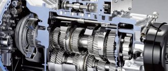
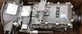
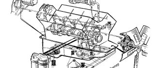
Design and principle of operation
The structure of this box includes the following elements:
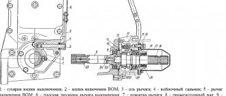
- shift handle;
- drain plug;
- front and back covers;
- rod, driven gear;
- ball retainer element;
- crankcase and gearbox;
- fork;
- driven type axle shaft;
- pump and bearing;
- rear axle intermediate shaft;
- axle, pneumatic cylinder body.
Power transmission begins from the gear unit of the transfer case of the power unit to the PTO drive gear. The mechanisms are in constant engagement with each other; the power take-off is activated by a movable carriage, which begins to engage the teeth.
The PTO is engaged using a gear-type clutch mechanism, which connects both shafts when there is no load on the box. The receiving shaft receives rotation from the intermediate cardan shaft. The second end of the PTO is connected to the secondary shaft of the gearbox. Rotation then passes to the transmission shaft of the high-pressure pump. After this, the rotation is transmitted to the drive axle of the vehicle chassis.
This box is controlled from the cab. The drive can be mechanical, pneumatic or electro-pneumatic.
Preparatory work on the gearbox
Preparatory work on the main gearbox
1 If necessary, drain the transmission oil from the gearbox.
2 Dismantling in numbering sequence.
3 Clean the sealing surface.
NOTE
— The removed parts for installation of N…/10 will no longer be required.
— The outer ring of the intermediate shaft bearing on the drive side is already mounted in advance, and is fixed by a four-fold notch in the housing
Tapered roller bearing
Check before installation!
The same intermediate shaft must be used for all gearbox versions 9 S 1110 TD, 9S 1110 TO and 9S 1310 TO.
Intermediate shaft - 14 teeth (shaft 1304 313 177)
Complete shaft 1304 213 062
Measuring and Installing Tapered Roller Bearing
During measurement and installation, both tapered roller bearings must have no play and no axial preload. The free, gap-free condition of the tapered rollers is achieved by pressing the outer ring of the bearing from the side of the power take-off shaft, while simultaneously turning the intermediate shaft multiple times.
Select the thickness “S” of the installation washer so that the bushing is recessed in relation to the plane of the housing by a maximum of 0.05 mm or protrudes up to 0.15 mm.
NOTE
— A main washer (7) with a thickness of 3.0 mm must always be installed in front of the installation washer.
— Installation washers are supplied in thickness “S”:
Detail number
- 1232 304 115 = 2.95 mm
- 1232 304 118 = 3.10 mm
- 1232 304 093 = 3.25 mm
- 1232 304 096 = 3.40 mm
- 1232 304 099 = 3.55 mm
- 1232 304 102 = 3.70 mm
- 1232 304 105 = 3.85 mm
- 1232 304 108 = 4.00 mm
- 1232 304 110 = 4.10 mm
Explanation 1 - Housing, 2 - Intermediate shaft, 3 - Tapered roller bearing, 4 - Washer, 5 - Circlip, 6 - Spur gear, 7 - Main washer, 8 - Installation washer, 9 - Cover, 10 - Seal, 11 - Screw with hex head.
Installation of power take-off
Please note before installing the power take-off
1. Both M12x35 hex head screws (12) must be inserted into the housing (1). If the power take-off has been disassembled, this must be done before installing the gears.
2. Unscrew the 4 hex head screws (11) of the power take-off, remove the cover (9) and remove the main washer.
3. When installing the power take-off on the gearbox, turn the intermediate shaft (2) until proper engagement occurs.
Installation of power take-off
4. Drive two roll pins (13) into the blind holes of the power take-off housing. 5. Remove the cover (14). 6. Lightly lubricate and install the return spring (15) of the gear shift fork. 7. Place the seal (16) on the power take-off housing. 8. Install the power take-off onto the gearbox and tighten the mounting screws
NOTE
Hex head screws (12) are pre-installed on the power take-off.
9. Hex head screw (17):
with intarder (retarder) M10x60
without intarder M10x65
10. Hex head screw (18): with intarder (retarder) M10x120 without intarder M10x130
11. Reinstall the cover (14) with the seal (19).
Tightening torques: 4 hex head screws M10 (11) = 46 Nm 2 hex head screws M12 (12) = 79 Nm 1 hex head screw M10 (17) = 46 Nm 1 hex head screw M10 (18) = 46 Nm 8 hex head screws M6 (20) = 10 Nm
Malfunctions and repairs
If you decide to repair the power take-off box on a truck yourself, you need to find out the cause of the breakdown and take the necessary actions to eliminate this malfunction. It is recommended to carry out DIY repairs only if you have the necessary knowledge and skills; otherwise, it may be better to contact a specialized service center.
A detailed description of the faults and step-by-step repairs will be described below, but for now we will talk about the main types of problems and ways to solve them. If the power take-off does not turn on, and there is a lot of air coming out of the hole in the pneumatic chamber, then it is likely that the diaphragm needs to be replaced or the nut must be tightened. If the box does not turn on at all, and at the same time it makes specific sounds, then one of the repair options is the need to adjust the clutch. If the PTO does not turn off at all, or it turns off with difficulty, you need to replace the spring.
Box malfunctions and their causes:
- Increased noise level. This failure may be associated with an incorrectly set center-to-center gap between the gearbox gear and the PTO. When replacing the sealing type gasket between the crankcase flange and the box, it is necessary to ensure that the thickness of the sealing element is at least 0.6 mm.
- Spontaneous shutdown of the gear unit. Problems can be caused by poor-quality assembly of the unit, in which the fit of the device on the splines of the driven shaft does not meet the requirements specified in the instructions for KamAZ.
- The PTO does not turn on, and air comes out of the chamber. The cause of the defect is a rupture of the diaphragm of the pneumatic type chamber or poor tightening of the fastening of the diaphragm mechanism on the rod.
- The box does not turn on. This may be due to malfunctions of the clutch, damage to the back of the gear teeth, or a bent fork.
- The device does not turn on completely. The cause of the malfunction is a broken spring mechanism.
- COM does not turn off. The cause of such a defect may be a malfunction of the electric pneumatic valve in the vehicle transmission mechanism.
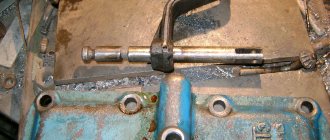
The procedure for repairing this mechanism:
- Disconnect the lower end of the handle from the rod.
- Remove the axle and lever.
- Pull the bushing out of the hole in the control handle.
- Remove the axle mechanism mounting pin.
- Pull out the axle and dismantle the drive gears along with the support washers and bearings.
- Remove the baffle from the shaft.
- Unscrew the front cover and remove the seal.
- Pull out the oil seal and remove the rear housing from the bearings.
- Remove the intermediate shaft, as well as the bearing located at the front of the cylinder block.
- Remove the mounting screw from the driven shaft and pull it out along with the gear assembly.
- Knock out the crankcase hatch plug.
- Remove the protective cap from the stem.
- Pull out the rod, fork, locking and spring mechanisms.
- Unscrew the nut and remove the O-ring, washer and seal.
- Replace all worn and damaged parts.
- Before installation, lubricate all mechanisms with oil.
- Before starting the engine, fill the PTO with spindle oil.
In order to avoid damage to the PTO, it is recommended to carry out regular maintenance, the procedure for which is in the user manual.
Installation of additional power take-off
Installation of additional power take-off NL/1 or NL/4 at power take-off point “D”. (Requires adapter housing 1304 199 010)
Re-measure and install the tapered roller bearing.
1 Unscrew the 4 hexagon head screws (11) from the cover (9) and remove them (disappears). 2 Remove the mounting washer (8) and main washer (7). 3 Install the tapered roller bearing following the instructions above, but without the main washer (7). 4 Measure the distance from the seal to the bearing ring.
5 Measure the length of the centering collar on the adapter body.
6 The difference between both measurements corresponds to the thickness of the adjusting washer.
7 Select the adjusting washer (8) so that a preload of max. 0.15 mm or respectively max. 0.05 mm.
8 Place the adapter body on the positioned seal and connect NL/1 or NL/4 using another seal.
Tightening torque for M12 = 79 Nm.
Installation washers are delivered “S” thickness: 1232 304 115 = 2.95 mm 1232 304 118 = 3.10 mm 1232 304 093 = 3.25 mm 1232 304 096 = 3.40 mm 1232 304 099 = 3.55 mm 1232 304 304 102 = 3.70 mm 1232 304 105 = 3.85 mm 1232 304 108 = 4.00 mm 1232 304 110 = 4.10 mm
CAREFULLY
After installing the power take-off N.../10, it is necessary to fill the gearbox with an additional approximately 0.5 dm3 (0.5 l) of oil. Then turn on the engine for 3 minutes with the gearbox in neutral. After this, check the oil level in the gearbox again and, if necessary, top up before pouring.
Once the oil filling is complete, retighten all screw plugs on the transmission.
Tightening torque: M38x1.5 = 120 Nm. M24x1.5 = 50 Nm.
Connection diagram for KAMAZ | KAMAZ
Gearbox on a Kamaz car (switching diagram) for subscribers
Overview of the interior and controls of KAMAZ 65221)))
Dump truck Kamaz 55111 body lift
KAMAZ 43101 CONTROL-INSTRUMENTS
Cabin KAMAZ 43118 (part 2)
ZF gearbox on KamAZ 6520. Gear placement and shifting.
power take-off
Wiring on KAMAZ. Part 2. In the cockpit.
Switching the transfer case of KamAZ 4310
Everyday life of Kamaz drivers: Making music, voltage converter from 24 to 12 volts….
Also see:
- Conversion of onboard KAMAZ trucks into a dump truck
- Screw rotor based on KAMAZ
- Changing the oil in the rear axle gearbox of KAMAZ
- Cabin for KAMAZ Elekon
- Engine block KAMAZ 4310
- Paper model of KAMAZ 54115
- What are the dimensions of KAMAZ
- Pump for KAMAZ tractor
- KAMAZ 20 ton dump trucks
- My KAMAZ goes even in icy conditions
- KAMAZ food tanks
- Conversion of onboard to KAMAZ dump truck
- Almost 200 people eliminate the consequences of the train and KAMAZ accident
- KAMAZ trucks for ETS2
- Antifreeze KAMAZ volume
Home » Hits » Switching diagram for KAMAZ
kamaz136.ru
Blocking transmission
Blocking transmission
for clutch driven power take-offs for gearboxes: 9 S 1110 TD/TO and 9 S 1310 TO
NOTE
For some vehicles, it must be ensured that no gear can be engaged when the power take-off is engaged, or that the power take-off cannot be engaged when a gear is engaged. A ZF pneumatic transmission locking system can therefore be supplied for all clutch-driven power take-offs. The locking system locks the system of rods and levers and thus prevents improper control of the vehicle.
Explanation
1 Blocking valve (depending on the type of gearbox, different connections, valves and screws) 2 Power take-off
Cost of repair and replacement
When choosing a power take-off, you need to pay attention to the following characteristics: compactness and light weight, sufficient resource, ease of gear shifting, maintaining the required power, reducing fuel consumption, and increasing engine life. Thus, the price of a new power take-off for KAMAZ starts from 15,000-20,000 rubles. The upper limit of the cost of this unit is usually about 40,000 rubles, although it may exceed this figure. Used parts like these can be purchased even cheaper. In this case, KOM will cost, as a rule, less than 10,000 rubles. In Moscow, you can find this mechanism even for less than 5,000 rubles, but when choosing a used device, carefully check its condition, as well as the quality of all its elements.
Service centers set the following price for their services: repair - from 5,000 rubles, replacement - from 7,000 rubles.
Have you ever had to repair the power take-off yourself? What advice can you give to those who are faced with this problem?