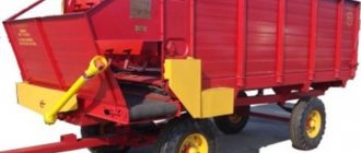
Since the process of automation has firmly taken hold of the agricultural process, feed dispensers have been increasingly used in work. It is very popular among farmers, which is based in the Moscow region. It produces a wide range of products, including fertilizer application equipment, trailers and feed distributors. One of the best-selling feed dispenser models is the KTU-10.
Feed dispenser KTU-10
The KTU-10 model is designed for processing and dosing feed mass, for harvesting agricultural crops in conjunction with harvesting machines, for unloading crushed feed into stationary dispensers, which are located in close proximity to animals, as well as for unloading mass into storage facilities. The KTU-10 feed dispenser has the following features:
- The design of the equipment is a towing device based on rubber wheels. The body is made of especially durable metal, and conveyors are mounted along the bottom.
- The chassis is as simple as possible, and it is equipped with hydraulic brakes. The entire braking system is controlled by the driver from the tractor with which the feed dispenser is mounted.
Uniform distribution of feed is ensured by a unique distribution mechanism, which consists of conveyors, belts, and beaters.
Purpose of the KTU-10A feed dispenser
The KTU-10A feed dispenser is designed to perform the following work:
- transportation and dosed distribution of crushed feed and ready-made feed mixtures to animals in feeders on one or both sides in livestock buildings or on walking areas;
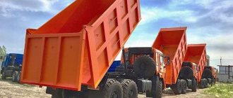
- transportation of products with unloading back;
- dosed supply of feed to on-farm stationary feed dispensers and feed storage facilities.
The feed dispenser is used in livestock buildings, on walking areas and summer camps, as well as when preparing feed as a vehicle. The technical characteristics of the feed dispenser are given in table. 1.
Table 1. Technical characteristics of the KTU-10A mobile feed dispenser
| Index | Meaning |
| Load capacity, kg | 3500 |
Capacity, m3:
| 10 15 |
| Feed, t/h | 20…50 |
Speed, km/h:
| 1,7…2,5 23 |
Dispensing capacity, kg/linear. m:
| 5,2…72 2,6…36 |
| Track, mm | 1600 ± 8 |
| Transport clearance, mm | 300 |
| Turning radius along the outer wheel track, mm | 6,5 |
| Minimum width of the stern passage, mm | 2000 |
| Maximum height of feeders, mm | 750 |
| Overall dimensions, mm | 6175-2300-2440/2090 |
| Weight, kg | 2380/2480 |
| Class of tractor with which the feed dispenser is mounted | 0,9…1,4 |
| Service personnel, persons | 1 |
Device
The main elements of the feed dispenser are:
- Body. Its rear sides are hinged, and the floor is finished with wooden boards.
- The chassis, consisting of a frame, axles, springs, as well as a towing mechanism, secured with hinges and having a towing loop.
- The longitudinal conveyor is a pair of parallel chains that move along the bottom of the body. It is driven by a drive shaft and a beater shaft.
- Beaters are the basis of the dispensing device.
- The braking system is based on the rear wheels. The blocks are driven by the tractor driver from the cab.
- Electrical equipment.
Diagram of the feed dispenser KTU-10
1 - bottom, 2 - rear board, 3 - side board, 4 - extension board, 5, 18 - enclosing panels, 6 - sidewall, 7 - beater block, 8 - reflector shield, 9 - front side, 10 - unloading conveyor , 11 – distributor drive, 12 – brake device, 13 – telescopic shaft, 14 – hydraulic mechanism for lifting an additional conveyor, 15 – chassis, 16 – additional conveyor, 17 – rear light and turn signal.
Spare parts for feed dispensers
for feed dispensers
We sell spare parts for feed dispensers KTU-10, RKT-10, KT-6, KT-10, KT-10-01, KTP-6, KTP-10 from a warehouse in Voronezh at low prices.
You can check the production time and cost of spare parts with the managers of Ros-Agro LLC
| №.№. p/p | Proposed products | Designation | Weight products | |
| SPARE PARTS FOR FEED DISPENSERS | ||||
| 1 | Conveyor for feed mill KORK-15 | TS-40.OM | 42kg. | |
| 2 | Conveyor for feed mill KORK-15 | TS-40.OS | 37kg. | |
| 3 | Longitudinal conveyor with anchor chain | RMM.00.1280-03 | 53.2kg. | |
| 4 | Conveyor with bushing and roller chain | RMM.00.230 | 49kg. | |
| 5 | Cross rubber conveyor | RMM.00.040-05 | 8.5kg. | |
| 6 | Short transverse rubber conveyor | KTU-9-11/2-sided | 6kg. | |
| 7 | Long transverse rubber conveyor | KTU-9-11-01 | 12kg. | |
| 8 | Short transverse rubber conveyor | KT-6. 23.000SAT | 5kg. | |
| 9 | Long transverse rubber conveyor | KT-6. 03.000SAT | 9kg. | |
| 10 | Longitudinal conveyor with anchor chain | KTU.50.0220-10 | 9kg. | |
| 11 | Longitudinal conveyor with roller chain | PTV-2.4M | 62 kg. | |
| 12 | Longitudinal conveyor with anchor chain | KT-10.04.060SB | 62kg. | |
| 13 | Longitudinal conveyor with roller chain | KT-10.04.100SB | 60kg. | |
| 14 | Longitudinal conveyor with anchor chain | KT-6.04.150SB | 53kg. | |
| 15 | Longitudinal conveyor with roller chain | KT-6.04.160SB | 48kg. | |
| 16 | Conveyor to ROU-6 | ROM.00.1270 | 60kg. | |
| 17 | Sprocket driven/leading to ROU-6 | PIN-01.118A/PIN-01.117B | 4kg. | |
| 18 | Shaft leading to the ROU-6 conveyor | 4kg. | ||
| 19 | Turning circle | RKT-10(2PTS-4) | 44kg. | |
| 20 | Distributing table for KTU-10 is one-sided | KTU.55.1091 | 92kg. | |
| 21 | Distributing table for KTU-10 double-sided | KTU.55.1092 | 93kg. | |
| 22 | Drive shaft of the transverse conveyor | KTU.00.6002-1 | 5.1kg. | |
| 23 | Transverse conveyor drive shaft driven | KTU.00.6002-2 | 5.1kg. | |
| 24 | Cross drive drive shaft assembly | KTU.50.4050-1 | 10kg. | |
| 25 | Transverse drive driven shaft assembly | KTU.50.4050-2 | 10kg. | |
| 26 | Shaft No. 6 assembled | KTU.50.5850 | 13kg. | |
| 27 | Shaft No. 6 | KTU.00.6025 | 6.8kg. | |
| 28 | Drive unit | KTU.50.3770 | 11kg. | |
| 29 | Beater drive shaft assembly | KTU.50.1470 | 12kg. | |
| 30 | Beater drive shaft | KTU.50.6046 | 9kg. | |
| 31 | KT-10 bushing-roller shaft | KT-10.04.170 | 40kg. | |
| 32 | KT-10 anchor shaft | KT-10.04.110 | 40kg. | |
| 33 | KT-6 bush-roller shaft | KT-6.04.170 | 38kg. | |
| 34 | KT-6 anchor shaft | KT-6.04.110 | 37kg. | |
| 35 | Shaft (anchor) | KTU-50.0900 | 35kg. | |
| 36 | Shaft (bush-roller) | KTU-50.0900 | 29kg. | |
| 37 | Beater drive shaft | KT.6.05.603 | 7.5kg. | |
| 38 | Beater drive shaft assembly | KT.6.05.010 | 17kg. | |
| 39 | Beater drive shaft | KT.10.05.611 | 8kg. | |
| 40 | Beater drive shaft assembly | KT-10 05.010 | 17.5kg. | |
| 41 | Drive shaft of longitudinal conveyors | KTU.50.6001 | 18kg. | |
| 42 | Cardan shaft | KTU.50.0560 160 n.m. | 15kg. | |
| 43 | Cardan shaft | KT-6, KT-10 160 n.m. | 13kg. | |
| 44 | Drive shaft of longitudinal conveyors | KT.10.04.601 | 19kg. | |
| 45 | Drive shaft of longitudinal conveyors | KT.6.04.603 | 17kg. | |
| 46 | Shaft | KTU.50.6002 | 16.5kg. | |
| 47 | Crank drive shaft assembly | KTU.50.6350 | 26.5kg. | |
| 48 | Crank drive shaft | KT.10.05.034 | 48kg. | |
| 49 | Eccentric drive shaft assembly | KT 10.05.022 | 28kg. | |
| 50 | Crank drive shaft | KT.6.05.031 | 15kg. | |
| 51 | Rear axle of longitudinal conveyor | KTU.00.678.02 | 7kg. | |
| 52 | Rear longitudinal conveyor shaft | KT.10.04.602 | 9kg. | |
| 53 | Rear longitudinal conveyor shaft | KT.6.04.604 | 8kg. | |
| 54 | Anchor chain | 1A 9x27 | 2kg. | |
| 55 | Bush-roller chain | TRD-38-3000-2-6 | 2.3kg. | |
| 56 | Bush-roller chain | PR-19.05-31.8 | 5.01-6.0kg. | |
| 57 | Bush-roller chain | PR-25.4-60 | 1.78-4.8 kg. | |
| 58 | Connecting chain link (lock) | 19,05; 25,4; 38,1 | 0.05kg. | |
| 59 | Sprocket block (per beater block) | 50180 | 4.0kg. | |
| 60 | Drive sprocket (anchor chain) | KTU.00.124 | 2.7kg. | |
| 61 | Drive sprocket (anchor chain) KT10; KT-6 | KTF.12.05.301 | 4kg. | |
| 62 | Driven sprocket (anchor chain) | KTU.00.125 | 2.7kg. | |
| 63 | Driven sprocket (anchor chain) KT10; KT-6 | KTF.12.05.302 | 2.7kg. | |
| 64 | Drive sprocket (bush-roller chain) | PTV-202-2-4 | 1.36kg. | |
| 65 | Drive sprocket (bush-roller chain) | KT.10.04.140 | 2.7kg. | |
| 66 | Drive sprocket (bush-roller chain) | KT.6.04.190 | 3.0kg. | |
| 67 | Driven sprocket (bush-roller chain) | PTV 1006 | 1.22kg. | |
| 68 | Driven sprocket (bush-roller chain) | KT.10.04.160 | 2.45kg. | |
| 69 | Driven sprocket (bush-roller chain) | KT.6.04.200 | 3.0kg. | |
| 70 | Beater drive sprocket | KTU.00.6042 | 0.8kg. | |
| 71 | Beater drive sprocket | KT.10.05.071 | 1.45kg. | |
| 72 | Beater drive sprocket | KT.6.05.060(KTU00.0870 | 1.9kg. | |
| 73 | Beater sprocket | KTU.50.0190 | 2.5kg. | |
| 74 | Beater block sprocket | KT.6.06.090 | 1.9kg. | |
| 75 | Beater block sprocket | KT.6.06.080 | 1.7kg. | |
| 76 | Beater block sprocket | KT.6.06.070 | 1.1kg. | |
| 77 | Cross table drive sprocket | 9.15 | 3kg. | |
| 78 | Reducer drive sprocket | KTU.00.664 | 0.62kg. | |
| 79 | Table drive chain tension sprocket | KT.6.05.040(960/01) | 0.9kg. | |
| 80 | Tension sprocket assembly for beater drive | KTU-00.1030-01A | 0.8kg. | |
| 81 | Crank drive shaft sprocket | KT.6.05.070(KTU.00.450) | 3.5kg. | |
| 82 | Crank | KTU.00.1490 | 1.65kg. | |
| 83 | Ratchet wheel | KTU.50.6005 | 10.1kg. | |
| 84 | Scraper | PTV, KTU | 1.9kg. | |
| 85 | Lid | 1073,1071,N.026164 | 0.75kg. | |
| 86 | Lid | 113 | 0.75kg. | |
| 87 | Bearing shell | KTU.00.102 | 1.5kg. | |
| 88 | Bearing shell | N.26059 | 1.4kg. | |
| 89 | Bearing shell | KTU.55.4495 | 0.3kg. | |
| 90 | Bearing shell | 1072 | 1.5kg. | |
| 91 | Beater side | KTU.50.1680 | 1.5kg. | |
| 92 | Beater side | KTU.50.5140 | 13.95kg. | |
| 93 | Sidewall of the transverse conveyor | KTU.50.2050A/KTU.50.2040A | 13.95kg. | |
| 94 | Table 2-sided/1-sided | KTU.50.4040A/KTU.50.4050 | 7.2/20.9 kg. | |
| 95 | Visor | KTU.50.4423 | 1.6kg. | |
| 96 | Tensioner | KTU.55.5500 | 0.53kg. | |
| 97 | Anchor chain lock | 1A 9x27 | 0.05kg. | |
| 98 | Wheel disk | 331013 | 15kg. | |
| 99 | Spring | KTU.00.6008 | ||
| 100 | Spring | PTV-6228 | ||
| 101 | Beater KT-6 top/bottom. | KT-6.06.030/KT-6.06.040 | 38kg. | |
| 102 | Beater KT-10-01 (KTU) | KTU.50.1660 | 50kg. | |
| 103 | Beater KT-10 lower | KT-10.06.031-01 | 50kg. | |
| 104 | Beater KT-10 upper | KT-10.06.031 | 54kg. | |
| 105 | Beater block | KTU.50.1670 | ||
| 106 | Lever arm | KTU.50.4054/50.3780 | 1.5kg. | |
| 107 | Spring | 887A-2902012 | 35kg. | |
| 108 | 1st leaf spring | 2PTS-4 | ||
| 109 | Gearbox | N.091.20.000A-113 | 34kg. | |
| 110 | Hub with bearing | 3103010 | 15kg. | |
| 111 | Dog | PTV-6006 | 0.65kg. | |
| 112 | Flange | PTV 6025 | 0.45kg. | |
| 113 | connecting rod | KTU.50.2980 | 2kg. | |
| 114 | Ladder | 887A-2912408 | 1.46kg. | |
| 115 | Agricultural tires | 240x406(9x16) | 31.5kg. | |
| 116 | Car camera | 240x406(9x16) | 31kg. | |
| 117 | Bearing | KTU.00.1310-01 | 1.1kg. | |
| 118 | Bearing | KTU.50.0330 | 2.05kg. | |
| 119 | Bearing | KTU.50.5330 | 3.0kg. | |
| 120 | Bearing | 180206 | 0.21kg. | |
| 121 | Bearing | 11207 | 0.55kg. | |
| 122 | Bearing | 1508 | 0.42kg. | |
| 123 | Bearing | 7609 | 1.7kg. | |
| 124 | Bearing | 7611 | 2.2kg. | |
| 125 | Bearing | 308 | 2.2kg. | |
| 126 | Half coupling for shaft No. 6 | KTU.6007-A | 0.25kg. | |
| 127 | Half coupling for shaft No. 6 | KTU.00.1930 | 1.125kg. | |
| 128 | Half-coupling assembly for shaft No. 6 | KTU.00.1940 | 1.05kg. | |
| 129 | Washer | KTU.00.042 | ||
| 130 | Ice rink | KTU.00.22A | ||
Operational Features
Before use, the feed dispenser should be run in for half an hour. You should start with low speed, and then switch to normal. The KTU-10 model is aggregated with the Belarus tractor.
The equipment is loaded with feed mass evenly. To distribute feed, you must turn on a special operating mode, and the gear lever must be moved to 1st or 2nd gear.
The vehicle body is designed so that feed distribution is possible on both sides of the body. For one-sided distribution, one transport sheet is required, and for two-sided distribution, two.
To use the feed dispenser as a transport device, the ratchet mechanism must be activated, and for self-unloading, a special arrangement of pawls and discs is used. This agricultural machinery allows you to regulate the supplied feed mass by changing the speed of the conveyor.
At sub-zero temperatures, the feed dispenser must be kept in a warm room to avoid the formation of ice on conveyors and other moving mechanisms.
The device of the feed dispenser KTU-10A
The feed distributor KTU-10A (Fig. 1) is a two-axle tractor trailer on springs and pneumatic wheels 15. The machine consists of a frame 1 with a body mounted on it, at the bottom of which there are two longitudinal chain-slat conveyors 10, designed to move a layer of feed from the rear 2 to the front 9 wall of the body.
For dosed feeding of feed, in the front part of the body, in front of the longitudinal conveyors 10, a block of beaters 7 is installed, behind which a transverse conveyor 16 is located.
The drive of the working bodies is carried out by cardan shaft 13 through kinematic transmissions from the power take-off shaft (PTO) of the tractor.
On the frame 1 with the chassis 15 there is a link 12, a braking device and electrical equipment. The hook 12 is connected at one end to a rotary hinge, and at the other there is a tow hook.
A
b
Rice. 1. General view (a) and diagram (b) of the KTU-10A feed dispenser: 1 – frame; 2 – rear side; 3 – side board; 4 – extension board; 5 – fencing panels; 6 – sidewall; 7 – block of beaters; 8 – reflector shield; 9 – front side; 10 – longitudinal conveyor; 11 – distributor drive; 12 – snitch; 13 – telescopic shaft; 14 – hydraulic mechanism for lifting an additional conveyor; 15 – chassis; 16 – transverse (additional) conveyor; 17 – rear light and turn signal
The rear wheels are equipped with hydraulically driven shoe brakes, which are controlled from the tractor driver’s cab.
The body is all-metal with a hinged tailgate 2. The bottom of the body is made in the form of a metal frame along which two pairs of chain-slat longitudinal conveyors 10 slide, forming two canvases. They serve to supply feed to the beaters 7.
The longitudinal conveyor (Fig. 2) consists of two pairs of chains 1, to which stamped transverse metal strips 2 are attached by means of a clamp 5, washer 4 and nut 3. Each pair of chains with strips forms a conveyor belt.
The conveyor belts are fixed by means of sprockets 6 on one drive shaft 7 and move intermittently, which ensures a uniform supply of feed to the beaters 8.
Rice. 2. General view (a) and diagram (b) of the longitudinal conveyor: 1 – chain; 2 – strips; 3 – nut; 4 – washer; 5 – clamp; 6 – asterisk; 7 – drive shaft; 8 – beater
The drive shaft 7 of the longitudinal conveyor is located in the front part of the body and rotates in four plain bearings. It is driven into rotation from the lower beater shaft 8 through a crank mechanism.
In the front upper part of the body (see Fig. 1) there is a block of beaters 7, which is designed to uniformly supply feed to the transverse conveyor 16. The beaters are shafts with radial pins arranged in a checkerboard pattern and rotate in bearings mounted on the sidewalls 3 body
Also in front, but slightly below the longitudinal conveyor 10 and perpendicular to it, there is a transverse unloading conveyor (Fig. 3), which serves to supply feed to the feeders. It consists of a driving shaft 1 and a driven shaft 2, a rubberized tape 3 with strips. Can distribute feed into feeders located on one side or on both sides of the dispenser.
Rice. 3. Transverse unloading conveyor: 1 – drive shaft; 2 – driven shaft; 3 – rubberized tape
To distribute feed into high feeders, the dispenser is equipped with an additional conveyor, which is hung on the unloading part of the transverse conveyor. The additional conveyor is installed in the required position using a hydraulic mechanism and secured with supporting chains. If it is no longer needed, it will be dismantled.
Metered feed supply is ensured by a block of beaters. The beater (Fig. 4) consists of a shaft 1 with hexagonal disks fixed on it, to the planes of which a shell 2 is welded. To loosen the feed, fingers 3 are attached to the shell 2.
The rate of feed dispensing is regulated by changing the speed of the longitudinal conveyor 10 (see Fig. 1) and the forward speed of the tractor. The mechanism for regulating the amount of feed unloaded into the feeders consists of a crank and ratchet mechanisms, and a chain drive.
Rice. 4. General view (a) and diagram (b) of the beater block: 1 – shaft; 2 – shell; 3 – finger
The ratchet mechanism (Fig. 5, a) consists of a connecting rod 3, a ratchet wheel 5, an earring 2, movable 6 and fixed 8 pawls, springs for holding the pawls in a given position and a sector of the ratchet wheel 5. The speed of movement of the longitudinal conveyor depends on the number of ratchet teeth wheels 5, captured by working pawl 6 in one revolution of the shackle 2.
The longitudinal conveyor is driven by a crank ratchet mechanism from the tractor PTO. When the tractor PTO is turned on, the crank body 1 together with the linkage 2 rotates, through the connecting rod 3 the rocker arm 4 is set into oscillatory motion, on which the pawl 6 is attached, pressed to the ratchet wheel by a spring.
Ratchet wheel 5 is fixed to the drive shaft 7 of the longitudinal conveyor. When the connecting rod 3 makes an idle movement, the pawl 6 slides along the teeth of the ratchet wheel 5. During the working movement, the pawl 6 rests against the tooth of the ratchet wheel 5, thereby turning the conveyor shaft 7. The safety pawl 8 keeps the ratchet wheel 5 from reverse rotation.
Rice. 5. Longitudinal conveyor drive: a – ratchet mechanism with conveyor; b – ratchet mechanism assembly; c – parts of the ratchet mechanism; 1 – crank body; 2 – earring; 3 – connecting rod; 4 – rocker arm; 5 – ratchet wheel; 6 – movable pawl; 7 – drive shaft; 8 – fixed pawl; 9 – conveyor
The speed of the longitudinal conveyor, and therefore the amount of feed supplied, is regulated by changing the angle of rotation of the drive shaft of the longitudinal conveyor, i.e., by changing the number of working teeth of the ratchet wheel 4 (Fig. 6). The latter depends on the position of disk 3.
Setting the ratchet mechanism to the feed dispensing rate is done by installing the ratchet wheel casing lock in the sector opposite the corresponding scale division. In this case, the pawls associated with the crank mechanism rotate the ratchet wheel to the required angle for each stroke.
For example, in the “max feed” position, the movable pawl 2 will engage with the wheel earlier than in other positions: the number of working teeth is greatest, which means that the speed of the longitudinal conveyor is also greater.
Rice. 6. Diagram of operation of the longitudinal conveyor drive ratchet mechanism: a – when the conveyor moves forward; b – when the conveyor moves backwards; 1 – connecting rod; 2, 5 – movable and fixed pawls; 3 – eccentric disk; 4 – ratchet wheel; 6 – sector; 7 – lever
The ratchet mechanism ensures the movement of the longitudinal conveyor forward when distributing feed and backward when the feed dispenser is operating to transport various loads. To convert the feed dispenser into a self-unloading trailer, it is necessary to install pawls 2, 5 and disk 3 according to the diagram (see Fig. 6, b) and fix lever 1 in the “Back” position. Before unloading, you must open the tailgate and use spacers to set it in the open position.
The working parts of the dispenser are driven from the tractor power take-off shaft through the cardan shaft 1 of the feed dispenser (Fig. 7). Rotation from the cardan shaft 1 is transmitted to drive 2 and, through a chain transmission 3, to the drive shaft of the transverse conveyor 4.
The drive shaft 2 is connected to a bevel gearbox installed under the bottom of the body, from which rotation through the longitudinal shaft and chain drive 5 is supplied to the lower beater shaft 6. A second sprocket is installed on the lower beater shaft 6, connected by a chain drive 7 to the upper beater 8.
A
A
b
Rice. 7. Drive of the working parts of the feed dispenser KTU-10A: a – general view of the drive of the working parts of the feed dispenser; b – kinematic diagram of the drive of the working parts of the feed dispenser; 1 – cardan shaft; 2 – drive; 3, 5, 7 – chain drive; 4 – drive shaft of the transverse conveyor; 6 – lower beater; 8 – upper beater; 9 – asterisk; 10 – drive shaft of the longitudinal conveyor; 11 – crank mechanism
On the shaft of the lower beater 6 (see Fig. 7) there is a connecting rod 1 (see Fig. 1), which transmits rotation to a ratchet wheel mounted on the intermediate shaft.
A sprocket 9 mounted on the intermediate shaft on the opposite side transmits rotation to the drive shaft of the longitudinal conveyor 10.
The kinematic diagram of the drive of the working parts of the feed dispenser is shown in Fig. 7, b. The feed dispenser drive includes a cardan shaft, a dispenser drive shaft, drives for transverse and longitudinal conveyors and beaters.
Specifications
Technical characteristics of the KTU-10 feed dispenser:
| Characteristics | Indicators | Unit measurements |
| Length | m | 6,67 |
| Width | m | 2,3 |
| Height | m | 2,5 |
| Wheelbase | m | 2,75 |
| Weight | T | 2,1 |
| Clearance | cm | 30 |
| Speed | km/h | 30 |
| Tires | mm | 12-16 |
| Load capacity | T | 4 |
| Performance | m3/h | 72-480 |
| Power | kW | 7,5 |