The turbocharging system in a car engine is used to increase power. Thanks to it, car manufacturers can seriously increase the capabilities of equipment (speed, load capacity, cross-country ability) without significantly increasing weight and increasing fuel consumption.
Below in this article we will answer the questions: how does a diesel car turbine work? At what speed does it turn on? We will also debunk some well-known myths associated with turbocharged engines. Users can learn more about the operation of the turbocharging system by going to the KTSrvis company website; here you can also order a service for the repair and maintenance of diesel engines with turbines.
Basic principles of turbo engine operation.
As you know, engine power is proportional to the amount of air-fuel mixture entering the cylinders. All other things being equal, a larger engine will allow more air to flow through it and therefore produce more power than a smaller engine. Whether we want a small engine to produce as much power as a large one, or we simply want a large one to produce even more power, our main goal will be to put more air into the cylinders of that engine. Naturally, we can modify the cylinder head and install sports camshafts, increasing the purging and the amount of air in the cylinders at high speeds. We can even leave the amount of air the same, but raise the compression ratio of our engine and switch to a higher octane fuel, thereby increasing the efficiency of the system. All these methods are effective and work when the required increase in power is 10-20%. But when we need to radically change the engine power, the most effective method is to use a turbocharger. How will a turbocharger allow us to get more air into the cylinders of our engine? Let's take a look at the diagram below:
Turbocharging system design
The turbocharging system consists of two parts: a turbine and a turbocharger. The turbine is used to convert the energy of exhaust gases, and the compressor is used directly to supply repeatedly compressed atmospheric air into the working cavities of the cylinders. The main parts of the system are two blade wheels, a turbine and a compressor (the so-called “impellers”). A turbocharger is a high-tech air pump driven by the rotation of a turbine rotor. Its only task is to pump compressed air into the cylinders under pressure.
The more air enters the combustion chamber, the more diesel fuel the diesel engine can burn in a specific unit of time. The result is a significant increase in engine power, without the need to increase the volume of its cylinders.
Components of the turbocharging device:
- compressor housing;
- compressor wheel;
- rotor shaft, or axis;
- turbine housing;
- turbine wheel;
- bearing housing.
The basis of the turbocharging system is a rotor mounted on a special axis and enclosed in a special heat-resistant housing. The continuous contact of all components of the turbine with extremely hot gases determines the need to create both the rotor and the turbine housing from special heat-resistant metal alloys.
The impeller and turbine axis rotate at very high speeds and in opposite directions. This ensures that one element is pressed tightly against another. The flow of exhaust gases first penetrates the exhaust manifold, from where it enters a special channel located in the turbocharger housing. The shape of its body resembles the shell of a snail. After passing through this “snail”, the exhaust gases are accelerated and supplied to the rotor. This ensures forward rotation of the turbine.
The turbocharger axis is mounted on special plain bearings; Lubrication is carried out by supplying oil from the engine compartment lubrication system. O-rings and gaskets prevent oil leaks, as well as air and exhaust gases from blowing through and mixing. Of course, it is not possible to completely eliminate exhaust from entering the compressed atmospheric air, but this is not really necessary...
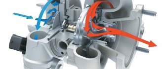
Let's look at the main stages of air flow in an engine with a turbocharger:
— The air passes through the air filter (not shown in the diagram) and enters the inlet of the turbocharger (1) — Inside the turbocharger, the incoming air is compressed and at the same time the amount of oxygen per unit volume of air increases. A side effect of any air compression process is that it heats up, which somewhat reduces its density. — From the turbocharger, the air enters the intercooler (3) where it cools and largely restores its temperature, which, in addition to increasing air density, also leads to a lesser tendency for our future air-fuel mixture to detonate. — After passing through the intercooler, the air passes through the throttle, enters the intake manifold (4) and then, on the intake stroke, into the cylinders of our engine. The volume of the cylinder is a fixed value determined by its diameter and stroke, but since it is now filled with air compressed by a turbocharger, the amount of oxygen entering the cylinder becomes significantly greater than in the case of an atmospheric engine. A larger amount of oxygen allows you to burn more fuel per stroke, and the combustion of more fuel leads to an increase in the power produced by the engine. — After the fuel-air mixture has burned in the cylinder, it goes into the exhaust manifold (5) during the exhaust stroke, where this stream of hot (500C-1100C) gas enters the turbine (6) — Passing through the turbine, the flow of exhaust gases rotates the shaft turbine on the other side of which there is a compressor, and thereby does the work of compressing the next portion of air. In this case, a drop in pressure and temperature of the exhaust gas occurs, since part of its energy was spent on ensuring the operation of the compressor through the turbine shaft.
What are the engine turbine speeds?
Good day to all. Since I recently became the owner of a turbocharged car, I asked myself the question of how to properly operate the turbine in order to protect myself from breakdowns and extend the service life of both the turbine and the engine as a whole. In this post, I tried to squeeze out as much as possible all the most important things from all the articles that I read about turbines and present them for you in About turbines in general
Turbines are installed on both gasoline and diesel engines.
Some manufacturers use low boost turbines. The pressure that such a turbine creates is low; its main purpose is to create turbulent air flows, which contribute to better mixing of gasoline with fuel. High pressure turbines are much more efficient. For engines with a high-pressure turbine, the liter power can be one and a half times higher than that of an atmospheric counterpart. But its design is a little more complicated. To ensure that excess pressure at high speeds does not damage the engine, engineers came up with a special valve to eliminate excess pressure. For many turbo engines, an intercooler is a must. Its task is to cool the air heated by the turbine. Cold air contains more oxygen for the same volume. Modern injection systems make it possible to almost completely get rid of the phenomenon of “turbo lag” (a loss of power when the gas is sharply pressed), characteristic of older engines. In the process of turbine evolution, virtually all the disadvantages of turbo engines were eliminated. Many, both through the use of two turbines for low and high speeds, and through the use of turbines with variable performance - such turbines have the ability to change the inclination of the discharge (compression) blades. As a result, we got engines with high liter power with compact sizes of the units themselves. About the operation of the turbine
The turbine blades, under the influence of exhaust gases, rotate at enormous speed - more than one hundred thousand revolutions per minute.
The axis, which is driven by the drive impeller, is attached using plain bearings to the turbine housing. To lubricate the bearings, motor oil is used, which is supplied under pressure. As soon as the engine stops working, the oil pressure drops sharply, and both impellers, drive and discharge, continue to rotate by inertia. The bearings of the shaft on which both impellers are mounted are left without lubrication. Due to such overloads, the turbine begins to “eat” oil. Through the increased gap, lubricant seeps under the discharge impeller and enters the intake manifold, and then burns in the cylinders. When the gap increases too much, the turbine begins to howl. In addition, the turbine cannot maintain high speeds for a long time without the supply of an appropriate amount of exhaust gases. Therefore, wear from oil starvation in a rolling bearing is accompanied by other side factors. For example: after prolonged operation of the engine with decent power output, the turbine housing becomes very hot from the large amount of hot exhaust gases passing through it. Most often, the turbine is cooled by the flow of the same engine oil. If the flow of this flow is stopped, when the engine is stopped, the remaining lubricant will certainly burn onto the turbine parts, which will lead, over time, to the accumulation of soot and inevitable wear of the parts. In this case, it is fair to decide to use higher quality oil; there will be a greater chance of survival. A good solution to maintain the operation of the turbine would be to use a so-called turbo timer. The device provides an automatic delay in turning off the engine after turning off the ignition for a time sufficient for the turbocharging parts to cool down. Many models of turbo timers even have an indication of the turbine temperature and the time required for the turbine to cool down. The turbo timer can be used either separately or in conjunction with a car alarm. The disadvantage of using it is that if there is a possibility of overheating of the turbine, the timer can turn it off at the most inopportune moment. And in addition to speed, you also have to control the operation of the turbine. About breakdowns
DAMAGE WHEN ENTERED BY FOREIGN PARTICLES Damage caused by foreign objects entering through the turbine or compressor housing. Such damage is clearly visible on the turbine impeller and compressor impeller. It is prohibited to use a turbocharger with damaged impellers, as Damage causes rotor imbalance, which can lead to complete destruction of the turbocharger and lead to serious engine damage.
INSUFFICIENT OIL SUPPLY Insufficient oil supply may have the following reasons: • unqualified installation of the turbocharger; • long engine downtime; • the oil supply tube is damaged or clogged; • low oil pressure due to malfunctions in the lubrication system; • low oil level or its absence in the crankcase; • the use of sealants that can get into the oil supply channels and block or limit the flow of oil; • an oil filter that is not filled with oil when changing the oil (it is advisable to “crank” the engine to create oil pressure); • starting the engine when the oil channels are not yet completely filled.
CONTAMINATED OIL Damage due to contaminated oil Typically appears as deep scratches on the bearings and shaft. To prevent such damage, use high-quality oil and filters recommended by the OE manufacturer. In addition to routine maintenance according to the vehicle specifications, oil and filters must be changed when changing the turbocharger. Causes of damage due to dirty oil may include: • damaged, clogged or poor quality oil filter; • dirt introduced during service work; • engine wear or wear particles; • non-functioning oil filter bypass valve; • oil with reduced lubricating properties.
CARBON PLATE Malfunctions caused by the formation of carbon deposit Plaque occurs due to increased exhaust temperature or stopping the engine immediately after stopping movement. It is recommended to let the engine idle for 2-3 minutes before turning off the engine so that the turbocharger bearing system has time to cool down. Heat from the turbine side penetrates the bearing housing, causing carbonation of the oil and deposits in the bearing system. The main damage occurs to the shaft in the area of the oil ring, the bearing closest to the turbine, and the oil channels in the bearing housing are blocked. Possible causes of oil carbonation: • stopping the engine immediately after stopping movement; • low quality oil; • irregular oil changes lead to its damage; • air and exhaust leaks; • problems with the fuel system (injectors, pumps, etc.)
Blow-off
A blowoff valve is a device installed in the air system between the compressor outlet and the throttle valve to prevent the compressor from entering surge mode. At moments when the throttle closes sharply, the flow rate and air flow in the system drops sharply, while the turbine continues to rotate for some time by inertia at a speed that does not correspond to the new dropped air flow. This causes cyclic pressure surges behind the compressor and an audible characteristic sound of air rushing through the compressor. Surge eventually leads to failure of the turbine support bearings due to the significant load on them in these transient conditions. BlowOff uses a combination of manifold pressure and manifold spring to determine when the throttle closes. In the event of a sharp closing of the throttle, the blowoff releases the excess pressure arising in the air path into the atmosphere and thereby saves the turbocharger from damage.
Why the turbine may not turn on - malfunctions
When driving a car with a turbocharging system, the driver may encounter many problems and malfunctions. Let's look at the main problems and methods for solving them:
- Safety valve malfunction . It happens that the valve becomes clogged with debris or cracks, which leads to blocking the operation of the turbine. It is quite simple to establish a breakdown - up to approximately 3-4 thousand revolutions, the valve can still work, so it will pump air. However, if this indicator is exceeded, it abruptly closes the turbine, which leads to a drop in power. To solve the problem, turn off the car's electronic systems, open the hood, disconnect the negative terminal from the battery, find the turbine, turn off the lubrication system and remove the device (usually it is located next to the engine). Then remove the valve and inspect it, if necessary, clean the device or replace it.
- Leaky fastening of turbocharging components . To ensure maximum air injection power into the internal combustion engine, it is necessary that the turbine parts are hermetically attached to the vehicle. In the case of a leaky fastening, the pumping power drops sharply. The presence of a problem can be determined by two signs - a sharp decrease in power and the appearance of a characteristic whistle while the car is running. To deal with the problem, you need to turn off the power to the car, open the hood and check the tightness of the device. Problems may arise with the fitting, oil supply pipe, valve, and so on. To fix the problem, you need to restore the tightness (for example, if the problem is in the fitting, you need to buy a new one).
- Using bad oil . For the turbocharging system to operate effectively, the device must be lubricated with oil. However, it happens that the driver uses cheap, low-quality oil with a lot of impurities for lubrication - in this case, the efficiency of turbocharging will significantly decrease. It is very easy to identify the problem - while the car is moving, a sharp loud grinding noise appears in the car, and the engine power does not increase when accelerating to high speeds. The solution to the problem is to buy new high-quality oil and pour it into the car instead of the old one.
Wastegate:
It is a mechanical valve installed on the turbine part or on the exhaust manifold and provides control over the pressure created by the turbocharger. Some diesel engines use turbines without wastegates. However, the vast majority of gasoline engines definitely require it. The main purpose of a wastegate is to allow exhaust gases to exit the system bypassing the turbine. By letting some of the gases bypass the turbine, we control the amount of gas energy that goes through the shaft to the compressor and, thereby, control the boost pressure created by the compressor. Typically, a wastegate uses boost pressure and internal spring pressure to control the bypass flow of exhaust gases. The built-in wastegate consists of a damper built into the turbine housing (scroll), a pneumatic actuator, and a link from the actuator to the damper. The external gate is a valve installed on the exhaust manifold before the turbine. The advantage of an external gate is that the bypass flow it dumps can be returned to the exhaust system far away from the turbine exit, or even dumped into the atmosphere on sports cars. All this leads to improved passage of gases through the turbine due to the absence of multidirectional flows in the compact volume of turbine housing.
How does turbocharging work?
To understand how turbocharging works, you first need to understand the concepts of turbo boost and turbo lag.
Turbo boost is a situation when the rotor, which has picked up speed, increases the flow of air into the cylinders, resulting in an increase in engine power.
Turbojam is a moment of slight delay observed in the operation of the turbine when the amount of incoming fuel increases, which is achieved by pressing the gas pedal. The delay is caused by the time it takes for the rotor to accelerate with gases.
Turbocharging increases the pressure of exhaust gases due to more intense engine operation. At the same time, the boost pressure also increases: this process requires monitoring and adjustment, since when high values are reached, there is a high probability of breakdown. The pressure regulation functions are assigned to the valve; the maximum possible values are controlled by a membrane and a spring with certain stiffness values (when the maximum permissible value is reached, the membrane opens the valve).
The operation of a diesel engine turbine also requires pressure control:
- The compressor releases excess air taken in through a valve to reduce pressure;
- when the pressure of the incoming air reaches the maximum permissible value, the valve releases the gases, and the rotor rotates at the required speed, and the compressor always takes in only the required amount of air.
Water and oil supply:
Garrett ball bearing turbines require significantly less oil than their bushing counterparts. Therefore, installing an oil restrictor at the turbine inlet is highly recommended if the oil pressure in your system exceeds 4 atm. The oil drain must be placed in a pan above the oil level. Since oil drains from the turbine naturally under the influence of gravity, it is critical that the center cartridge of the turbine is oriented with the oil draining downward. A common cause of turbine failure is oil coking in the central cartridge. A quick stop of the engine after large, prolonged loads leads to heat exchange between the turbine and the heated exhaust manifold, which, in the absence of an influx of fresh oil and cold air entering the compressor, leads to a general overheating of the cartridge and coking of the oil present in it. To minimize this effect, the turbines were equipped with water cooling. Water hoses provide a siphon effect, reducing the temperature in the central cartridge even after stopping the engine, when there is no forced water circulation. It is also desirable to ensure a minimum of vertical unevenness of the water supply line, as well as slightly rotate the central cartridge around the turbine axis at an angle of up to 25 degrees.
Myths about turbocharging in the engine
There are many myths among drivers about the operation of the turbocharging system. Let's look at the main stereotypes and find out why they are false:
| Myth 1 – the turbocharging system can be removed at any time without negative consequences | The design and volumes of the internal combustion engine chamber are adapted to the use of the turbine. If you dismantle this device, the torque and power of the engine decreases, and fuel consumption increases |
| Myth 2 – turbocharged engines break down much more often than naturally aspirated ones | Turbine engines have the same shelf life as conventional naturally aspirated engines. To reduce the risk of engine cracking at high speeds, they are additionally reinforced with metal sheets in problem areas |
| Myth 3 – the turbine quickly fails and will have to be replaced frequently | According to modern standards, the shelf life of a turbine is similar to or even slightly longer than the shelf life of the internal combustion engine itself. If you follow basic driving and maintenance rules, the turbo will last as long as the car itself. |
| Myth 4 – the turbine needs special careful care so that it does not break. | For turbocharging to work for a long time, it will be enough to adhere to the basic rules of car operation. Namely - change the oil on time, monitor the pressure level in the engine (do not bring it to the red line), troubleshoot problems in a timely manner |
In fact, the turbine always works, but at low speeds the air injection level will be low due to turbo boost.
Let's summarize. A turbine (turbocharging) is an auxiliary element of the engine, with the help of which air is forced into the internal combustion chamber of the engine. The device starts immediately after activating the engine, but the rule is that the higher the speed, the greater the boost (at low speeds the boost is almost imperceptible). The main problems with the turbine are valve failure, leaky fastening of spare parts, and the use of low-quality oil.
Turbine selection.
Correct selection of the turbine is a key point in building a turbo engine and is based on many input data. The most basic fact of choice is the power required from the motor. It is also important to choose this figure as realistically as possible for your engine. Since the power of the engine depends on the amount of the air-fuel mixture that passes through it per unit of time, having determined the target power, we will begin to select a turbine capable of providing the air flow necessary for this power. Another extremely important factor in choosing a turbine is the speed at which it reaches boost and the minimum engine speed at which this occurs. A smaller turbine or smaller hot housing can improve these figures, but the maximum power will be reduced. However, due to the larger operating range of the engine and the rapid release of the turbine to boost when opening the throttle, the overall result can be significantly better than using a larger turbine with high peak power, but in a narrow upper range of engine operation.
How does a diesel car's turbocharging system work?
The turbine is an auxiliary element of the internal combustion engine (internal combustion engine). It is used to force air masses into the working part of the engine. The use of a turbocharging system makes it possible to increase the power of the power plant, increase the speed characteristics of the car while maintaining standard fuel consumption standards.
Let's consider what the turbine design is and what are the basic principles of engine operation:
- A car moves on roads using the energy of fuel burned by an internal combustion engine.
- The engine transforms the energy of the fuel into kinetic energy, which starts the rotation of the wheels of the car.
- In addition to fuel, the engine chamber also contains oxygen; without it, fuel combustion is impossible.
- Oxygen penetrates into the power plant chamber from the atmosphere. When it comes to low-power units, the driver will not have problems. He will be able to squeeze everything possible out of such a motor. However, if the car owner wants to drive fast, then he needs a unit that can increase and increase the supply of oxygen and fuel to the chambers. If there are no problems with fuel (the driver has the ability to regulate its supply using injectors). It’s simply impossible to increase the oxygen supply. One of the options for solving the problem is enlarging the engine chambers. But in this case, the weight and dimensions of the vehicle will also increase. The second, more economical and practical method is to install a turbine.
Design and operation of the turbine:
- The turbine is a part made of metal in the form of a snail. It is installed on the exhaust manifold. The element may have different dimensions and weight, depending on the model of the machine.
- Inside the system there is a special rotor in the form of a cylinder with blades. As the exhaust gases pass through the rotor, the turbine starts to rotate.
- With the help of such rotation, air masses are forced into the chambers of the power plant. This increases the oxygen level and increases the power of the unit.
- An important element of the turbocharging system is the intercooler. It performs the function of cooling atmospheric air. This is necessary to increase the density of the mixture of fuel and oxygen.
Bushing and ball bearing turbines.
Bushing turbines have been the most common for a long time, however, newer and more efficient ball bearing turbines are being used more and more often. Ball bearing turbines have emerged as a result of Garrett Motorsport's work in many racing series. The turbo's throttle response is largely dependent on the design of the center cartridge. Garrett ball-bearing turbines provide 15% faster boost compared to their hub counterparts, reducing the effect of turbo lag and bringing the feel of a turbo engine closer to a naturally aspirated large-volume engine. Ball bearing turbines also require significantly less oil flow through the cartridge to lubricate the bearings. This reduces the likelihood of oil leaks through the seals. Such turbines are less demanding on oil quality and are less prone to coking after stopping the engine.
The term Trim.
Trim is a common term used to describe the turbine or compressor wheel of a turbine. For example, you might often hear the phrase I have a GT2871R turbine with 56 Trim. So what is it? Trim is a value that shows the relationship between the inducer and exducer of a turbine or compressor wheel. Even more precisely, this is the ratio of their areas. The diameter of the inducer is the diameter of the impeller wheel in the part where the air enters the impeller, and the exducer is the diameter of the wheel where the air leaves it. The design of the turbine is such that the inducer of the compressor wheel is smaller than its exducer, and the opposite is true for the turbine: For example: The GT2871R turbine (Garrett part number 743347-2) has a compressor wheel with: Inducer diameter: 53.1mm Exducer diameter: 71.0mm Thus Trim for it will be: The trim of the impeller, both the compressor and the turbine, directly affects its performance. The higher the trim value, the more air flow can generally pass through the impeller.
The concept of A/R housing
A/R (Area/Radius) describes the geometric characteristic of a compressor or turbine housing. Technically, A/R means the ratio of the section of the housing channel divided by the distance from the center of the shaft to the center of this section: The A/R value has a different effect on the performance of the turbine part and the compressor part. The A/R of a compressor has virtually no effect on its performance. Typically, housings with a higher A/R are used to optimize output in low boost applications, and housings with a lower compressor A/R are used for higher boost values. The A/R of a turbine, on the contrary, significantly affects its performance, determining its ability to pass a particular air flow. Using a smaller A/R increases the speed of the turbine housing flow entering the turbine wheel. This makes it possible to increase turbine output at low loads, leads to faster throttle response and reduces the minimum engine speed required for the turbine to reach operating boost. However, a lower A/R results in gas hitting the impeller almost tangentially, which reduces the maximum gas flow that the turbine wheel can handle. This also increases the gas pressure in front of the turbine, worsens engine purging at high speeds, increases EGT and, as a result of all this, reduces maximum peak power. When choosing a specific housing for your engine, in any case you have to make a compromise balancing between early boost and peak power. You also need to take into account the internal design of the housing. A channel shape that is far from optimal, casting inaccuracies, possible transitions from a rectangular cross-section to a round one - all this, to a certain extent, affects the efficiency of hot housing. It has been experimentally established that, for example, TiAL turbine housings with a round inlet have better aerodynamics and, at the same A/R, provide better blowing at the tops compared to traditional cast-iron housings with a rectangular inlet. Also, when selecting an A/R, the efficiency of the entire exhaust tract after the turbine should be taken into account. The use of direct-flow exhaust systems with a large cross-section makes it possible to use a slightly smaller A/P turbine and, with the same peak power, obtain an earlier boost.
About turbocharging
Air injection using a turbocharger
The power that an internal combustion engine can produce depends on the amount of air and fuel that enters the engine.
Thus, increased power can be achieved by increasing the number of these components. Increasing the amount of fuel is completely pointless if the amount of air for its combustion does not simultaneously increase. Therefore, one solution to the problem of increasing engine power is to increase the amount of air entering the cylinders; in this case, more fuel can be burned and, accordingly, more energy can be obtained. This means that the air required for fuel combustion must be compressed before being supplied to the cylinders. Increasing the power of a naturally aspirated engine can be achieved by increasing either its displacement or speed. Increasing the displacement immediately increases the weight, size of the engine and, ultimately, its cost. Increasing the speed is problematic due to the technical problems that arise, especially in the case of an engine with a significant displacement. A technically acceptable solution to the problem of increasing power is to use a supercharger (compressor). This means that the air supplied to the engine is compressed before it enters the combustion chamber.
The turbocharger was first designed by the Swiss engineer Büschi back in 1905, but it was only many years later that it was further developed and used on large-displacement production engines. In principle, any turbocharger consists of a centrifugal air pump and a turbine connected by a common rigid axis to each other. Both of these elements rotate in the same direction and at the same speed. The energy from the exhaust gas flow, which is not used in conventional engines, is converted here into torque, driving the compressor. It happens like this: the exhaust gases leaving the engine cylinders have a high temperature and pressure, they accelerate to high speed and come into contact with the turbine blades, which converts their kinetic energy into mechanical rotational energy (torque).
This energy conversion is accompanied by a decrease in gas temperature and pressure. The compressor draws air through the air filter, compresses it and delivers it to the engine cylinders. The amount of fuel that can be mixed with air can be increased, allowing the engine to develop more power. In addition, the combustion process is improved, which allows for increased engine performance over a wide speed range.
There is communication between the engine and the turbocharger only through the exhaust gas flow. The rotational speed of the turbocharger does not directly depend on the engine speed and is characterized by some inertia, i.e. First, the fuel supply and the energy of the exhaust gas flow increase, and then the turbine speed and discharge pressure increase, and even more air enters the engine cylinders, which makes it possible to increase the fuel supply.
The characteristics of the engine directly depend on the boost pressure: the more air that can be forced into the cylinders, the more powerful the engine will be. With a certain driving style, other advantages appear - fuel consumption decreases, the engine is not afraid of mountain roads, where conventional engines literally suffocate from lack of oxygen in a rarefied atmosphere.
All modern cars are equipped with a turbocharging system, which allows increasing engine power by 20-35%, while a turbocharged engine has higher torque at medium and high speeds, which makes the car more dynamic and economical when driving. But when braking by the engine, the car stops more slowly, due to the reduced compression ratio in the cylinders. The turbine begins to work effectively on a diesel car at 2200-2500 rpm, on a gasoline car at 2800-3500 rpm. The interval of engine speed from idle to turning on of the turbine is called the turbo gap. Modern turbine control systems make it possible to minimize the effect of turbo lag.
An indicator of the efficiency of the turbine is the boost pressure, which on diesel engines usually reaches up to 0.6-0.7 bar and on gasoline engines from 0.6-1.0 bar. The quality of the burned fuel depends on the percentage of the fuel-air mixture and determines the condition of the engine exhaust gases.
All turbochargers can be divided into two types - low pressure (0.20 bar) and high pressure (0.82 bar). The first, as practice has shown, can do without regulators altogether. For example, the 3.0 liter Saab 95 V6 Ecopower Turbo engine is equipped with a relatively low-power, and therefore less “thoughtful” Garrett turbine. Interestingly, to achieve a maximum pressure of 0.25 bar, it uses exhaust gas energy from only three of the six cylinders. At high speeds, the turbocharger cannot accelerate properly, which results in low boost pressure. The electronically controlled damper in this turbine immediately opens whenever the gas pedal is pressed. This allows the turbine to immediately receive the required amount of exhaust gas in order to pump more air into the cylinders. As soon as the “air pump” has spun up, the damper returns to the position corresponding to the specified engine speed. As a result, this engine produces a maximum torque of 310 Nm at 2100 rpm.
But this is an exception to the rule. Typically, safety valves, either mechanical or electronically controlled, are used as pressure regulators in turbo engines. The former are opened by excess pressure of pressurized air, the latter have actuators, usually electromagnetic. The command to open and close the valve is given by the engine ECU, guided by information from a whole group of sensors: pressure in the intake manifold, detonation, air flow meter, etc. Saab was the first to use such a system in 1981.
Boost pressure is usually regulated by valve systems that bypass the required amount of exhaust gases. Although there are models in which excess air is discharged directly under the hood, which is not entirely beneficial from an economical point of view. However, the first method is not ideal, because a significant amount of exhaust gases does not perform any useful actions. Now, if only we could combine two turbines in one! Then one would be used for low engine speeds, and the other for maximum speeds. In this case, the bypass valve would be used occasionally.
What is VTG?
A VTG (Variable Turbo Geometry) turbocharger is not a turbine with rotary impellers at all. This is difficult to implement. But nothing prevents us from making a movable guide vane, which, depending on the load, would dose the amount and speed of exhaust gases entering the “hot impeller”. The simplest option was used in the Mazda RX7 rotary engine in the late 80s. Here the exhaust gas stream was divided into two streams. At low speeds they affected only the upper part of the turbine wheel. When a certain crankshaft rotation speed was reached, the valve was activated, after which the exhaust gases were supplied to the entire surface of the impellers. However, it turned out that this system worked well only in conjunction with a Wankel rotary piston engine.
The idea with several rotating blades secured in a special holder turned out to be more successful. They regulated the speed and pressure of the exhaust gas flow depending on the operating mode. Mitsubishi was the first to successfully apply this method in trucks in the mid-80s, and Allied Signal (Garrett) was the first to successfully apply this method in passenger cars by Audi and Volkswagen in 1995. Later, BMW and MercedesBenz passenger diesel engines, as well as AlfaRomeo, acquired VTG superchargers. By the way, something similar was installed on Soviet tank diesel engines from the mid-60s.
But so far, unfortunately, such a system has taken root only on diesel engines. The fact is that the delicate guide vane loses its mobility after prolonged operation at high exhaust gas temperatures. Let's compare 1050°C for a gasoline engine and only 600°C for a diesel engine. In addition, a variable geometry turbine is more expensive than a conventional one. But its reliability and durability are still less. Therefore, in the near future the question of what the ideal boost should be remains open. One of the promising ways is the use of combined supercharging. For example, at low speeds, the drive compressor pumps air into the cylinders, and already at medium speeds, turbocharging comes into play.
The diesel pump (fuel injection pump) has a turbo corrector that supplies fuel relative to the air entering the combustion chamber. The same correction occurs in injection systems. The peripheral speed of rotation of the turbo corrector shaft reaches 50-70 m/s, which is several times higher than the vehicle speed and an order of magnitude higher than the peripheral speed of the crankshaft; if these data are converted into rpm, then the turbo corrector rotor rotates from 150,000 - 210,000 rpm and crankshaft from 5000-7000 rpm. At this speed, the slightest imbalance turns the rotor into a larger vibrator, which leads to mechanical and acoustic noise, oil leakage through the seals and inefficient operation of the turbine, and ultimately to shaft jamming and breakage of the hot impeller. This is why shaft balancing is necessary before and after assembling the turbocharger. A special role should be given to diagnosing the operation of the engine and fuel system.
To check the efficiency of the turbocharger, a vacuum gauge is used. To check the crankcase gas pressure we use a pressure meter. This device allows you to diagnose the condition of the engine as a whole. After all, the operation of the turbine depends 99% on the condition of the engine, and increased oil and fuel consumption erroneously indicates a worn-out condition of the turbocharger. As for diagnosing the car’s fuel system, it is better to do this at a specialized service station, but some faults are obvious. So the average mileage of injector nozzles is 100 thousand km. mileage, glow plugs work 50 thousand km, regular spark plugs 25 thousand km. and platinum 60 thousand km. Periodic preventative cleaning of the fuel system is about 25 thousand km. km run. Clients come to us both for advice when purchasing a car and for diagnostics of the turbine and engine to determine the actual condition of the cylinder-piston group and repairs.
Advantages of a turbocharger engine
An engine equipped with a turbocharger has technical and economic advantages compared to an atmospheric (naturally aspirated) engine:
- The weight/power ratio of an engine with a turbocharger is higher than that of a naturally aspirated engine.
- An engine with a turbocharger is less bulky than a naturally aspirated engine of the same power.
- The torque curve of a turbocharged engine can be better adapted to specific operating conditions. At the same time, the driver of a heavy truck should change gears much less often on a mountain road, and the driving itself will be “softer”.
In addition, it is possible to create versions based on naturally aspirated engines, equipped with a turbocharger and varying in power. The benefits of an engine with a turbocharger at altitude are even more noticeable. An atmospheric engine loses power due to rarefaction of air, and the turbocharger, providing increased air supply, compensates for the decrease in atmospheric pressure, almost without worsening engine performance. The amount of air forced will be only slightly less than at a lower altitude, meaning the engine will retain virtually its normal power. Besides:
- An engine with a turbocharger ensures better fuel combustion. This is confirmed by the reduction in fuel consumption of trucks over long runs.
- Since a turbocharger improves combustion, it also helps reduce exhaust emissions.
Repair of diesel engine turbines
A turbocharged diesel engine with a faulty compressor loses 30 to 60 percent of its power. Unfortunately, it is quite easy to disable this unit: it is enough to give the engine high speeds several times after a cold start. If, in addition, the engine oil does not match the engine type or the filter is clogged, the turbocharger will almost certainly have to be repaired.
Recommendations for operating a car with a turbine
Obviously, classic car maintenance is not a guarantee that the turbine and engine can go 500,000 km before overhaul. Routine maintenance must include the following work: cleaning the fuel system, diagnosing and adjusting the fuel-air system, checking for contamination of the catalyst in the exhaust system.
- When starting the engine, use minimal throttle and keep the engine idling for at least a minute. Revving an engine that just started up a few seconds ago means forcing the turbine to spin at high speeds with limited lubrication.
- After high engine speeds and load, do not turn off the ignition, let the engine idle for 15 to 30 seconds (depending on the engine operating mode). When the engine is loaded, the turbine impeller rotates at very high speeds. Quickly turning off the ignition leads to the cessation of oil supply while the impeller is still rotating at high speed...
- Avoid prolonged idling. In this case, the oil pressure in the turbine is greater than the air pressure in the compressor part. Oil may leak into the snails and blue smoke will appear.
- The oil your car runs on is truly the most important part in the performance of the turbocharger.
Practical advice on maintenance and diagnostics
Today, many service stations are “afraid” of cars with turbochargers. This is due to a lack of information on the one hand and the reluctance of mechanics to acquire additional knowledge on auto diagnostics. We invite you to familiarize yourself with the approach to a turbocharger. There is no need to be afraid of turbines; you need to have a technically competent understanding of the process of checking a turbocharger.
If your car needs repairs and signs indicate that the problem is with the turbocharger, it is important to determine exactly whether it is damaged or not. This can be done using the table below. If it is definitely established that the turbocharger is faulty, you must definitely find the reason for this. If it is not eliminated, the new compressor installed to replace the faulty one will also fail, sometimes this happens in the very first seconds after starting the engine.
Method for diagnosing a turbocharger on an engine
- It is necessary to connect to the intake manifold system using a tee, as the system must be sealed.
- Start the engine and allow the engine to warm up to a temperature of 70°C.
- Static turbocharger check:
- on injection vehicles, the instrument readings at idle speed should be in the vacuum sector (left green zone). On diesel cars, the instrument readings fluctuate around “0”;
- for diesel cars: at idle speed the needle on the instruments is at “0”, with a sharp and short press on the gas pedal it can be in the range of 0.5 – 0.8 bar at 2200 –3500 rpm, injection becomes effective from 2200 rpm /min;
- on injection cars, when you smoothly press the accelerator pedal at an engine speed of 2000 rpm, the readings of the device reach 0 - 0.2 bar. When you sharply press the accelerator pedal, the readings of the device reach 0.3 - 0.5 bar, and the pressure is released, because the engine is not loaded. Therefore, an injection car must be diagnosed while driving. The boost efficiency comes from the engine's 2800 rpm.
4. Dynamic turbocharging test:
- it is necessary to bring the device into the car interior;
- take the measurement in 2nd gear with maximum acceleration, while the readings of the device on injection cars reach 0.8 - 1.0 bar, and on diesel cars - 0.6 - 0.8 bar.
5. After measuring the turbocharging, all connections must be returned to their original state.
Attention!!!
If the turbocharging pressure for a diesel engine is below 0.5 bar, then serious attention must be paid to the fuel equipment. If it is below 0.3 bar with a working engine, then the turbocharger requires repair.
Attention!!!
If the turbocharging pressure exceeds the maximum permissible parameters, then there is a high probability of failure of the cylinder-piston group (piston burnout). Contrary to popular belief, almost any compressor can be repaired. However, the turbine repair process itself is very complex, and in addition to experience, it requires special equipment.
First, the unit is disassembled and a thorough inspection of the condition of all its parts is carried out. After this, the actual repair of the turbocharger is done, for which only branded spare parts are used, and all bearings and compression rings are replaced with new ones. The turbine is then carefully balanced and the cartridge is assembled. Next, at the stand, they achieve perfect balancing of the cartridge itself, after which the turbine can be installed on the engine.
Replacing the turbocharger
When installing the turbine yourself, you should follow the instructions below:
- Check the oil drain lines, remove and clean them completely. Make sure there are no dents, damage, or pinching. It happens that hoses and rubber pipes swell from the inside after a while, which makes it difficult for the oil to move. If in doubt, it is recommended to replace the rubber parts with new parts.
- Check the engine breather, remove and completely clean it. The same instructions must be followed as for oil lines. Check and, if necessary, replace valves (if any). A small oil condenser is often installed on the breather; this also needs to be cleaned and checked. In short, the crankcase gas pressure should not exceed 50 kg/m2.
- Before installing the turbocharger (hereinafter referred to as TKR), plug the oil supply and drain pipes on the TKR.
- Warm up the engine to operating temperature, measure the oil pressure in the oil supply pipe on the TKR (not less than 0.8 kg/cm2) at idle speed and (not more than 6.5 kg/cm2) at maximum speed.
- Drain the used oil from the engine.
- Replace all filters (oil, air, fuel). Clean the internal cavities of the air filter housing from foreign particles and debris.
- Fill in oil that meets the manufacturer's requirements for this type of engine (see vehicle operating instructions).
- Clean and check the tightness of the oil supply and drain air pipes (pipe pipes must comply with the manufacturer’s requirements).
- If you have an intercooler, flush it to remove any remaining oil.
- If there is a catalyst in the exhaust system, it is necessary to check the anti-exhaust resistance (no more than 0.2 kg/cm2 at rpm). If the pressure is too high, or if the car has a mileage of more than 100 thousand km, the catalyst must be replaced or removed.
- Remove the plug from the oil supply pipe. In starter mode, pump the supply tube with oil and pour approximately 100 g of oil into a container.
- Install the TKR without connecting the suction and air charging pipes.
- Connect the oil supply pipe to the TCR.
- In starter mode, pump oil through the TCR into a container of approximately 100 g, monitoring the appearance of oil on the drain tube.
- Connect the oil drain pipe to the TCR.
- Start the engine without using the accelerator pedal. Let the engine run for 5–10 minutes at idle speed, while monitoring the temperature of the oil supply pipe (50–60°C), and checking the tightness of all connections.
- Increase engine speed to 2500/3000 rpm. At the same time, monitor the release of oil from the discharge pipe of the TKR volute.
- After making sure that the TKR does not emit oil through the volute's discharge pipe, install the air pipes.
- Start the engine and check the tightness of all connections.
- Measure the pressure in the suction path after the turbine.
If malfunctions are found, of course they should be corrected.
Sincerely, STO "Kovsh"
Types of exhaust manifolds and their influence
Basically, all turbo manifolds are divided into two types: cast log-style and welded pipe: The design of a turbo manifold is a rather complex process because a lot of factors must be taken into account. Below are general tips for achieving maximum performance: - Try to use the largest possible turning radius as how each sharp bend of the runner absorbs part of the useful energy of the gas flows. — Achieve equal length of runners to avoid cross-exhaust pulses. — Avoid sudden changes in cross-section — Avoid sharp angles in runner arches to maintain flow direction and speed — For better turbine response, avoid large collector volumes, for higher peak power, on the contrary, a larger collector volume can be used — Optimally select the length of the runners and the collector volume in depending on the engine size and the speed range at which it is necessary to obtain the best performance. Cast manifolds are most often used in factory civil configurations, while welded pipe manifolds are more often used in sports versions of engines. Both types have their advantages and disadvantages. Cast manifolds are usually quite compact and cheaper to mass produce. Pipe manifolds can be manufactured in small series or single copies for a specific case and do not require such complex preliminary production organization as cast ones. A properly designed and manufactured tube manifold will provide long service life and significant performance improvements over a cast log-style manifold.
Twin scroll manifolds
The twin-wheel manifold can be either cast or welded pipe and is used in conjunction with the corresponding twin-sky turbine housing. The purpose of this design is to separate the cylinders, whose operating cycles can intersect with each other, and to better utilize the exhaust impulse of each cylinder. For example, on a 4-cylinder engine with a cylinder firing order of 1-3-4-2, cylinder #1 begins its exhaust phase while the exhaust phase in cylinder #2 is not yet completed, and its exhaust valve is open, and depending on the amount of overlap , at this moment the intake valve of cylinder #2 may also be open. In a non-twinscroll manifold, a high pressure pulse from cylinder #1, entering the manifold, disrupts the flow of cylinder #2, preventing it from being properly purged in its initial intake stage. Also, at the same time, the flow from cylinder #1 itself loses part of its energy. The correct layout for a twin scroll manifold, in this case, would be to group cylinders #1 and #4 in one half of the manifold, and cylinders #2 and #3 in the other. An example of twin-scroll turbine housing: More efficient use of exhaust gas energy in twin-scroll systems leads to improved turbine responsiveness at low speeds and more power at high speeds.
Advantages and disadvantages of the turbocharging system
To summarize, we can highlight the pros and cons of using turbocharging on an engine. Among the advantages:
- increase in engine power;
- increasing engine efficiency;
- reduction in fuel consumption.
The disadvantages include:
- low torque at low engine speeds;
- higher cost;
- more complex maintenance and operation.
The implementation of the idea of using exhaust gases to accelerate the rotor made it possible to increase the power of the diesel engine by about 30%. An engine with a turbocharger is called a turbodiesel.
Compression ratio of turbo engines.
Before we get into the discussion of compression ratio and boost pressure, it is important to understand what knock or knock is. Detonation is a dangerous process caused by spontaneous rapid combustion of the fuel-air mixture in the cylinders. This process causes sharp and large pressure surges in the combustion chamber, leading over time to mechanical destruction of the piston group and wear of the liners. The main factors causing detonation are: - The natural tendency of the engine itself to detonate. Since all motors have their own design features, there is no simple and unambiguous answer as to which is best. The shape of the combustion chamber, the location of the spark plug in it, the cylinder diameter and compression ratio, the quality of fuel atomization - all this affects the tendency or, conversely, the resistance of a particular engine to detonation. — External conditions. In turbo engines, the parameters of the air sucked in by the turbine, its temperature and humidity, as well as the parameters of the air that enters the cylinders after the turbine affect the tendency to detonation. The higher the boost, the higher the temperature of the air entering the cylinders, and the greater the likelihood of detonation. An intercooler with good cooling efficiency of compressed air greatly helps in the fight against detonation. — Fuel octane number. Octane is a value indicating the fuel's resistance to detonation. The octane of typical civilian gasoline is in the range of 92-98 units. Special sports fuels have an octane rating of 100-120 or higher. The higher the octane, the more resistant the fuel is to detonation. — Control unit settings. The ignition angle and air/fuel ratio significantly affect the engine's tendency or resistance to detonation in various modes. Now that we've covered the general factors associated with detonation, let's talk about compression ratio. The compression ratio (CR) is defined as: Where: CR - compression ratio Vd - cylinder volume Vcv - combustion chamber volume The coolant of factory engines will be different for naturally aspirated and turbo engines. For example, the stock Honda S2000 engine has a coolant ratio of 11.1:1, while the Subaru WRX turbo engine has a coolant ratio of 8.8:1. There are many factors influencing the maximum permissible lifespan. There is no one simple answer to what it should be. In general, the coolant should be selected as high as possible to prevent detonation, on the one hand, and ensure maximum engine efficiency, on the other. Factors influencing the choice of coolant in each specific case are: octane number of the fuel used, boost pressure, air temperature in the intended operating conditions, shape of the combustion chamber, valve timing and back pressure in the manifold. Many modern naturally aspirated engines have a good combustion chamber design and greater resistance to detonation, which, if the control unit is properly configured, allows you to install turbocharging on them without changing the factory compression ratio. A common practice when turbocharging naturally aspirated engines is to increase power by 60-100% relative to the factory one. However, significant boost values require a reduction in the factory coolant. AFR or Air/Fuel Ratio. When discussing engine tuning, AFR selection is probably the most frequently asked question. Proper AFR has an extremely high impact on the overall performance and reliability of the motor and its components. AFR is defined as the ratio of the amount of air entering the cylinder to the amount of fuel entering it. A stoichiometric mixture is a mixture at which complete combustion of fuel occurs. For gasoline engines, the stoichiometry is 14.7:1. This means that for every part of fuel there are 14.7 parts of air. What do the terms lean and rich mixture mean? Lower AFR values mean there is less air relative to fuel and the mixture is called rich. Likewise, higher AFR values mean more air relative to fuel and are called a lean mixture. For example: 15.0:1 = lean 14.7:1 = stoichiometric 13.0:1 = rich A lean mixture leads to an increase in the combustion temperature of the mixture. Rich - on the contrary. Basically, naturally aspirated engines achieve maximum performance with a mixture slightly richer than stoichiometry. In practice, it is kept in the range of 12:1...13:1 for additional cooling. This is a good AFR for a naturally aspirated engine, but can in some cases be extremely dangerous with a turbo engine. A richer mixture reduces combustion chamber temperatures and increases resistance to detonation, as well as lowers exhaust gas temperatures and increases turbine and manifold life. In reality, when tuning, there are three ways to combat detonation: - reducing the boost pressure - enriching the mixture - using a later ignition. The tuner's task is to find the best balance of these three parameters to obtain maximum performance and service life of the turbo engine.
Turbine design
Publication date: 2015-04-10
Content
- Compressor
- Compressor characteristics
- Surge area
- Saturation line
- Limit speed
- Turbine
- Performance characteristics
- Turbine materials
- Double Entry Turbines
- Response
- Ceramic turbine wheels
- Water-cooled enclosures
- Control system
- Bypass control on turbine side
- Variable geometry turbines
- Bearing assembly
- Support bearings
- Thrust bearing
- Oil drain
- Seals
- Thermal load on bearings
- Heat shield and oil spray cooling
- Thermal decoupling
- Water cooling
- Recirculation valve
The design and basic functions of a turbocharger (TC) have not undergone fundamental changes since its invention by the Swiss engineer Alfred Büchi, who proposed the idea of turbocharging in 1905. A turbocharger, as its name suggests, consists of a turbine and a compressor connected by a common shaft. The turbine, driven by exhaust gases (EG), transfers rotational energy to the compressor.
In automotive engineering, the most popular are centrifugal compressors and radial-axial (centripetal) turbines, which are the basis of most modern fuel compressors.
Compressor
Part of the turbocharger, the centrifugal compressor consists of three main components: the compressor wheel, the diffuser and the housing. By the rotating wheel, the air flow is sucked in in the axial direction, accelerated to high speed and then forced out in the radial direction. The diffuser slows down the high-velocity air flow with virtually no loss, so that both its pressure and temperature increase. The diffuser is formed by the compressor support disk and part of the spiral casing (volute). The latter, in turn, collects the effluent flow and slows it down even more before exiting the compressor.
The main components of a compressor are the impeller (compressor wheel), diffuser and scroll casing. The diffuser is a narrow channel formed by the compressor support disk and part of the housing.
Compressor characteristics
Compressor performance is determined by a duty map that reflects the relationship between pressure ratio and volume or mass flow. For ease of comparison, the volumetric and mass flow rates of the compressor are related to standard conditions at the compressor inlet. The working area of the map for centrifugal compressors is limited by zones of unstable modes (on the left – the surge line, on the right – the saturation line), as well as the maximum permissible rotation speed. A compressor for automotive applications must operate stably when air flow varies over a wide range. Therefore, it must have a mode map with a wide working area.
Surge area
An automobile turbocharger is a unit consisting of a centrifugal compressor and a radial-axial turbine connected by a common shaft.
The mode map on the left is limited by the surge line. In essence, surging is a disruption of the air flow at the inlet of the compressor. If the volume flow is too low and the pressure ratio is too high, the flow is separated from the inlet planes of the blades and the normal pumping process is disrupted. The air flow through the compressor is reversed until the pressure drop stabilizes. The flow direction returns to normal, the boost pressure is restored and the cycle repeats. This flow instability continues at a fixed frequency. The resulting acoustic noise is known as surging.
The surge line is shifted to an area of lower volumetric flow rates by using blades with backward-curved edges, so that the operating range of compressor flow rates increases. The reverse bending of the blades results in the formation of long, gradually widening channels. They slow the flow rate and produce less boundary separation than radial-edge blades.
The "snail" collects the high-speed flow and slows it down, which leads to an increase in temperature and pressure.
The diffuser width also has a positive effect on the location of the surge line. In general, compressors with narrow diffuser configurations have a more stable mode map.
Saturation line
The maximum volume flow of a centrifugal compressor is usually limited by the inlet cross-section. When the flow velocity at the wheel inlet reaches the speed of sound, further increase in flow becomes impossible. The saturation line can be determined by the steeply decreasing curves of the maximum compressor speed on the right side of the regime map. The compressor inlet cross-section can be increased, and the saturation line shifted to the area of high flow rates, by shifting the leading edge of every second blade (so-called splitter blades).
When the compressor inlet diameter increases, the so-called hub ratio increases -
the
ratio between the inlet diameter and the wheel diameter. This leads to an increase in maximum flow. Due to requirements for the strength of parts and for aerodynamic reasons, an increase in the hub ratio is possible to approximately 0.8. For the same reason, such large hub ratios only allow for the relatively low pressure ratios required in passenger cars.
Thinning the blades and reducing their number increases the cross-sectional area at the entrance to the wheel, so that the saturation line moves towards higher volumetric air flow rates. The minimum thickness of the blades is limited by casting technology and strength requirements. However, when the number of blades is reduced, the degree of pressure increase also decreases.
Thus, the compressor wheels of passenger car turbochargers are characterized by a high hub ratio and a reduced number of thin blades with a strong reverse bend.
The compressor is the “cold” part of the engine, the function of which is to increase the pressure, and, at the same time, the density of the air entering the engine.
Compressor housings for commercial diesel engines, where both a high pressure ratio and a wide range of operating conditions are required, are often manufactured with recirculation channels. Through the channels, part of the intake air is returned from the compressor to the main flow at its inlet. Thanks to the recirculation that occurs, the flow stabilizes and the surge line shifts towards lower volumetric flow rates. Moreover, in the same way, air can be supplied to the wheel in the area behind the limiting inlet section, so that the saturation line shifts to the region of high flow rates.
Limit speed
The rotation speed of the compressor wheel is limited by the loads experienced by its components. The maximum rotational speed is determined by the permissible blade tip speed and the outer diameter of the wheel. The permissible blade tip speed is usually about 520 m/s. If no measures are taken to reduce loads, increasing speed results in shorter service life.
Turbine
The turbocharger turbine (TC) consists of a turbine wheel and a housing. It converts exhaust gas (EG) energy into mechanical energy to drive the compressor. The exhaust gas stream carries energy in the form of high pressure and temperature. After passing through the turbine, the energy of the gases (pressure and temperature) decreases. The difference in pressure and temperature of gases between the inlet and outlet of the turbine is converted into kinetic energy of rotation of the turbine wheel.
There are two main types of turbines: axial flow and radial flow. For wheels up to 160 mm in diameter, only radial turbines are used. The efficiency of small radial turbines is higher, and the manufacturing cost for large production volumes is significantly lower than that of axial turbines. Therefore, they are commonly used in passenger and commercial diesel engines, as well as industrial power units.
In the volute of radial (centripetal) turbines, exhaust gas pressure is converted into kinetic energy and they are directed at a constant speed from the periphery to the turbine wheel. The transformation of kinetic energy into shaft power occurs in the turbine wheel. It is designed so that almost all the kinetic energy of the gas is converted by the time it leaves the impeller.
Performance characteristics
Compressor impeller structure.
Splitter blades increase the inlet cross-section of the compressor. Reverse bending of the blades at the outlet of the compressor wheel is a way to combat surge. The power of a turbine increases as the pressure difference between its inlet and outlet increases, that is, when more exhaust gases (EG) accumulate in front of the turbine. This occurs as a result of an increase in engine speed or an increase in the temperature of the gases due to their greater energy.
The behavior of the turbine characteristic is determined by the relative cross-section of the flow path. The smaller the relative cross-section, the more gases accumulate at the turbine inlet (the pressure in front of the turbine increases). As a result of increasing pressure drop, turbine performance increases. Thus, with a decrease in the relative cross-section, the boost pressure increases.
The relative cross section of the turbine can be easily varied by replacing its casing. Most manufacturers of turbochargers (TC) offer casings of different sizes for each type of turbine. This makes it possible to vary the boost pressure within a wide range by selecting the required relative cross-section of the flow part of the turbine housing.
In addition to the relative cross-section, the mass flow of gases through the turbine is also influenced by the area of the hole at the outlet of the wheel. Mechanical processing of a cast turbine wheel along the contour - trim - makes it possible to regulate the cross-sectional area and, consequently, the boost pressure. Increasing the wheel contour results in a larger flow area. Within the same TK series, manufacturers offer turbine wheels with different trims, which are made from the same injection moldings.
In variable geometry turbines, the flow area between the volute channel and the wheel outlet varies. At the entrance to the turbine wheel, it is changed using movable controlled blades or a sliding ring that partially covers the section.
In practice, the performance characteristics of the TK turbine are described by maps showing the dependence of the exhaust gas flow parameters on the pressure drop across the turbine. The turbine map shows the turbine mass flow and efficiency curves for different rotational speeds. To simplify the maps, the dependence of flow rate and efficiency can be presented in the form of averaged curves.
Turbine materials
Since the turbine is exposed to very high temperatures during engine operation and after it is stopped, the turbine wheel and housing are made of materials with high heat resistance. In general, turbine impellers are made from nickel-based alloys such as Inconel 713 and GMR 235. The main components of these alloys are nickel and chromium. While GMR 235 operates at turbine inlet temperatures of up to 850°C, Inconel 713 (73% nickel, 13% chromium) is used at temperatures above 1000°C.
The choice of material for the turbine casing also depends on the temperature. Today, gray cast iron GGG40 with spherical graphite (up to 680°C) is used less frequently. For most diesel units, silicon-molybdenum cast iron GGG SiMo 5.1 (up to 760°C) or GGV SiMo 4.5 0.6 (up to 850°C) is used. Less commonly, for exhaust temperatures up to 850 °C, high-alloy nickel-chromium cast iron GGG NiCrSi 20 2 2 (Niresist D2) is used.
Most turbochargers for gasoline engines with exhaust temperatures up to 970°C use the alloy GGG NiCrSi 35 5 2 (Niresist D5). For the highest temperatures up to 1050 °C, which will be required in gasoline engines of the near future, heat-resistant cast austenitic steel is used.
Double Entry Turbines
The pressure of the exhaust gases (EG) flowing out of the engine is not constant - it pulsates in accordance with the alternation of exhaust strokes in different cylinders. Pulse charging systems use exhaust gas pressure pulsations to briefly increase the pressure drop across the turbine. Due to the increase in pressure drop, the efficiency of the turbine increases, improving its operation until a large, efficient flow of gases flows through it. As a result of more complete utilization of exhaust gas energy, the charge pressure characteristics and therefore the behavior of the torque curve are improved, especially at low engine speeds.
To prevent mutual influence of the cylinders at different intake-exhaust strokes, they are divided into two independent groups. Each group is combined into its own exhaust manifold, which transmits exhaust gas directly to the turbine inlet. In this case, a dual-inlet turbine allows the exhaust gas from the two groups of cylinders to be recovered separately. Passenger car engines often use undivided manifolds and "single-scroll" casing turbines. This allows you to make the manifold more compact and position the turbine closer to the cylinder head. Since the cross-section and length of the gas supply channels are smaller here, the advantages of pulse charging are leveled out.
And yet, in some cases, dual-entry turbines are used in gasoline engines of passenger cars. Their advantage is good torque characteristics at low exhaust pressure. At the same time, they also have disadvantages - the high thermal load of the dividing partition and the expensive production of small housings with an integrated bypass, especially if the material must be cast steel due to high temperatures.
Response
For passenger car engines, the inertial characteristics of the turbocharger (TC) play a vital role. Slow response to changes in the position of the accelerator pedal, also called “turbo lag,” is often perceived as a factor that reduces vehicle handling. In recent years, this negative effect has been compensated by the use of smaller TCs. They have a smaller cross-section of the flow path and lower rotor inertia as a result of the use of wheels of smaller diameter. Thus, as the rotation speed of the turbocharger increases, it is necessary to spin up a rotor of less mass. The moment of inertia of the turbine wheel can also be reduced by removing the support disk segments between the blades. To an even greater extent, the dynamic characteristics of the fuel pump can be improved by using turbines with variable flow path geometry.
Optimal flow conditions and low heat loss are achieved in integrated charging systems with integrally molded exhaust manifold and turbine housing, resulting in improved response characteristics. Other arguments for the use of such systems are a reduction in weight of up to 1 kg, as well as an increase in the free space between the engine and the passenger cabin, which is often vital for safety reasons.
Ceramic turbine wheels
Compared to metal wheels, ceramic turbine wheels are significantly lighter, which improves the response characteristics (sensitivity) of the turbocharger. Modern ceramic materials have made it possible to develop such wheels suitable for mass production. However, ceramic materials are very fragile and can be easily destroyed by foreign particles. Moreover, the blades of such turbines are thicker and therefore less efficient, so they are rarely used in automotive applications.
Titanium aluminide has the same density as ceramic. This material is comparatively less susceptible to destruction, and the blades are as thin as metal. Its disadvantage is low temperature resistance (maximum 700°C).
Typical compressor mode map. The working area of the mode map is limited by the surge, saturation and maximum permissible rotation speed lines.
Water-cooled enclosures
When developing turbochargers (TC), safety aspects must also be taken into account. For example, hot surfaces should be avoided in marine engine compartments due to the risk of fire. Therefore, TK turbine housings for marine applications are manufactured with water cooling or coated with insulating materials.
Control system
The traction characteristics of modern turbo engines must meet the same high requirements as the characteristics of naturally aspirated engines with identical power parameters. This means that full boost pressure must be available starting from the lowest possible engine speeds. This in turn can only be achieved by controlling the turbocharger on the turbine side.
Bypass control on turbine side
Installing a bypass valve in the turbine part of a turbocharger (TC) is the easiest way to control the boost pressure. The geometric parameters of the turbine are chosen in such a way as to provide the torque characteristic at low speeds necessary to achieve the specified dynamic performance of the vehicle. With this design of the fuel pump, shortly before reaching the maximum torque, an excess amount of exhaust gases begins to flow into the turbine. Thus, as soon as the nominal boost pressure is reached, excess exhaust gases are directed through the bypass channel, bypassing the turbine wheel. The wastegate valve, which opens and closes the bypass, is typically actuated by an air chamber with a spring-loaded diaphragm that responds to boost pressure. So, as the engine speed further increases, the boost pressure remains at a constant level.
In this very economical solution, the control chamber diaphragm, preloaded by a coil spring, is subjected to boost pressure. As soon as the boost pressure overcomes the pre-compression force of the spring, the rod opens the bypass valve plate through a lever and the exhaust gases begin to flow around the turbine into the exhaust system.
Electronically controlled charge pressure control systems are increasingly being used in modern gasoline and diesel engines. Compared to purely pneumatic control, which only acts as a pressure limiter at full load, flexible control allows the optimum boost pressure to be set at part load. Electronic control works in accordance with various parameters, such as charge air temperature, fuel quality and injection (ignition) timing parameters. It also becomes possible to briefly “overboost” during intense acceleration.
The mechanical drive of the bypass damper operates in the same way as in the case described above. Instead of full boost pressure, modulated control pressure is applied to the control chamber diaphragm. It is less than the total boost pressure and is produced by the so-called proportional valve. This ensures that the diaphragm is exposed to a combination of boost pressure and compressor outlet pressure in varying proportions. The proportional valve is controlled by the engine electronics and operates at a frequency of 10 to 15 Hz. Compared to a conventional control system, the spring pre-compression force is significantly lower, which allows control also in partial load modes, that is, at lower boost pressure.
In electronic control systems for turbochargers of diesel engines, the pneumatic chambers are regulated by vacuum.
Variable geometry turbines
Bypass control systems control turbine power by directing part of the exhaust gases (EG) bypassing it. Thus, the “free” energy of gases is not fully used. Turbines with variable geometry make it possible to vary the cross-section of the turbine flow path depending on the operating mode of the engine. This makes it possible to completely utilize the exhaust gas energy by optimizing the configuration of the channel through which the exhaust gases enter the turbine wheel for a given engine mode. As a result, the efficiency of the turbocharger (TC) and, accordingly, the engine is higher than what can be achieved with bypass regulation.
Today, turbines with RSA in the form of moving guide vanes (VNT, VTG, VGT) are the most advanced solution for modern passenger diesel cars. As a result of continuous adaptation of the turbine channel flow area to the engine operating conditions, fuel consumption and harmful emissions are reduced. High torque already at low speeds and an adequate control strategy ensure a significant improvement in dynamic performance.
The movable guide vanes between the volute housing and the turbine wheel influence the pressure recovery process and thus the turbine output characteristics. This allows the gas flow through the turbine to be varied in a range of 1:3 at good efficiency levels. At low speeds, the cross-section of the turbine flow path is reduced by closing the guide vanes. The boost pressure and therefore the engine torque increases as a result of an increase in the pressure difference between the inlet and outlet of the turbine. As engine speed increases, the control vanes gradually open. The required boost pressure is achieved with a low pressure drop across the turbine, thereby reducing fuel consumption. When accelerating the machine from low speed (engine speed), the controlled blades close to obtain maximum energy from the exhaust gas. As speed increases, the blades open and adapt to the corresponding operating conditions.
Currently, blade control is predominantly electronic, using a vacuum-controlled control chamber and a proportional valve. In the future, electric drives with positive feedback will increasingly be used, allowing precise and extremely flexible control of boost pressure.
The exhaust temperature of modern high-efficiency diesel engines can reach 830°C. The precise and reliable operation of control blades in a flow of hot gases places high demands on materials and precision tolerances in turbine design. Regardless of the size of the turbocharger, the guide vanes must have minimum clearances to ensure reliable operation throughout the life of the vehicle. As the size of the TC decreases, the relative flow losses through the turbine increase and its efficiency decreases. Therefore, the goal of many developments is to push these limitations on the scope of application of VTG technology as far as possible towards small-sized TCs.
An alternative solution is turbines with a regulating mechanism in the form of a movable (sliding) ring (VST-variable sliding turbine). Simplicity of design and performance of many functions by a small number of components are advantages for small turbines or where operation at high exhaust temperatures is required. This is especially applicable in compact diesel engines with a displacement of less than 1.4 liters. Advantages: high efficiency, low price and reduced installation dimensions. For gasoline engines with high exhaust temperatures, VST technology is a reliable option for controlling boost pressure by changing the geometry of the turbine flow path.
The robust VST mechanism withstands high exhaust temperatures significantly better than VTG with guide vanes. The bypass, which is necessary for gasoline engines even in TCs with variable geometry due to the large range of flow changes, is integrated into the control mechanism.
The turbine housing is similar to twin-scroll turbines (with a two-channel guide vane). The partition separating the channels does not extend to the inlet flange, but begins inside the cochlea. At low engine speeds, only one channel is open. The second channel, which is closed by a sliding ring, gradually opens as the speed increases. Then the sliding ring also opens the bypass channel, leading from the entrance to the turbine along the outer contour of the sliding ring to the outlet of the turbine. This further increases the gas flow through the turbine. To regulate the cross-section of the flow part and open the bypass channel, only one control mechanism is required. Both pneumatic and electronic drives can be used.
Bearing assembly
The turbocharger rotor (TC) rotates at a frequency of up to 300,000 min -1. The service life of the vehicle must correspond to the engine life, which can be 1,000,000 km for a commercial vehicle. Only sliding bearings specially designed for technical equipment can meet such stringent requirements at an acceptable cost.
Support bearings
In a plain bearing, the shaft rotates virtually without friction on an oil film inside the bearing sleeve.
Oil is supplied to the turbocharger (TC) from the engine lubrication system. The bearing assembly is designed in such a way that “floating” bronze bearing bushings are located between the stationary housing and the rotating shaft. They rotate at a frequency that is half the shaft speed. This allows high-speed bearings to adapt in such a way that at any operating modes of the TC there is no direct metal-to-metal contact between the shaft and bearings.
In addition to the lubrication function, the oil film in the bearing gaps plays the role of a damper, which helps stabilize the shaft and turbine wheel. The hydrodynamic load-bearing capacity of the film and the damping characteristics of the bearing are optimized by the size of the gaps. Thus, the lubricating film thickness for the internal clearances is selected based on the bearing load, while the thickness of the external clearances is determined based on the bearing damping. The clearances in the bearings are several hundredths of a millimeter. Increasing the clearances will lead to softer damping and, at the same time, to a decrease in the load-bearing capacity of the bearing.
The so-called cartridge is a special type of journal bearing. The shaft rotates in a stationary one-piece bushing, from the outside of which oil is pumped. The external clearance is selected solely from the condition of bearing damping, since the cartridge does not rotate. The resulting smaller bearing width makes it possible to create a more compact TC.
Thrust bearing
None of the considered types of support bearings, neither free-floating bushings nor a fixed floating cartridge, accept loads in the axial direction. Since the gases act on the compressor and turbine wheels in the axial direction with different forces, the rotor of the turbocharger (TC) experiences an axial load. It is perceived by a thrust sliding bearing with a conical plane (working surface). Two small disks mounted on the shaft serve as contact surfaces. The thrust bearing is fixed in the central bearing housing. The oil deflector plate prevents oil from entering the shaft seal area.
Oil drain
Oil is supplied to the turbocharger (TC) at a pressure of approximately 4 bar. Since oil is drained from the turbine at lower pressure (by gravity), the diameter of the drain tube is significantly larger than the oil supply tube. The oil flow through the bearing housing should be as vertical as possible, from top to bottom. The drain pipe should extend into the crankcase above the oil level. Any obstacle to draining the oil results in an increase in back pressure in the bearing housing. In this case, oil begins to leak through the o-rings into the compressor and turbine.
Seals
The central bearing housing must be sealed against the breakthrough of hot exhaust gases from the turbine into it and against oil leaks from the housing. To do this, split rings similar to piston rings are installed in the grooves on the rotor shaft, on the compressor and turbine sides. The rings do not rotate, but are motionlessly wedged in the central body. This is a non-contact seal, a type of labyrinth seal. Thanks to numerous sudden changes in the direction of flow, it makes it difficult for oil to leak and allows only a small amount of exhaust gases to enter the crankcase.
Thermal load on bearings
Given the short distance between the center housing and the hot turbine housing, heat can penetrate into the center housing and heat the oil to the coking temperature. Oil coke could then settle in gaps and on surfaces, clog oil passages and impair the performance of bearings and seals. Large amounts of hydrocarbon deposits can cause lubrication deficiency and boundary friction, leading to accelerated wear of the bearing system.
Heat shield and oil spray cooling
A heat shield located behind the turbine wheel support plate prevents hot exhaust gases from coming into contact with the central housing. In some designs, when the engine is running, oil is sprayed onto the rotor shaft through a small spray hole in the bearing support on the turbine side, cooling the shaft and reducing the risk of coking.
The highest temperatures in the central housing are reached shortly after the engine is stopped. The hot turbine housing heats up the bearing system, which is no longer cooled by engine oil.
Thermal decoupling
By thermally decoupling the right bearing arrangement, heat transfer from the turbine housing to the bearing system is reduced even after the engine has been stopped. To do this, the bearing system is located below the oil supply point, just as the power unit is located under the wing of an airplane. The right bearing support is no longer in contact with the hot wall of the central housing, meaning heat transfer to the bearing system is limited.
Water cooling
Gasoline engines, whose exhaust gas temperatures are 200-300°C higher than diesel engines, are usually equipped with turbochargers with cooled central casings. When the engine is running, the central housing is integrated into its cooling circuit. After turning off the engine, residual heat is removed through a small circulation ring, which is activated by an electric pump with a thermostat.
Recirculation valve
In gasoline turbo engines, the throttle valve, which controls engine load, is located after the compressor, in the intake manifold. At the moment of sudden release of gas, the damper closes, and the compressor, due to its inertia, continues to pump air into an almost closed volume. As a result, the compressor would begin to surge. The rotation speed of the turbocharger (TC) would quickly drop.
Starting at a certain pressure, a spring-loaded valve opens and directs air back into the compressor inlet, limiting pressure rise and eliminating surge. The engine speed remains high and boost pressure will appear as soon as the accelerator is applied.
Compressor cards
This and the next part will be somewhat more complicated than the first two; in them we will look at the components of the compressor map, how to estimate the pressure ratio and air mass flow of your engine, as well as how to draw points on the compressor map to correctly select a turbocharger. And...put a calculator next to you - you will need it when studying this and the next article. First, let's identify and explain some of the terms that we will encounter in this article: The concept of absolute and relative pressure. By absolute pressure we mean pressure relative to a complete vacuum. Accordingly, it can only be greater than or equal to zero. On Earth at sea level it is taken to be equal to one atmosphere or 1 atm. By relative pressure we mean pressure relative to atmospheric pressure. Accordingly, it can be either positive or negative, depending on whether it is more or less than atmospheric. Let's look at them using the example of pressure in the engine intake manifold. Everyone has probably seen in their life devices showing boost. Such devices show relative pressure. With the engine idling, they show a vacuum of -0.65..-0.75 atm. At boost we can see values of 1.0…2.0 and higher atmospheres. These are all relative pressure values. The absolute values will always be 1.0 greater, since we must add one atmosphere of atmospheric pressure, relative to which the device displays its values. Those. at XX, the absolute pressure will be +0.25..+0.35, and at boost, respectively, 2.0..3.0.
Components of a compressor map
A compressor map is a graph that describes the specific characteristics of a compressor in various operating modes. Among these characteristics, we will analyze: compressor efficiency, air mass flow range, ability to operate at different boost pressures, as well as turbine shaft rotation speed. Below is a typical compressor map with the names of its components. Let's consider them in order: Along the vertical axis we have the Pressure Ratio, or pressure ratio, a value described as the ratio of the absolute pressure at the outlet of the compressor to the absolute pressure at its inlet: PR = Pcr/Pin Where: PR - pressure ratio Pcr - absolute compressor outlet pressure Pin - absolute pressure at the compressor inlet *Very roughly speaking, this value simply shows how many times the compressor compressed the air. How to calculate Pressure Ratio: For example, we want to consider the situation of a compressor operating at 0.7 atm of boost in the manifold. To begin with, let us remember that boost is relative pressure, and everywhere we operate only with absolute pressure. Therefore, we immediately add 1.0 atmospheric pressure to it and then we mean that we have 1.7 atm absolute pressure in the manifold. In our case, at normal atmospheric pressure at the turbine inlet, the pressure ratio will be as follows: PR = Pcr/Pin = 1.7/1.0 = 1.7 But in reality, everything is somewhat more complicated. Due to the presence of an air filter in the system, the pressure at the inlet to the compressor is, as a rule, slightly less than atmospheric. Depending on the size and quality of the filter, it may be 0.02-0.10 atm less. Let's say it is 0.05 atm less than atmospheric. Then our formula will take the following form: PR = 1.7/(1.0-0.05) = 1.7 / 0.95 = 1.79 We repeat again - to calculate the Pressure Ratio we need to know the boost for which we are calculating it and the vacuum at the inlet in front of the compressor. After this, PR = (1.0 + compressor outlet pressure) / (1.0 - inlet vacuum) In the case of a sports car without an air filter, we can take our divisor to always be equal to one and simply calculate PR = 1 + Outlet Pressure.
Air Flow or air flow
We have mass air flow along the horizontal axis. This is a value that shows the mass of air passing per unit time through the compressor and, accordingly, further through the engine. Historically, this value on compressor maps is expressed in lb/min or in Russian in pounds of air per minute. A pound is 0.45 kg, and a minute is 60 seconds Since, as we have already covered, engine power directly depends on the amount of fuel-air mixture that passes through it, mass flow is one of the main characteristics that we can obtain by studying the compressor map. With 1 pound of air passing through the engine per minute, modern engines produce an average of 9-11 horsepower. Accordingly, even a quick glance at the compressor map can tell us what potential power we can count on with this turbine. In the example above, the compressor's operating range ends at approximately 52 pounds, so this turbine can be roughly immediately estimated at 500 hp.
How does a diesel engine turbine work?
The power of any engine and its performance depend on a number of reasons. Namely: on the working volume of the cylinders, on the amount of supplied air-fuel mixture, on the efficiency of its combustion, as well as on the energy part of the fuel. Engine power increases in proportion to the increase in the amount of fuel burned in it over a certain unit of time. But to accelerate fuel combustion, it is necessary to increase the supply of compressed air in the working cavities of the engine.
That is, the more fuel is burned per unit of time, the greater the amount of air will need to be “shoved” into the motor (the not very beautiful word “shove” here, however, fits very well, since the motor itself cannot cope with the intake of excess amounts of compressed air , and zero-resistance filters will not help him with this).
This, we repeat, is the main purpose of turbocharging - to increase the supply of air-fuel mixture to the combustion chambers. This is ensured by the injection of compressed air into the cylinders, which occurs under constant pressure. It occurs as a result of converting the energy of exhaust gases, in other words, from waste and lost - into useful. To do this, before the exhaust gases must be discharged into the exhaust pipe, and then into the atmosphere, their flow is directed through the turbocharger system.
This process ensures that the turbine wheel (“impeller”), equipped with special blades, spins up to 100-150 thousand revolutions per minute. The compressor blades, which pump compressed air into the engine cylinders, are also attached to the same shaft with the impeller. The force obtained from converting the energy of the exhaust gases is used to significantly increase air pressure. Thanks to this, it becomes possible to inject a much larger amount of fuel into the working cavities of the cylinders in a fixed time. This gives a significant increase in both power and efficiency of the diesel engine.
Diesel turbine cross-section
Simply put, the turbo system contains two bladed “impellers” mounted on one common shaft. But they are located in separate chambers, hermetically separated from each other. One of the impellers is forced to rotate from the engine exhaust gases constantly flowing onto its blades. Since the second impeller is rigidly connected to it, it also begins to rotate, capturing atmospheric air and supplying it in compressed form to the engine cylinders.
Boundary Surge
The Surge boundary is the leftmost line of the compressor map. The compressor operates to the left of this boundary, i.e. outside the designated compressor map, associated with air flow instability, boost surges and dips. Prolonged operation of the compressor in this mode leads to premature failure due to the large variable load on the bearings and compressor impeller. The turbine can enter Surge mode in one of two cases. The first is the most common - when the throttle is suddenly closed, when the mass air flow through the engine drops sharply, but the turbine still rotates quite quickly. This instantly takes us to the left along the compressor map to the Surge area. But the rapid operation of the Blow Off valve restores air flow through the turbines, releasing excess pressurized air into the atmosphere. The second case is the occurrence of Surge at full load, usually at low speeds, when the turbine is just starting to reach boost. It is significantly more dangerous because it can last for a relatively long time, especially in high gears. As a rule, this is due to too high a turbine rotation speed and high pressure created in the compressor, with a relatively low total air flow through the motor. Typically seen on hybrids with a small hot end, a small A/R hot end and a large compressor end. Another way to help reduce the likelihood of a compressor getting into the Surge zone is to use compressor housing with the so-called Ported Shroud. In fact, these are bypass air channels built into the compressor housing: Thanks to these channels, it is possible to shift the Surge boundary to the left along the compressor map, due to the fact that part of the air can exit the compressor back into the intake. This allows, all other things being equal, to use a larger compressor on a smaller turbine part without causing the Surge effect. Below is a comparison of two compressor maps: with conventional compressor housing and with built-in bypass channels: It can be seen that there is a fairly significant area of the red map, which is working for a turbine with ported compressor housing, but is located to the left of the Surge border of the blue map, corresponding ordinary housing. What does this look like in real life? Below is a photo of two 30th series turbines, the first 3071 without Ported Shroud, the second 3076 with factory Ported Shroud. It is also possible to modify the factory compressor housing for Ported Shroud, if it was not manufactured from the factory. For example, in the case of the GT3582R it looks like this: Let's look again at our compressor map and consider the last three components: Efficiency Margin, Compressor Efficiency Zones and Turbine Rotation Speed
Features of operation of turbocharged engines
During vehicle acceleration modes, due to the inertia of the system, a phenomenon called “turbo lag” occurs. The essence of the phenomenon is as follows:
- The car is moving at a low constant speed.
- The turbine rotates in the appropriate mode.
- When you press the acceleration pedal sharply, more fuel is supplied to the engine cylinders.
- After its combustion, exhaust gases are formed, which act with greater force on the turbine and increase engine power. However, this happens with some time delay.
Thus, between the moment you press the pedal and the actual acceleration of the car, there is a certain time delay - “turbo lag”. This phenomenon also manifests itself in the form of a lack of torque at low engine speeds.
Types of turbocharging systems
Manufacturers have developed various ways to get rid of turbo lag:
- Turbine with variable geometry. The design provides for changing the cross-section of the input channel. Due to this, the flow of exhaust gases is controlled.
- Two turbochargers installed in series (Twin Turbo). Each operating mode (engine speed) has its own compressor.
- Two turbochargers installed in parallel (Bi Turbo). The split circuit into two turbines reduces the inertia of the system, and turbo lag becomes less noticeable.
- Combined boost. The device provides both mechanical and turbocharging. The first one turns on at low speeds, the second at high speeds.
What is a turbo timer and why is it needed?
Another side of the inertia of a system with a turbocharger is the need to reduce speed gradually. Do not suddenly turn off the ignition after the engine has been running at high speeds. This is due to the fact that the bearings will continue to rotate, and since oil will not be supplied to the system, increased friction will occur. This, in turn, will provoke rapid wear of the turbine shaft.
To solve this problem, a turbo timer is used. This device is installed on the dashboard and connected to the ignition circuit. After turning off the ignition with the key, the system starts a timer that turns off the engine after some time, allowing the turbine to reduce speed to acceptable values.
Turbine rotation speed
The lines marked on the map as the turbine rotation speed show at what speed the turbine shaft will rotate in this area. Values are expressed in shaft revolutions per minute. As the rotation speed of the turbine increases, the pressure and/or air flow through the compressor increases. As can be seen, these lines begin to converge in the area of the boundary of the efficiency zone and, as mentioned above, outside this area, the turbine rotation speed quickly increases beyond the permissible limits. This concludes our review of the compressor map and now, understanding what is shown on it, in the next chapter we will move on to studying the process of selecting a turbine for a specific engine. Based on materials from Garrett TurboTech. Translation and adaptation of Oleg Coupe (TurboGarage)