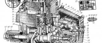
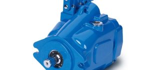
A radial piston pump is a positive displacement pump, in the design of which the axis of the drive shaft is perpendicular to the axes of movement of the working pistons or the angle between them is at least 45°. Mechanisms whose angle is less than 45° are classified as axial type.
Radial piston pumps
A radial piston pump is often called a radial plunger pump .
I use such pumps in hydraulic systems with high pressure. Most often they are used in installations with pressures up to 32 MPa; there are also units operating at higher pressures and reaching values of 100 MPa. Radial piston type units are limited in shaft rotation speed to 1500 rpm. This is due to the high inertia of the rotating parts.
Device
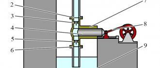
There are two types of design of such hydraulic systems:
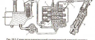
Diagram of radial piston pumps
- Hydraulic pump with eccentric rotor. On the diagram under the letter A
- Hydraulic pump with eccentric shaft. On the diagram under the letter B
Device with eccentric rotor
The main part is the rotor with pistons built into it. There can be many pistons and they can be located in several rows. The rotor rotates in a housing (Stator). The rotor axis is installed with a center offset relative to the stator axis by the value “e” as shown in the figure. The intake and discharge systems are located in the center and are separated from each other by a special jumper.
Eccentric shaft device
In this hydraulic system device, the pistons are located in the pump stator. The axis of the stator and the shaft coincide, but there is a special kind of cam on the shaft, offset relative to the stator by a distance “e”. Such hydraulic installations have valve distribution. When the working chamber is compressed, the suction valve closes and the discharge valve opens. When the working chamber expands, the opposite situation occurs.
Impeller diameter correction
Obviously, the impeller diameter cannot be reduced while the pump is running. Compared to the throttle and bypass control methods, which can be carried out while the pump is running, correction of the impeller diameter must be carried out before installing the pump or during repair work. The following formulas show the relationship between impeller diameter and pump parameters:
Note that these formulas reflect the operation of an ideal pump. In practice, reducing the diameter of the impeller leads to a decrease in the efficiency of the pump, i.e. to reduce its efficiency. With a slight correction of the diameter DH2 > 0.8 • DH1, the efficiency will decrease by only a few percent. The level of efficiency reduction depends on the type of pump and its operating point.
As can be seen from the formulas, the ratios of changes in flow and pressure are equal to each other and equal to the square of the ratio of the impeller diameters. In this case, the working points are located on a straight line originating in the coordinate system at the point (0, 0). The ratio of power consumption before and after correction is equal to the ratio of diameters to the fourth power.
Principle of operation
Operating principle of a radial piston pump
The rotor rotates in the stator (housing) together with the pistons; the pistons slide along the housing, pressing tightly against it due to springs. As a result of rotation of the rotor, the pistons perform reciprocating movements. The pistons move in a circle and switch between two phases:
- Absorption phase. The piston extends, the working chamber increases, the discharge valve closes and the suction valve opens, it is connected to the liquid intake hole. The piston moves in a circle until it extends to its maximum point.
- Pressure phase. The piston switches to the discharge port and begins to move in, the suction valve closes and the discharge valve opens, the working chamber decreases, as a result of which pressure is created and the liquid is forced out of the pump. The piston remains in this phase until the maximum compression point of the working chamber, and then switches to the suction phase.
A radial piston pump can have two or more multiple actions. This means that one plunger makes several working strokes during one rotation of the rotor. This effect is achieved through a special change in the surface of the stator.
List of GOST standards used in industrial hydraulics
GOST 12445-80 “Hydraulic volumetric drives, pneumatic drives and lubrication systems. Nominal pressures."
GOST 13823-78 “Volume hydraulic drives. Volumetric pumps and hydraulic motors. General technical requirements."
GOST 14057-68 “Gear pumps. Rows of basic parameters.”
GOST 14058-68 “Slider pumps. Rows of basic parameters.”
GOST 14059-68 “Piston pumps. Rows of basic parameters.”
GOST 14060-68 “Gear hydraulic motors. Rows of basic parameters.”
GOST 14061-68 “Gate hydraulic motors. Rows of basic parameters.”
GOST 14062-68 “Piston hydraulic motors. Rows of basic parameters.”
GOST 14063-68 “Hydraulic and pneumatic equipment. Rows of basic parameters."
GOST 14064-68 “Hydraulic accumulators. Rows of basic parameters.”
GOST 14658-86 “Displacement pumps with hydraulic drives.
Acceptance rules and test methods." GOST 15108-80 “Displacement hydraulic drives, pneumatic drives and lubrication systems.
Labeling, packaging, transportation and storage" (with Amendments No. 1, 2, 3) Resolution of the USSR State Standard of November 28, 1980 N 5588 GOST of November 28, 1980 N 15108-80 GOST 16514-96 "Volume hydraulic drives. Hydraulic cylinders. General technical requirements" Resolution of the State Standard of Russia dated 02.02.2001 N 54-st GOST dated 02.02.2001 N 16514-96
GOST 16517-82 “Hydraulic equipment. General technical requirements."
GOST 16769-84 “Hydraulic accumulators. General technical requirements."
GOST 17069-71 “Hydrodynamic transmissions. Bench test methods."
GOST 17216-2001 “Industrial cleanliness. Liquid purity classes."
GOST 17411-91 “Volume hydraulic drives. General technical requirements."
GOST 17752-81 (ST SEV 2455-80) “Volume hydraulic drive and pneumatic drive. Terms and definitions" (with Amendments No. 1, 2) Resolution of the USSR State Standard of December 31, 1981 N 5818 GOST of December 31, 1981 N 17752-81
GOST 18464-87 “Hydraulic cylinders. Acceptance rules and test methods."
GOST 18464-96 “Volume hydraulic drives. Hydraulic cylinders. Acceptance rules and test methods."
GOST 19749-84 “Fixed detachable connections of pneumatic hydraulic systems. The shutters are closed. Types and technical requirements."
GOST 20245-74 “Hydraulic equipment. Acceptance rules and test methods."
GOST 20719-83 “Hydraulic motors. Acceptance rules and test methods."
GOST 21329-75 “Slot filters for pressure up to 6.3 MPa (approximately 63 kgf/cm2). Technical conditions."
GOST 21976-76 “Hydraulic throttling valves with a flat rotary spool. Basic dimensions."
GOST 22976-78 “Hydraulic drives, pneumatic drives and lubrication systems. Acceptance rules."
GOST 24242-97 “Volume hydraulic drives. Designations of letter holes of hydraulic devices, mounting plates, control devices and electromagnets.”
GOST 24679-81 “Four-line spool valves at Rnom up to 32 MPa. Technical conditions."
GOST 25020-84 “Hydraulic and pneumatic cylinders. Connecting threads of rods and plungers."
GOST 25277-82 “Filter elements for volumetric hydraulic drives and lubrication systems. Acceptance rules and test methods."
GOST 25476-82 “Hydraulic drives and lubrication systems. Filters. Acceptance rules and test methods."
GOST 25553-82 “Single-stage hydraulic cylinders for a nominal pressure of 16 MPa (160 kgf/cm2). Connecting threads of rods and plungers."
GOST 26058-85 “Industrial robots. Hydraulic motors of actuators. Types, main parameters and connecting dimensions."
GOST 26496-85 “Hydraulic accumulators. Acceptance rules and test methods."
GOST 26650-85 “Single-stage hydraulic cylinders for a pressure of 16 MPa. Connecting dimensions."
GOST 26890-86 “Hydraulic equipment. Connecting dimensions of the joint planes of the mounting plates.”
GOST 2.782-96 ESKD “Conventional graphic symbols. Hydraulic and pneumatic machines" Resolution of the State Standard of Russia dated 10/04/1996 N 10 GOST dated 10/04/1996 N 2.782-96
GOST 27851-88 “Displacement pumps for hydraulic drives. Method of accelerated comparative tests for life."
GOST 28160-89 “Marine, diesel and industrial diesel engines. Pumps for cooling systems. Feed calculation method."
GOST 28413-89 “Displacement pumps and hydraulic motors for hydraulic drives. Methods of accelerated tests for failure-free operation."
GOST 28761-90 “Volume hydraulic drives. Rotary hydraulic motors. General technical requirements."
GOST 28971-91 “Volume hydraulic drive. Servo devices. Test methods."
GOST 29015-91 “Volume hydraulic drives. General test methods."
GOST 30362.1-96 “Volume hydraulic drives. Hydraulic cylinders with a one-sided rod for a nominal pressure of 25 MPa. Connecting dimensions."
GOST 30362.2-96 “Volume hydraulic drives. Hydraulic cylinders with a one-sided rod for a nominal pressure of 25 MPa. Connecting dimensions of holes for liquid supply."
GOST 30481-97 “Volume hydraulic drives. Throttle hydraulic distributors with servo regulation, four- and five-line. Connecting dimensions of the joint planes of the mounting plates.”
GOST 30526-97 “Volume hydraulic drives. General test methods."
GOST 31247-2004 “Industrial cleanliness. Determination of contamination of a liquid sample using automatic particle counters" Order of Rostekhregulirovaniya dated 02/16/2005 N 24-st GOST dated 02/16/2005 N 31247-2004
GOST 4.37-90 SPKP “Displacement hydraulic drives, pneumatic drives and lubrication systems. Nomenclature of indicators" Resolution of the USSR State Standard of 05/11/1990 N 1168 GOST of 05/11/1990 N 4.37-90
GOST R 50556-93 “Volume hydraulic drive. Particle contamination analysis. Sampling of liquids from pipelines of operating systems.”
GOST R 50557-93 “Volume hydraulic drive. Vessels for liquid samples. Evaluation and control of cleaning methods."
GOST R 52543-2006 (EN 982:1996) “Volume hydraulic drives. Safety requirements" Order of Rostekhregulirovaniya dated May 10, 2006 N 88-st GOST R dated May 10, 2006 N 52543-2006
Performance calculation
Q = hSna = 2eSna
Q – pump performance;
e – eccentricity, displacement relative to the axis of rotation of the shaft in the figures above was also designated as “e”;
L – stroke of the plunger in the cylinder, in the standard situation L=2*e;
S – plunger area;
a – number of plungers in the block;
n – block rotation speed;
Performance in adjustable pumps is regulated by changing the deviation of the “e” axis.
Proportional pressure control (indirect)
The main function of the system presented in Fig. 4.2.4 is to maintain a constant pressure drop across control valves installed, for example, on radiators.
As discussed in Chapter 3, pressure loss in a system is directly proportional to the square of the flow rate. The best way to regulate the pump in such a system is as shown in the figure to the right, where the pump maintains a constant pressure drop.
When the required flow rate in the system is small enough, the pressure losses in the pipeline, heat exchanger, fittings, etc. are also small, and the pump only compensates for the pressure losses at the control valve, Nst - Ntr. When the required flow rate increases, the pressure loss increases quadratically and, therefore, it is necessary to increase the pump pressure (Fig. 4.2.4, blue curve).
Such a system can be installed in two ways:
- The differential pressure sensor is located on the pump - DPT1, see fig. 4.2.4.
- The differential pressure sensor is located on consumers - DPT2, fig. 4.2.4.
The advantage of the first solution is that the pump, PI controller, frequency converter and sensor are located close to each other, which makes installation of the system easier. With this installation, the control system and pump are a single unit, see section 4.4. To enable this system and ensure its operation, the required differential pressure value must be entered into the pump control system. This data will be used to calculate the flow rate and also to calculate by how much the set value Nust must be reduced at a given flow rate to ensure that the pump operating parameters correspond to the system characteristics shown in Fig. 4.2.4 in blue.
The second installation option, when the flow sensor is installed on radiators, will cost more, because In this case, the cable must be laid. The parameters of this system are approximately the same as those of the first one. The sensor measures the pressure drop at the consumption site, and the system automatically changes its parameters to compensate for the pressure drop in the supply pipeline, etc.
Advantages and disadvantages of radial piston pumps
Positive sides:
- Produce high pressure in the hydraulic system;
- There are models with the option of adjusting the working volume of the feed;
- The efficiency is at a fairly high level at high pressure;
- High energy intensity per unit mass;
Negative sides:
- Complex device, low reliability;
- The need for specific processing of parts, as well as the complex structure of the pump itself, leads to a high price for these units;
- Fine filtration of the working fluid is required;
- High supply and flow pulsation;
- Take up a lot of space;
- Low main shaft torque;
Bypass regulation
The valve of the bypass (bypass) pipeline is installed in parallel with the pump and is used to regulate its parameters, see fig. 4.1.3.
Compared to a conventional valve installed downstream of the pump, bypassing will ensure a certain minimum flow rate Qbp of the pump, regardless of the characteristics of the system. The pump flow QН is equal to the sum of the system flow QС and the flow through the bypass pipeline Qbp.
The bypass valve will provide the maximum permissible pressure in the Nmax system, see fig. 4.1.3. Even if the required flow rate in the system is zero, the pump will never operate on a closed valve. As with throttling control, the required flow rate of the QC system can be achieved with a smaller pump and without bypass; As a result, the flow through the pump will be lower and, therefore, the energy consumption will also be reduced.
Advantages of pumps with built-in frequency converter
The use of pumps with a built-in frequency converter is the optimal solution in many industrial sectors. And the main reason for this is to combine the advantages of a variable pump with the advantages obtained from combining a pump, a frequency converter, a PI controller and sometimes also a pressure sensor into a single unit, see fig. 4.4.1.
A pump with a built-in frequency converter can easily be called a system capable of solving various problems while saving energy. When it comes to interchangeability, pumps with built-in frequency converters are ideal as they can be installed in place of fixed pumps at no extra cost. To carry out such work, it is necessary to equip the pump with a built-in frequency converter, after which it is ready for operation. The installer only needs to set the set value (pressure), and the system is ready for operation.
What follows is a brief description of the advantages offered by pumps with a built-in frequency converter.
Ease of installation
Pumps with a built-in frequency converter are just as easy to install as unregulated pumps. Preliminary settings and adjustments of the pump are made at the manufacturer.
Energy optimization
Since the pump, motor and frequency converter are completely compatible with each other, the operation of such a system significantly reduces energy consumption.
Single supplier
A single supplier can provide a pump, a frequency converter and a sensor, which naturally makes it easier to determine the dimensions of the installation, select it, order it, as well as service and repair.
Wide range of operating parameters
Pumps with integrated frequency converter have a very wide range of operating parameters, which allows them to operate with great efficiency under different operating conditions and meet a wide range of requirements. Therefore, when replacing fixed pumps with a narrow operating range, you will need fewer variable pumps.