The front axle on the UAZ does not turn on
Although the UAZ SUV has two drive axles, unlike, for example, the all-wheel drive Niva, it does not have a center differential in its transmission. And the front drive axle is intended only to overcome difficult sections of the road or off-road. Moreover, in order to put the front axle into operation, you first need to turn the hub quick-clutch (hub) on the hubs of each front wheel by hand to the 4x4 position (on old UAZs, they are turned with a special key) and only then the low or high gear is engaged transfer case.
Inexperienced UAZ drivers, who have skidded for the first time in their car, in order to get out, engage the front axle, but the axle refuses to become the drive axle. They think that there is some kind of malfunction in it and they need to find it. But later it turns out that they did not know that the hubs had to be turned on before overcoming a section of the road on which it is possible to stall. Since after they are turned to the 4x4 position, the front drive axle will turn on only after the front wheels make at least 1-1.5 revolutions without slipping.
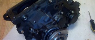
If the front drive axle of a UAZ refuses to work, simple diagnostics are performed to identify the unit in which the fault has appeared. They turn on the hubs of both front wheels, hang up the front axle and try to turn the cardan going from the front axle to the transfer case. If the front wheels rotate, then you will have to remove the transfer case and look for a fault in it, and if the wheels do not rotate, then the fault is in the front axle.
The most likely malfunction in the front axle will be the failure of the hub, which has worn out or cut off small sharp splines. With the help of these splines, when the hub is turned on, the coupling body engages with the inner bushing, which is mounted on the axle shaft. And if the splines are cut, then rotation from the axle shaft will not be transmitted to the wheel hub.
The front axle will not work if there is a malfunction: in the gear shift mechanism of the transfer case; the downshift and upshift fork was deformed; The transfer case gear teeth are worn out. Sometimes the front axle disengages spontaneously. This may be caused by wear of the transfer case shaft bearings, resulting in misalignment of the shafts. Wear of the latch parts or breakage of the spring in the transfer case activation mechanism will also lead to spontaneous shutdown of the front axle.
Source
12 ..
CONTROLS OF THE UAZ-469 CAR
The location of the vehicle controls is shown in Fig. 6.
Steering wheel 1 is located on the left side. In the center of the steering wheel there is a horn button 2. On the right side of the steering column there is a switch handle 3
direction indicators. The handle automatically returns to the neutral position when the steering wheel is turned in the opposite direction (the vehicle is moving in a straight line). An internal rear view mirror 4 is installed on the central pillar of the wind frame.
An electric windshield wiper 5 is installed in the upper part of the wind frame. To the right of the driver is a panel 6
devices. There are two sun visors 7 on the wind frame. To clean the windshield, two windshield wiper blades 8 are installed. And in the lower part of the wind frame there are two pipes 9 for blowing the windshield. The wind frame has two locks 10.
Rice. 6. Controls (for names of positions, see text)
Rice. 7. Diagram of the positions of the gearbox lever and transfer case levers
To the right of the driver on the front panel there is a handrail// passenger. There is also a lantern 12 under it. To the right of the driver, under the front panel, there is a handle 13 for the ventilation and heating hatch. The hatch damper is opened by pulling the handle towards you. The heater has adjustable dampers 14 for supplying warm air to the feet of the driver and passenger. To the right of the driver is the lever 15 for engaging the front drive axle. The front drive axle is engaged when the lever is in the forward position. There is a cover 16 on the heater in the middle part; it allows warm air to enter the passenger compartment. The transfer case control lever 17 is also located there, which can occupy three positions: forward position (along the vehicle) - direct transmission is engaged: middle position - neutral; rear position - downshift is engaged. Next to the driver there is a gear shift lever 18, on the handle of which there is a gear shift diagram. The diagram of the positions of the gearbox and transfer case levers is shown in Fig. 7. To the left of the gear lever is the parking brake lever 19. Under the front panel to the right of the driver there is a handle 20 for the body ventilation and heating hatch. On the floor there is a handle 21 for switching fuel tanks, which can occupy three positions: the handle is turned forward - the valve is closed; the handle is turned to the left - the left fuel tank is on, the handle is turned to the right - the right fuel tank is on.
On the floor of the body under the driver’s right foot there is a throttle control pedal 22.
On the floor of the body in front of the driver's seat there is a hatch cover 23 for access to the filler plug of the brake master cylinder. Under the driver’s feet there are pedals 24, 25, brakes and clutches. To the left of the driver in the floor of the body there is a foot switch 26 lights. By pressing the button with the headlights on, you can switch to low or high beam. To the left of the driver on the side of the body there is a handle 21 for controlling the radiator shutters. The blinds close when the handle is pulled towards you. An external rear view mirror 29 is installed on the left side of the body. On the front inclined floor of the body at the top there is a battery ground switch 30 (has two buttons). When you press the button head, the switch connects the battery to ground. To disconnect the battery from ground, press the bracket located on the side. To the left of the power switch on the side there is a plug socket 28 for a portable lamp.
CONTROL AND MEASURING INSTRUMENTS FOR UAZ-469 CARS
On the instrument panel (Fig. there is a speedometer 17, which shows the speed of the car in km/h, and a counter installed in it shows the total mileage of the car in km. The speedometer scale has a hole for a warning lamp (with a blue lens) for the high beam headlights. Ammeter 2, used to determine the strength of the charging (the arrow deviates to the right, towards the + sign) or discharge (the arrow deviates to the left, towards the - sign) current of the battery.
Rice. 8, Instrument panel (for names of positions, see text)
Turning headlight switch 3 is installed on UAZ-469 and UAZ-469BG vehicles, and when there is no switch, a plug is inserted into the hole. Oil pressure indicator 4 shows the pressure in the engine lubrication system in kgf/cm2. Indicator lamp 5 for emergency oil pressure drop with a red lens. The warning light comes on when the ignition is turned on and goes out after the engine starts running. A short flashing of the lamp when the engine speed decreases does not indicate a malfunction of the lubrication system, if the lamp immediately goes out when the engine speed increases. The indicator lamp 6 of the turn indicators with a green lens lights up when the turn indicators are turned on. Coolant temperature indicator 7 shows the temperature of the liquid in the cylinder block when the ignition is on. The sensor for this indicator is located in the water pump bracket. Indicator lamp 8 for emergency overheating of the coolant with a red lens lights up when the liquid temperature is above 106 ... 109 ° C. The sensor is located in the upper radiator tank. The 9th fuel level indicator has a scale with 0 divisions; 0.5; P, corresponding to the empty, half and full capacity of the tank. The fuel level indicator is equipped with two sensors, according to the number of tanks, and shows the amount of fuel in each tank separately. To turn on the right or left tank sensor, there is a switch 12 on the instrument panel, which has two positions: down - the right tank sensor turns on; up - left tank sensor. The indicator is only valid when the ignition is on. Switch 10 of the body light. Handle 11 is used to manually control the carburetor throttle; When the handle is pulled out, the damper opens. The position of the handle can be fixed by rotating it 90° around its axis. The handle must be recessed while the vehicle is moving. The combined ignition and starter switch 13 (lock) (Fig. 9) has three positions: middle - off, first right - ignition on;
second (far right) - ignition and starter are on; third left - the receiver is turned on (when it is installed). Handle 14 (Fig. of the central light switch is used to turn on the headlights, headlights, rear lights and instrument lighting lamps. The switch handle has three fixed positions: the first - everything is off; the second - the front lights are on (or low beam headlights depending on the position of the foot light switch), rear lights and instrument lighting; third, low or high beam headlights are turned on depending on the position of the foot light switch, rear lights and instrument lighting. By turning the switch knob, the intensity of instrument lighting is adjusted.
Switch 15 of the body heater electric motor can be set to three positions: by moving the switch handle up, an increased speed of rotation of the electric motor shaft is turned on, by moving the handle down, a reduced speed of rotation of the electric motor shaft is turned on, and with the handle in the middle position, the electric motor is turned off.
Handle 16 is used to manually control the carburetor air damper; by pulling the handle, you can partially or completely close the air damper - the working mixture is enriched. After the engine warms up, the handle should be recessed. The position of the handle can be fixed by rotating it around its axis by 90°. Switch 1 is designed to control the operation of the windshield wiper and washer; turning clockwise turns on the wiper, and pressing the handle in the axis direction turns on the washer. Button 18 thermal fuse in the lighting circuit. 19 — alarm switch. To turn on, pull the handle towards you.
Using a transfer case
general information
The transfer case is designed to distribute torque between the front and rear axles of the car.
The transfer case mode switch lever is located in the lower part of the center console, behind the gear shift lever (Manual transmission)/selector lever (AT). On models with manual transmission, the lever allows you to select one of four transmission modes: 2H, 4H, (N) and 4L, on models with AT - one of three: 2H, 4H, and 4L.
On models equipped with vacuum freewheels, switching between 2H and 4H modes can be done directly while the vehicle is moving at low speed (up to 40 km/h), and there is no need to depress the clutch on models with manual transmission.
To activate the 4L mode, you must completely stop driving, depress the foot/parking brake, depress the clutch (models with manual transmission)/move the selector lever to the “N” position (models with AT), then carefully shift the transfer case lever to position 4L (models with AT )/first to position N, then to position 4L (models with manual transmission).
Assignment of transfer case mode switching lever positions
N
— Only on models with manual transmission.
In the neutral position of the transfer case, the drive of both axles is disabled. The indicator light built into the instrument cluster (see Section Instrument cluster, meters, warning lamps and indicator lights
) is also turned off.
2H
— Transfer case main mode. The drive is carried out only on the wheels of the rear axle. The indicator light is off.
4H
— The drive is carried out on the wheels of both axles. The indicator light is on. The mode is intended for driving on roads with slippery or loose surfaces (snow, mud, sand), as well as when the wheels lose traction while driving in 2H mode.
4L
— All four wheels are driven, the transfer case gearbox is switched to a downshift. The indicator light is on. Maximum wheel grip and maximum traction force are ensured. It is recommended to navigate through areas covered in deep snow/mud/sand, particularly steep inclines/descents, and when towing heavily loaded trailers. The mode is not intended for long-term use.
Although the UAZ SUV has two drive axles, unlike, for example, the all-wheel drive Niva, it does not have a center differential in its transmission. And the front drive axle is intended only to overcome difficult sections of the road or off-road. Moreover, in order to put the front axle into operation, you first need to turn the hub quick-clutch (hub) on the hubs of each front wheel by hand to the 4x4 position (on old UAZs, they are turned with a special key) and only then the low or high gear is engaged transfer case.
Inexperienced UAZ drivers, who have skidded for the first time in their car, in order to get out, engage the front axle, but the axle refuses to become the drive axle. They think that there is some kind of malfunction in it and they need to find it. But later it turns out that they did not know that the hubs had to be turned on before overcoming a section of the road on which it is possible to stall. Since after they are turned to the 4x4 position, the front drive axle will turn on only after the front wheels make at least 1-1.5 revolutions without slipping.
If the front drive axle of a UAZ refuses to work, simple diagnostics are performed to identify the unit in which the fault has appeared. They turn on the hubs of both front wheels, hang up the front axle and try to turn the cardan going from the front axle to the transfer case. If the front wheels rotate, then you will have to remove the transfer case and look for a fault in it, and if the wheels do not rotate, then the fault is in the front axle.
The most likely malfunction in the front axle will be the failure of the hub, which has worn out or cut off small sharp splines. With the help of these splines, when the hub is turned on, the coupling body engages with the inner bushing, which is mounted on the axle shaft. And if the splines are cut, then rotation from the axle shaft will not be transmitted to the wheel hub.
The front axle will not work if there is a malfunction: in the gear shift mechanism of the transfer case; the downshift and upshift fork was deformed; The transfer case gear teeth are worn out. Sometimes the front axle disengages spontaneously. This may be caused by wear of the transfer case shaft bearings, resulting in misalignment of the shafts. Wear of the latch parts or breakage of the spring in the transfer case activation mechanism will also lead to spontaneous shutdown of the front axle.
UAZ loaf does not turn on front axle reason
| Page 1 of 3 | 1 | 2 | 3 | > |
The front axle does not work. Today I tried to drive up a hill with the hubs and front end turned on, but it was clear in the snow that only the rear wheel was slipping. The turning radius has increased, the steering wheel gets knocked out of your hands if I try to take it sharper. What is the reason?
P.S. Front-wheel drive cars go up hills, but I don’t (shame).
Did you turn on the bridge with a lever in the cockpit?
climb into the sub-vehicle by first turning on the bridge in the cabin, tightening the hubs and turning the cardan shaft by hand. If you did it, then see that either the mechanism for switching on the bridge on the RC or the hubs or one hub is not working.
Source
How to turn on the front axle on a UAZ
Engaging the front gear may be necessary if it is necessary to turn from an asphalt road surface onto a country road or terrain with potholes and mud. In the new conditions, rear-wheel drive will not cope with difficulties. Engaged front-wheel drive is a means of solving the problem.
System startup sequence:
- Stop the car and check the operation of the front wheel quick release clutch. It is turned on by turning the wheels clockwise until they stop.
- Move the rightmost lever forward to switch the front wheels to driving status. Now their rotation will be equivalent to the rear.
If the road condition worsens while driving, it becomes more and more difficult to continue driving, the engine stalls, you need to stop the vehicle and engage a lower gear. To do this, you will need to move the middle lever back. In low gear, all 4 speeds are available, and driving becomes easy and smooth again.
After overcoming off-road conditions, it is immediately better to put the middle lever in its original position and move the transfer gearbox to a higher level. On the highway, it is recommended to stop the front-wheel drive and quick-release clutches to save 2 liters of fuel. The measures help reduce noise levels while driving.
How the UAZ front axle works
The diagram of the UAZ loaf front axle allows us to determine that it consists of several components:
Below is the structure of the components of the front axle of the UAZ loaf car.
Carter
The UAZ loaf axle housing consists of 2 parts. The parts are bolted together to form a gearbox housing. Parts of the crankcase are equipped with fastenings for installing springs and shock absorbers.
IMPORTANT: As the vehicle is used, the lubricant in the crankcase heats up and expands. At the same time, the pressure in the crankcase cavity increases. To prevent leakage of the axle housing, a breathing valve is provided. It is installed on the axle housing of the UAZ front axle and is necessary to communicate the crankcase cavity with the atmosphere.
There are turning mechanisms along the edges of the bridge. They are necessary to drive a car. The mechanisms are pivotally connected to the edges of the crankcase casing. Trunnions are installed on the rotating mechanisms. They are necessary for articulated connection with the vehicle hubs. To reduce the degree of friction, the hub is mounted on roller bearings.
Gearbox
The UAZ loaf front axle gearbox consists of a main gear and a cross-axle differential. When the front axle of the UAZ loaf is turned on, the torque from the gearbox is supplied through the driveshaft to the gearbox flange. It is mounted on the same shaft with the main gear drive gear.
As the drive gear rotates, it transmits torque to the driven gear. Compared to the drive gear, it has a large diameter. This allows you to reduce the torque transmitted from the transfer case.
REFERENCE: The teeth of the gears of the main gear of the UAZ vehicle gearbox are located at an angle. This prevents the gear teeth from hitting each other, thereby reducing the noise level when the vehicle is moving.
An interwheel differential is located inside the driven gear. It consists of conical satellites and their axes. The differential mechanism includes axle shaft splines. The differential allows, when turning a car, to achieve a difference in the speed of rotation of the wheels of one axle. You can also read about UAZ 390945.
Half shafts
The front axle of the UAZ loaf car is a shaft with splines on the edges. On the one hand, the splines are installed in the differential gearbox. The second side of the axle shaft drives the wheel hub. The transmission of torque from the front axle gearbox to the wheel mechanism is carried out using a CV joint. It allows you to transmit torque regardless of the angle of rotation of the wheel mechanisms.
A distinctive feature of the front axle of the UAZ Bukhanka is the ability to disconnect the wheel hubs from the axle shafts. This is necessary to prevent wear of the rotating parts of the gearbox during prolonged movement on good quality surfaces.
Possible bridge malfunctions and their causes
The front axle of the UAZ loaf car is distinguished by its reliability and unpretentiousness to operating conditions. The most common malfunctions are:
- Crankcase seal failure. Excess pressure that occurs when the oil heats up while the car is moving causes the crankcase to fail to seal. To prevent malfunction, it is necessary to regularly check the functionality of the breathing valve;
- Bearings are worn out. Occurs as a result of improper operation of the front axle of a UAZ loaf car. Switching the UAZ loaf front axle to the on position when driving on a good quality surface leads to rapid wear of the gearbox bearings. To prevent bearing damage, it is necessary to connect the front axle only for off-road driving;
- Increased wear of rotating parts. Occurs due to poor quality lubricant. It is necessary to change the oil in the front axle regularly. The cause of the malfunction may be water entering the gearbox housing when fording. To prevent water from entering the gearbox housing, the breathing valve is equipped with a hose attached under the engine compartment cover.
- Malfunction of the cross-axle differential. Often occurs due to wear on the pins. To prevent damage, it is necessary to regularly inspect the pin mechanism for play. If the permissible values are exceeded, the kingpins should be replaced;
- Breakage of the main gear drive shaft bearing. Occurs due to a malfunction of the driveshaft crosspiece. It is necessary to regularly check the integrity of the crosspiece.
- High degree of wear of conical satellites or their axes. The integrity of the conical satellites and their axles is affected by the difference in pressure in the tires of the front axle wheels. To avoid damage, it is necessary to constantly monitor tire pressure.
What is the front axle switch and where is it located?
The front axle switch is a device that controls the engagement of all-wheel drive, which gives a signal to connect the front axle differential.
The front axle switch is usually located on the dashboard. When you turn it on, all-wheel drive mode is activated. This arrangement is used in the case of electronically controlled all-wheel drive, as opposed to mechanical all-wheel drive, which is activated by a lever similar to a gear shift located on the floor of the car.
Some drivers prefer a manual system because automatic engagement can be delayed. If the electronic drive does not engage, the reason may be a faulty front axle switch.
Repair of the most common faults
Restoring the bridge to operability is not very difficult: but it is required to be careful when performing operations. What “diseases” are most common?
Leak formation
Where the steering knuckle connects to the bridge, there is an oil seal - one of the weak points of the design in terms of lubricant leakage. The oil seal can leak oil not only due to wear, but also when the breather is clogged. If you add more lubricant than required, the result will be the same: a leak. There are two types of oil seals:
- rubber: inexpensive, but also short-lived;
- polyurethane: more expensive, have a long service life.
To replace a part, place the car on a level place and jack up the problem side, loosening the wheel nuts in advance. Further:
- remove the steering knuckle;
- clamp the part in a vice;
- pull out the oil seal by prying it with a flat screwdriver or other suitable tool;
- pull the oil seal out of the support cavity;
- Lubricate the seal before installation;
- press in the oil seal using a tube of the appropriate diameter.
- Installation is in the reverse order.
The most problematic place of the bridge
The mechanism began to hum
First of all, check the oil level. If it is normal, the bridge will have to be removed and disassembled. If the bridge hums constantly in any driving mode, the reasons may be as follows:
- incorrect setting or limiting service life of differential bearings;
- breakage (wear) of the axle shaft (its bearing);
- wear, damage, incorrect gear adjustment.
These bearings simply need to be replaced with new ones. If a humming noise appears during a sudden stop or acceleration, the reasons are as follows:
- incorrect clearance between the final drive gears;
- The final drive gear teeth do not mesh correctly.
In this case, you need to correctly adjust the gearing or replace defective parts. If the bridge hums when the UAZ enters a turn and moves in a straight line, the reasons may be the following:
- satellites rotate with great effort;
- abnormal operation of the axle gears in the differential;
- destruction, severe wear of the axle bearing;
- incorrect clearance between gears located in the differential.
To restore the functionality of the mechanism, adjust the clearances correctly and replace damaged, worn bearings. It is worth noting that the desired result when adjusting the gaps can only be achieved on a bench.
Wheel axial play
It occurs when the wheel bearings are incorrectly adjusted or when they completely fail, which is caused by over-tightening. As a result, the bearings become very hot, the smear liquefies and flows out. Algorithm of actions when performing the correct adjustment:
- Jack up the wheel on the desired side;
- Use a puller to remove the axle shaft;
- Move the lock washer to the side and unscrew the lock nut;
- Spin the wheel: if it rotates tightly, the reason may lie in jamming of the cuffs, contact of the drum and pads, etc.;
- Tighten the adjusting nut. Do this gradually while spinning the wheel. Use the WRENCH;
- Unscrew the nut about a third of a turn and install the lock washer. Tighten the nut and lock it;
- Check how the wheel rotates: it should spin freely without sticking;
- Replace the axle shaft, replace the bolts and tighten them.
You can finally check while moving. If the hub gets very hot, loosen the hub nut about 1/6 of a turn.
Malfunctions and repair work
Common malfunctions of the UAZ front axle and possible repairs:
- Leakage of lubricating fluids. Check the tubes and connecting elements for mechanical damage - the cuffs and flange for functionality, the oil container for the optimal fluid level.
- High wear of fasteners.
- Bearing defects caused by the use of poor quality material by the car plant.
- Broken axle teeth. Adjustment will not help; parts need to be replaced.
- Mechanical defects of the beam.
- Wear of elements. The situation is resolved by replacing it with new spare parts.
- Poor grip of the bearings and main gears indicates the need for tension adjustment.
Bridge repairs begin after diagnosing and searching for the cause of problems in the functioning of the mechanism, which are diverse:
- transmission components of a rear-wheel drive vehicle are faulty due to regular movement over difficult terrain;
- use of consumables and lubricants of unsuitable quality;
- Failure to monitor tire pressure can lead to shaft and bearing failures.
Most often, car owners are faced with a violation of the axial space of the kingpins and are knocked out of the required position. To diagnose, you need to jack up the front of the vehicle and move the wheel in a vertical plane. The presence of axial play indicates the need to adjust the clearance of the pins.
How to adjust bridges
You can adjust the UAZ axles yourself. This will require a number of tools and good knowledge of the mechanism. Access to the necessary parts and assemblies is possible after dismantling the structure and separating the crankcase parts. The first sign of the need to adjust the gearbox is loud noise and malfunctions of the part. Such work is required after diagnosing the condition of bridges. Adjustment includes a number of activities.
At the first stages of repair work, ensure that the nuts of the brake elements can be loosened freely. The tools you will need are a split wrench, brake fluid and a mixture of WD-40. The bridge is dismantled as follows:
- remove the fasteners between the drive gear flange and the propeller shaft;
- secure the shaft to the side;
- place the front part of the vehicle on jacks, raising the wheels above the surface;
- additionally install safety supports;
- remove the nut between the brake pipe and hose and close the hole with a plug to avoid large losses of fluid;
- after removing the lower fasteners and moving the shock absorbers from the axle, the bridge will lower;
- remove the stepladder nuts and roll out the bridge (without wheels it weighs more than 100 kg).
For adjustment and repair work, you will again need a split wrench, a metal corner with pins, a universal puller, a container with brake fluid, transmission oil (if you don’t want to fill in the old one), a set of bearing spacers for adjusting the driven gear and a micrometer. Preparatory work:
- remove 10 bolts connecting the axle shafts to the hubs;
- remove the axle shaft from the crankcase;
- Unscrew the fasteners of the brake pipes;
- remove the tee from the bracket;
- remove the connecting elements between the crankcase parts, keeping the gasket;
- Remove the differential housing and driven gear, outer rings.
The main support of the drive gear, which determines the reliability of the bridge, is a tapered roller bearing located in the front part, consisting of 2 rows. A similar part on the opposite side performs an auxiliary function. To repair, you will need to remove the right drive gear by removing the bolts.
All disassembled components should be inspected for wear and replaced if necessary. The shims are located in the middle of the inner rings of the bearing. Their thickness is measured with a micrometer, the part with the smallest value is removed to create preload in the bearing. Adjust the part until the dynamometer shows a resistance of no more than 3.5 kgf. Otherwise, you will need to remove another gasket. Tight turning indicates the need to increase the thickness of the gasket pack. After determining the desired value, you can put the unit back together.
The next step is to adjust the differential bearings:
- press in the outer and inner rings;
- mount the differential with the main gear into the crankcase;
- install the gasket;
- separate the crankcase parts;
- remove the differential, check the clearance of the differential and bearing rings;
- install the main gear mechanism on the right side of the crankcase;
- install the drive shaft;
- pull together the crankcase halves, observing the required gap size, adjusting it if necessary with cardboard spacers.
Connection diagram for the front axle UAZ loaf
Some car owners are wondering how the front axle on a UAZ loaf is engaged? The front axle is engaged in two ways:
- A lever installed in the cab. The lever controls the transfer case. When the front axle of the UAZ loaf is turned on using a lever installed in the cabin, torque from the transfer case is transmitted along the driveshaft to the drive axle.
- Using couplings installed in wheel mechanisms. It is possible to disconnect the drive axle hub from the axle shaft. Switching the UAZ Bukhanka front axle on and off using clutches allows you to reduce the load on the gearbox when driving on hard surfaces.
IMPORTANT: after disconnecting the clutches located in the wheel mechanisms, connecting all-wheel drive using a lever from the passenger compartment will be impossible.
To engage the clutch, it is necessary to remove the protective cover of the drive axle hub. Using a hexagon, screw the coupling cap until it stops. The axle shaft splines will engage and the hub will be connected to the gearbox. To disengage the clutch, perform the procedure in reverse order.
To connect all-wheel drive using a lever installed in the passenger compartment, it is necessary to do the following:
- Disengage the clutch;
- Set the gearshift lever to neutral position;
- Move the control lever to the extreme forward position;
- After completing the steps, all-wheel drive will be turned on. All-wheel drive must be turned off by moving the lever to the rearmost position.
ATTENTION: Before disabling or engaging the front axle on a UAZ loaf, you must disengage the clutch. To do this, depress the clutch pedal located in the cabin.
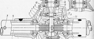
Design and adjustment of the front axle UAZ-3303, UAZ-3909, 2206
The front axle of the UAZ-3303, UAZ-3909, 2206 is the drive axle.
The crankcase, final drive and differential of the front axle do not differ from the corresponding parts and assemblies of the rear axle. All disassembly, assembly, maintenance, adjustment and possible malfunction operations are the same as for the rear axle.
The design of the steering knuckle of the front drive axle UAZ-3303, UAZ-3909, 2206 is shown in Fig. 1.
A ball joint 6 with 30 pin bushings pressed into it is attached to the housing 2 of the axle shaft with five bolts.
The steering knuckle housing 7 is mounted on the ball joint using two kingpins 9.
Rice. 1. Steering knuckle of the front drive axle UAZ-3909, UAZ-2206, 3303
I - right rotary fist; II - left rotary fist; III - wheel release clutch; a - signal groove; IV - wheel release clutch; b - pointer; 1 - steering knuckle pad; 2 - axle housing; 3.27 - cuffs; 4 - bipod thrust; 5 - gasket; 6 - ball joint; 7 - steering knuckle housing; 8 - steering knuckle lever; 9 - king pin; 10 - grease nipple; 11 - locking pin; 12 - retaining rings; 13 - axle; 14 - wheel hub; 15 - gasket; 16-lock washer; 17 - leading flange; 18 - coupling; 19 - coupling bolt; 20 - retainer ball; 21 - protective cap; 22 - nuts; 23 - bolt; 24 - thrust washer; 25 - hub bearings; 26 - spacer ring; 28 - bottom trim; 29 - support washer; 30 - pin bushing; 31 - adjusting gaskets; 32 - inner seal ring; 33 - partition ring; 34 - outer seal ring; 35 - inner sealing ring; 36 - outer sealing ring; 37 - thrust washers; 38 - hinge; 39 - rotation limitation bolt; 40-stop-wheel rotation limiter; 41-steering rod; 42-disc wheel release clutch
The steering knuckle pins are installed with a preload along their common axis, the value of which is 0.02-0.10 mm.
From turning in the steering knuckle body, the pins are locked with pins 11.
Adjust the preload using shims 31 installed at the top - between the steering knuckle lever (left) 8 or lining (right) 1 and the steering knuckle body, at the bottom - between the linings and the steering knuckle body.
To lubricate the upper kingpins and add lubricant to the ball joint, grease nipples 10 are installed on the steering knuckle lever of UAZ-3303, UAZ-3909, 2206 (left) and on the upper lining of the kingpin (right).
The lower king pins are lubricated by grease supplied by gravity from the ball joint.
A constant velocity joint (CV joint) is installed inside the steering knuckle of the front axle of UAZ-3303, UAZ-3909, 2206.
The design of the hinge ensures the same angular speeds of the drive and driven shafts, regardless of the angle between them.
The hinge consists of two forks, in the curved grooves of which four balls are located.
In the central sockets of the forks there is a fifth ball, which is an adjustment ball and serves to center the forks.
The hinge is limited from longitudinal movement by a thrust washer 3 7.
The inner drive fork of the hinge is connected by splines to the differential side gear.
At the driven end of the hinge knuckle there is a device for disconnecting the front wheels, which consists of a movable coupling 18 mounted on splines and a bolt 19 with a spring and a ball.
The movable coupling is connected by external splines to the internal splines of the drive flange 17, bolted to the wheel hub.
To reduce wear on parts of the front drive axle of the UAZ-3909, UAZ-2206, 3303 and save fuel when operating the vehicle on paved roads, along with turning off the front drive axle, it is advisable to turn off the front wheel hubs.
Why remove the protective cap 21 and, unscrewing the bolt 19, install the coupling in a position where the signal ring groove “a” on its surface is located in the same plane with the end of the flange.
Malfunction of the front axle switch and its elimination
If the front axle switch wears out, delaying the front axle connection may cause the vehicle to get stuck in mud, sand or snow.
Troubleshooting procedure:
1) determine the malfunction of the front axle switch; 2) remove the faulty switch; 3) check the operation of the installed switch before lowering the lift struts; 4) check the inclusion of all-wheel drive during a road test.
Recommendations
The front axle switch is not one of the parts that is checked during regular maintenance. It can fail either from frequent use or completely unexpectedly. If you suspect that your vehicle's four-wheel drive is not engaging due to a faulty front axle switch, have a mechanic inspect and possibly replace the switch.
The front axle switch needs to be replaced when four-wheel drive engages with a delay or does not engage at all.
Is it important to fix this problem?
If you operate the car mainly on asphalt, in good road conditions, the occurrence of this malfunction is not critical. However, if you live in an area that experiences heavy snowfall or enjoy off-road driving, you should avoid situations that might require four-wheel drive until you replace the front axle switch.
Replacing UAZ Patriot axle seals
How to replace the rear axle oil seal. Replacing the axle gear oil seal on a UAZ Patriot: Correctly installed high-quality oil seals last a very long time. Never reinstall removed oil seals that have been removed. Buy quality seals. If high-quality oil seals quickly begin to leak, then the reason should be sought not in the oil seals, but in the adjustment of the axle, the fastening and quality of the propeller shaft, the crosspieces, and the suspension bearing. — Unscrew the driveshaft. — Unscrew the nut securing the flange (nut of the drive gear shaft of the rear axle gearbox). — Remove the flange. — Remove the oil seal from the neck of the gearbox using a flat-head screwdriver. — Clean the oil seal installation area with a degreasing agent (white spirit or kerosene). — Before installation, lubricate the inner part of the oil seal, the one that should be in contact with the shaft and oil, with transmission oil. — When installing, an old oil seal is sometimes used as a pressure test. It is advisable to rinse such an oil seal so as not to cause an infection. — The process of installing the oil seal in place must be careful, without distortion both as a result of installation and during the pressing process. — After installation, the inner (working) part of the oil seal, i.e. friction points, lubricate again with the fluid in which it will work - transmission oil. — Install the parts in reverse order. When installing the flange, when tightening the nut, turn it past the flange so that the bearing rollers snap into place.
Adjusting the main pair of the UAZ Patriot axle
1 - bolt; 2, 33 — spring washers; 3 - driven gear; 4, 24 — axle shafts; 5 — adjusting ring; 6, 22 — bearings; 7 — spacer sleeve; 8 — outer race of the outer roller bearing; 9 — roller bearing; 10 — thrust ring; 11 — oil seal; 12 - reflector; 13- flange; 14 — washer; 15 — nut; 16 — axle housing; 17 — adjusting ring of the drive gear; 18 — outer race of the internal roller bearing; 19 — internal roller bearing; 20 — oil deflector ring; 21 — shaft with drive gear; 23 — adjusting nut of differential bearings; 25, 39 — right and left parts of the differential housing; 26 - bolt; 27, 40 - support washers for axle gears; 28, 43 — axle gears; 29, 45 — differential satellite axes; 30, 41, 44, 46 — differential satellites; 31, 38 — differential bearing covers; 32 — retainer for the differential bearing adjusting nut; 34, 36, 37 — bolts; 35 — main gear housing cover; 42 — final drive housing cover gasket
The UAZ Patriot axle is adjusted by selecting adjusting rings and tightening the differential and final drive bearings. The selection of adjusting rings ensures correct engagement of the main gear gears. The correct engagement of the main gear gears is checked by the contact patch. The correct tightening of bearings is determined by the total torque, the value of which is measured in Nm. Naturally, in practice no one is interested in these units of measurement. The process of tightening bearings is determined solely by the ability and experience of the technician. To check that the bridge is configured correctly, special measuring instruments are used.
After repairing and adjusting the UAZ Patriot axle, it should not “buzz” from the very beginning of operation. If the bridge hums during the first days of operation, then after running-in the hum will not disappear. During running-in, a serviceable and correctly adjusted bridge does not hum. Without proper repairs, “humming” bridges will not hum less.
Removing the faulty unit
Since the UAZ 3741 has a frame structure, removing the front axle is quite easy. To do this, you need to stock up on a powerful jack, stops that can withstand 1.5 tons of weight of the front part of the car, and a special liquid for loosening nuts - WD-40.
The procedure is as follows.
- First, you need to place chocks under the rear wheels.
- Then you need to disconnect the right and left brake pipes from the rubber hoses going to the brake drums of the front wheels.
- After this, unscrew the nuts securing the brake hoses and remove the hoses themselves.
- Next, you need to unscrew the nuts that secure the lower ends of the shock absorbers.
- After this, you need to unscrew the bolts connecting the front driveshaft to the drive gear flange.
- Then you should undo the cotter pin and unscrew the bipod ball pin nut.
- Next, you need to disconnect the rod from the bipod.
- Now you need to unscrew the nuts securing the stepladders of the front springs, remove the stepladders along with the pads and pads.
- Finally, you should lift the front of the car by the frame and pull the axle out from under the car.
After the old bridge is removed, you can begin installing the new part, performing the steps in reverse order. If necessary, the removed unit is disassembled, troubleshooting is carried out, damaged parts are replaced and the bridge is installed back.
Maintenance
Maintenance of the UAZ bridge is simple and comes down to monitoring the level of lubricant and topping it up and replacing it. The second point is to check the seals for leaks. It is regularly necessary to check the reliability of the fastenings, especially if the machine is used in difficult road conditions. Eliminate axial play in the differential bearings in a timely manner.
Assembly and connection diagram
When assembling the structure, do not remember several features:
- Press the bushing into the trunnion flush with the end of the washer socket. After completing the procedure, the sleeve must be deployed;
- Place one thrust washer inside the trunnion, the second - in the support. The oil lines in the thrust washers should face the joint. The washer is secured by punching in 3-4 places;
- When installing the hinge, add lubricant to the ball joint;
- Treat the pins and bushings with liquid lubricant.
To obtain the required axial tension, you need to select a certain number of spacers (but not less than five). They are installed on the ends of the knuckle body at the top and bottom. Their number should be the same. Soak the felt ring of the ball joint oil seal with engine oil. If possible, check the bridge on a bench after assembly. If the assembly is done correctly, the axle shafts should not heat up or make excessive noise when braking. Leaks through seals, cuffs, and bolted connections are not allowed.
How to disassemble a bridge
The first step is to remove the brake drum. Next, the hubs and hubs are dismantled. Along the way, inspect the bearings, which may have worn out and will have to buy new ones.
- Unscrew the brake system hose, it will get in the way, and remove the brake shield;
- Pull out the CV joint;
- Remove the rotating mechanism and shank;
- Divide the stocking into two parts;
- Remove the pair from one part of the bridge and the other.
Dismantling the bridge when the car is in a hanging position
How to check the correct adjustment of the UAZ Patriot axle.
To check the correct adjustment of the UAZ Patriot axle, it is not at all necessary to know how to adjust it.
Before you do anything, check the temperature of the axle after driving fast. If the bridge gets very hot, then we can definitely say that it, at a minimum, needs to be adjusted. If such a bridge is not repaired, then sooner or later it will jam. 1. Unscrew the cardan from the bridge. With the car raised, rotating the axle flange (the universal joint mounting point) by hand in both directions, you can feel the presence of broken teeth, assess the condition of the bearings and other problems. 2. After removing the bridge cover, check the condition of the teeth on the main gear and differential by rotating the bridge. There should be no cracks, wear, roughness in the contact patch, cuts or torn teeth. Assess the location of the contact patch. In the crankcase you can sometimes find the remains of destroyed adjusting rings and broken elements. The problems listed above actually exist. If everything is intact, then the bridge can be adjusted. If there are problems, then... 3. Check for transverse clearances in the bearings. If there are gaps, then the bridge must be adjusted before it jams. 4. Check that the final drive is properly engaged. To do this, paint the teeth of the main gear with paint from an aerosol can and, turning the bridge in both directions, determine the pattern of engagement marks. The following figure shows the correct location of the contact patch on the teeth of the final drive gears of the UAZ Patriot axle. The following photo shows an example of incorrect adjustment of the main pair and the presence of roughness at the contact points:
After adjusting the rear axle, there should be no axial play in the bearings of the main gear drive gear and in the bearings of the final drive differential. The axial clearance in the bearings of the bridge is the main reason for its noise and jamming due to the destruction of the teeth in the main pair. There are very few craftsmen who know how to correctly adjust the main pair of the bridge. Instructions on the Internet are not very helpful, since the process is iterative, requiring not only ability, but also experience. We specialize in drive axle alignment. People come to us from other cities on the recommendations of our clients to rebuild drive axles and gearboxes, including foreign cars. Drive axles, aluminum and UAZ tuning are our competitive advantage.
Change of oil
The UAZ Patriot transmission should be filled with the highest quality oil that you can afford.
Too little quality can leak through low-quality seals. Very often, in the rear axle, over time, due to moisture getting into it, the oil turns into a thick, non-flowing liquid. Simply changing the oil in such a bridge does not have the desired effect. If you are not sure, remove the axle and axle cover and clean the axle. Do not have any illusions - if the breathers are not removed, if you drove on water, if a lot of time has passed, etc., then there is no longer oil in the bridge. Moreover, the slurry is not in the gearbox, but closer to the hubs. Those. The rear axle wheel bearings are practically not lubricated.
Breathers. Exiting breathers into the engine compartment
We recommend that absolutely everyone do this modification, especially since the costs for it are relatively small.
Breathers on bridges must be brought into the engine compartment so that water does not get into the bridge under any circumstances. For this purpose, brake hoses and brake pipes are usually used. It is easier to use oil resistant hoses.
At the end of the tubes under the hood, a plastic fine fuel filter from the classics is installed so that dust does not get into the bridge. In this case, the end of the tube is bent down so that water does not get into the bridge even if the car goes into more water than the location of the end of the tubes.
On cars with a compressor, during extreme operation, they sometimes create excess air pressure in the transmission - as if they inflate the axles, gearbox and transfer case from the inside. This completely prevents water and dirt from getting inside and well lubricates the oil seals in areas of friction.
Sometimes an expansion tank with a balloon is installed at the end of the tube to create volume. In this case, the connection between the internal space of the bridge and the atmosphere is completely closed. As the volume of air in the bridge changes during heating and cooling, the balloon inflates or contracts.
If you have driven through a ford with a depth of more than 30 cm, then you should immediately (on the same day) change the oil in the transmission - these are the manufacturer’s instructions. Draw conclusions.
Disassembling the steering knuckle without dismantling the bridge
To perform this operation, first disconnect the hub by unscrewing the 6 bolts. Then bend back the lock washer, unscrew the hub nuts and remove it with the wheel and drum. Further:
- disconnect the oil deflector by unscrewing 6 bolts;
- remove a couple of bolts on the steering knuckle, hang the brake shield on the spring;
- remove 6 bolts to disconnect the cover and the knuckle body;
- to remove it, unscrew the bolts and remove the o-rings;
- Unscrew the knuckle linings, remove the kingpins and remove the steering knuckle housing.
As you can see, it is quite possible to repair the front axle of a UAZ with your own hands. However, you need to have experience in carrying out such work and a good set of tools.
If you have any questions, leave them in the comments below the article. We or our visitors will be happy to answer them
Source