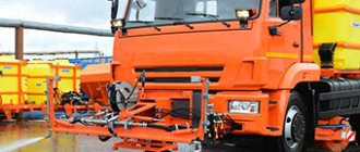
Technical support for public utilities includes a lot of road vehicles. Seasonal equipment of this kind includes watering vehicles. In the summer, they rid the streets of dust and dirt, thereby ensuring the cleanliness of hard surfaces. In addition, road and municipal equipment with an irrigation function also irrigates green spaces. These and other capabilities of such machines are determined by the characteristics of the working bodies and the presence of optional devices.
General information about watering machines
There are two main types of watering vehicles. Representatives of the first category perform exclusively watering tasks, thus ridding the air and road surfaces of dust. The second group consists of modifications that have an expanded range of devices for washing and cleaning. We can say that this is a watering machine, the list of tasks of which includes caring for road infrastructure. Despite the importance of the irrigation function, this technique is not considered as a separate type. As a rule, these are universal cars, the base of which allows, depending on current needs, the use of one or another functional equipment.
Main characteristics
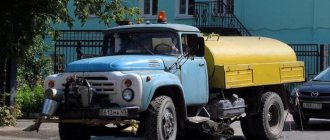
One of the key performance indicators of watering vehicles is the operational capabilities of the tank. The technical infrastructure of such a machine, which ensures the execution of work operations, may change, but the tank and its parameters, as a rule, remain the same. For example, the ZIL watering machine, modification number 130, is equipped with a tank with a capacity of 6 m3. At the same time, the presence of a multistage pump in the working structure makes it possible to maintain a stable pressure in the tank at the level of 25 atm.
Therefore, if there is a need, water can be supplied to several consumers at once. At the same time, it would be wrong to consider the functionality of the machine in isolation from the basic power basis. The power of the car in the same modification is 150 hp. s., which makes it possible to serve large areas. A large water tank also requires high power output from the engine, the load from which falls on the chassis platform. Another thing is that in terms of maneuverability, such a technique is far from ideal. The same applies to fuel consumption. For 100 km of travel, the car consumes about 32 liters of fuel mixture.
Watering machines based on KAMAZ, MAZ, ZIL, GAZ - technical characteristics of the models
| Brand/Model | Sand bunker | Water tank volume, l | Basic chassis | Washing area comb/side nozzles, m | Irrigation zone, m | Brush area, m | Total weight, t |
Watering machine KDM based on KAMAZ - technical characteristics | |||||||
| KDM-316 | order | 10000 | KAMAZ-65115 | 3/ 12 | 14 | 2,4 | 21,3 |
Watering machines KO based on ZIL, KAMAZ - technical characteristics | |||||||
| KO-829AD | order | 6000 | ZIL-497442 | -/8 | 20 | 2,5 | 11 |
| KO-829A | order | 6000 | ZIL-443362 | -/8 | 20 | 2,5 | 11,2 |
| KO-829D | order | 8500 | KAMAZ-53605 | -/8 | 20 | 2,5 | 17,5 |
| KO-829B | order | 13500 | KAMAZ-65115 | -/8 | 20 | 2,5 | 24 |
Irrigation technique
To perform watering, the machine and its working parts must perform several operations, which are controlled by the driver. From the tank, water flows to a centrifugal pump, after which it goes through a filtration stage. The liquid is then directed through a pipeline to the working nozzles. The rest of the work process depends on what capabilities the specific modification of the irrigation machine has. The most modern models have complex systems for distributing liquid between several working sectors. For example, one part may be responsible for watering the road, another for irrigating green spaces, and a third for cleaning the surface.
Sprinkler DF-120 "Dnepr"
The DF-120 “Dnepr” sprinkler is designed for watering all agricultural crops, meadows and pastures with a plant height of no more than 2 m. Watering is carried out positionally from hydrants 2, 3 and 5 (Figure 122) of a closed irrigation network located at a distance of 54 m. The machine is equipped with self-propelled carts-supports 7, on which the water supply pipeline rests 8, 9 flaps, 10 medium-jet sprinklers, 6 intake devices. The flaps and links have stabilizing cable braces and braces.
Figure 122 — Diagram of the DF-120 “Dnepr” sprinkler: 1, 11 — pipelines; 2, 3, 5 — hydrants; 4 - power plant; 6 — intake devices; 7 — support trolley; 9 — postcards; 10 — sprinklers
To drive the wheels, electric motors with starting equipment are mounted on the carts. The electric motors receive power from power station 4 (tractor with mounted generator).
The pipeline is connected to one of the hydrants of the irrigation network and watering is carried out. At the end of watering, the hydrant 3 is closed, the intake device 6 is moved to the transport position, the pipeline is freed from water and the connectors of the power cables of the carts are connected to the power station.
The machine and tractor move synchronously to the next hydrant. The straightness of the pipeline is ensured by a mechanism for synchronizing the movement of trolleys. If any trolley comes forward, the magnetic starter turns off the gear motor and the trolley stops. If there is an unacceptable bend in the pipeline, the warning light on the control panel goes out and the sound signal sounds.
The distance of the machine from the hydrant line is adjusted by changing the speed of movement of the first and last carts using buttons on the control panel in the tractor cabin. To transport the machine from one field to another, the wheels of the carts are turned at an angle of 90°.
With an irrigation rate of 600 m3, a tractor operator serves 1-4 machines, an electrician - 4-8 machines. The productivity of the machine at an irrigation rate of 300 m3/ha is 1.4 ha/h. Rain intensity - 0.3 mm/min.
The main device of a watering vehicle
As already noted, watering vehicles are distinguished by the presence of a tank that contains water. Inside the tank there is also a filter, piping, a sump and a valve. To prevent pumping of water in the tank, breakwaters are usually used in the design. In addition to the main container, it is also practiced to install add-ons in the form of an add-on. Moreover, the modification of the Zilov car 130-P allows the connection of a second tank. The additional water tank is a trailed design, increasing the main volume of liquid by 5 thousand liters. Such tanks are equipped with a plug valve and a sump. Through the central valve, the water supply is regulated with a certain pressure power. Again, to minimize the negative factors from using a large water tank, the designers of such cars use dependent suspensions on longitudinal springs. The front part is usually provided by double-acting hydraulic shock absorbers, and the rear by additional springs. This configuration helps to comfortably overcome problem sections of the road with unsatisfactory surface characteristics.
Self-propelled sprinkler machine DMU "Fregat"
The self-propelled sprinkler machine DMU "Fregat" is a multi-support pipeline 3 moving in a circle (Figure 123) made of steel pipes of a special assortment, installed on two-wheeled carts 4. The pipeline is connected to the riser 2 of the hydrant 1, located in the center of the irrigated area. Above the hydrant there is a fixed support with a rotating elbow, around which the machine rotates.
Figure 123 — Diagram of the DMU “Fregat” sprinkler: a — general view; b - hydraulic drive diagram; 1 - hydrant; 2 - riser; 3 - pipeline; 4 - trolley; 5 - cable; 6 — sprinklers; 7 - drain valves; 9.21 — springs; 10.19 - thrust; 11 - mercury switch; 12 — rod; 20.25 — levers; 14, 26 — throttle and distribution valves; 15,16 - sleeves; 17 - filter; 18 - pin; 22, 27 — pushers; 23 - stopper; 24 - drain valve; 28 — rod; 29 — hydraulic cylinder; 30 - drain pipe
The pipeline is equipped with 6 circular medium-jet sprinklers and a long-range end-sprinkler for irrigating the corners of a square field, irrigating over a sector with a radius of 25 m.
Each cart is equipped with a hydraulic drive that operates under the pressure of irrigation water as follows.
Water from pipeline 3 through filter 17 and sleeve 16 enters throttle valve 14, and then through sleeve 15, distribution valve 26 and hollow rod 28 into hydraulic cylinder 29. Since the hydraulic cylinder rod is fixed to the frame and the cylinder is free, it is under water pressure rises up. A lever 20 is attached to the cylinder, the opposite end of which is connected to the front 27 and rear 22 wheel pushers, which grab the spurs with stops and rotate the wheels.
The shift rod 19, sliding inside the upper part of the lever 20, is connected by the control valve fork to the lever 25. The lever 20 presses the rod pin, it rises and turns the lever 25, which acts through the rod on the valve 26 and lowers it. The latter shuts off the water supply to the hydraulic cylinder and opens the drain hole. Under the action of the return spring 21 and its own weight, the hydraulic cylinder lowers and pushes water to drain into pipe 30. The wheel pushers move back and engage with the following lugs. Having reached the fork on the rod, lever 20 presses on it, turns lever 25, which, grasping the collar of the rod, opens the valve and closes the drain hole. Water enters the hydraulic cylinder and the cycle repeats.
The carts, being at unequal distances from the center of rotation, move at different speeds, so each of them has a speed control mechanism. If one of the trolleys lags behind, the pipeline bends and pulls the rods 10 attached to it, moving the rod 12, which presses with a bevel on the roller of the pressure lever 13, and that, in turn, on the throttle valve rod, forcing the valve 14 to lower. The valve opening increases, the hydraulic cylinder fills with water faster, and the speed of the trolley increases. This continues until the cart is in line with the others. When the bend in the pipelines is leveled out, the water supply will return to normal. The speed of movement of the trolley is adjusted by changing the working length of the rod 12.
The rotational speed of the machine (0.47-0.11 rpm), and therefore the irrigation rate (240-1250 m3/ha), is manually adjusted on the last trolley using a valve - a speed controller, which changes the water supply to its hydraulic drive. The tap is equipped with an arrow and a scale. After supplying the irrigation rate, the machine is transported to the next hydrant.
The machine is manufactured in several modifications with the number of ax carts 7-20. Fregat-1 is equipped with a pipeline with a diameter of 152.4 mm and flexible inserts. It is used in areas with particularly difficult terrain, where the difference in local slopes along the pipeline of each cart relative to neighboring ones is 0.08-0.22°. Fregat-2 has a pipeline with a diameter of 177.8 and 152.4 mm without flexible inserts. It is used in areas with a local slope along the pipeline not exceeding 0.08°.
Fregat machines irrigate all field crops, meadows and pastures with plant heights up to 2.2 m. One mechanic services 3-4 machines. The machine can be equipped with a hydraulic feeder. Rain intensity 0.25 mm/min.
Functional elements of the machine
In addition to the metal tank, the functional equipment may include a wide range of different nozzles, water supply hoses and brushes. The working parts of the watering vehicle are distributed over several sections, which are connected to each other by pipelines. The working infrastructure also includes a water pump, a central valve, a strainer and piping systems with rotary nozzles. The equipment is mounted on a truck platform with reinforced springs. The water-distributing pump of the irrigation machine ensures that irrigation is carried out in conjunction with other operations. Thus, some modifications are equipped with plow and brush equipment, which allows the equipment to be used as a harvesting machine. Sometimes such models are supplemented with means of sprinkling the coating with inert substances, which increases the efficiency of the cleaning function.
Double-cantilever sprinkler unit DDA-100ВХ
The DDA-100VH double-cantilever sprinkler unit (Figure 125) is used for watering vegetable, industrial and grain crops. The unit, moving along the irrigation canal, distributes water across its working width in the form of rain. It is mounted on a DT-75M tractor equipped with a creeper.
Figure 125 — Sprinkler unit DDA-100ВХ: a — general fork; b - diagram of water movement in the farm; 1 - suction pipe; 2 - floating valve; 3 - farm pipeline; 4 - hydraulic feeder; 5 - frame; 6 — gas jet ejector; 7 — supporting arc; 8 — postcards with attachments; 9 — end nozzle; 10 - farm; 11 — turntable; 12 - pump
Centrifugal pump 12 sucks water through the floating valve 2 and supplies it to the pipeline of the turntable 11 and the lower pipeline 3 of the farm 10. From here, the water flows through the openings 8 into fifty-two short-jet and two end nozzles 9. To apply fertilizer solutions, a hydraulic feeder 4 is connected to the unit.
The 8K-12 centrifugal pump, mounted on the rear axle housing of the tractor, is connected to a reduction drive.
The truss 10, composed of a turntable 11, made in the form of a pipe, and two consoles, rests on roller supports of the frame 5. A check valve and a pressure line from the pump are connected to the circle pipe. The valve prevents air from pipe 3 from entering the pump during ejector operation. Water flows from the circle pipe into pipeline 3 through four pipes. Pipelines 3 are equipped with drain valves and openers 8 with short-flow nozzles.
The nozzles are located symmetrically relative to the longitudinal axis of the console with a distance of 4 m along the length of the truss. On panels from the first to the seventh (counting from the circle) the nozzles have a nozzle diameter of 12 mm (28 nozzles in total), from the eighth to the eleventh - 13 mm (16 nozzles), on the twelfth and thirteenth panels - 14 mm (8 nozzles). This ensures the same water flow (2.3 l/s) for each nozzle and its uniform distribution over the irrigated area.
End jet nozzles with a diameter of 22 mm and a flow rate of 5 l/s have a divider, the movement of which regulates the spray range.
To control the operating mode of the pump during irrigation, a pressure gauge and a vacuum gauge are installed on the unit. During normal operation of the unit, the pressure gauge needle is set at 0.3 MPa, and the vacuum gauge - 0.03-0.04 MPa. The pump is turned on from the tractor cab.
The floating valve 2 is installed on the suction pipe 1, made up of two elbows with articulated couplings. Rubber gaskets are used to seal the connections. The valve is raised to the transport position and lowered into the working position by a hydraulic cylinder. The valve float has a mesh and a slide that holds the mesh above the bottom of the channel at a distance of at least 10 cm. The normal immersion depth of the mesh is 10-15 cm, so filling the sprinkler with water when watering should be at least 0.4 m.
A water meter is installed on the suction pipeline. Before putting the unit into operation, air is pumped out from the suction line and the pump using an ejector 6 installed on the exhaust pipe of the tractor. The working width of the unit is 120 m.
To use DDA-100ВХ, a network of irrigation canals with a length of 200 to 1200 m is cut. Irrigation is carried out in sections with a length of 100 to 300 m. Areas of simultaneous irrigation (pools) are separated by jumpers. The layer of sediment in one pass of the unit depends on its operating speed. If 5 mm of precipitation falls in one pass of the unit (50 m3/ha), then with an irrigation rate of 200 m3Da the unit must make four passes, with 300 m3Da - six, etc.
It is advisable to start watering from the head area. The unit can be transported to the next site in working position. If obstacles are encountered, the farm is positioned along the longitudinal axis of the tractor.
Having freed the circle from the connections with the pump and supports, as well as from the fastenings to the hydraulic cylinder rods, the truss is turned with the tractor stationary or the tractor is turned while holding it by the arcs.
For irrigation at night, two lights are installed on the upper belt of the farm, illuminating the supporting arches of the consoles. The road for the unit must be provided along the sprinkler on the right side downstream.
Additional functionality
Watering vehicles can also be used as fire trucks and transport vehicles. In the first case, the machine is equipped with a fire hose equipped with a jet supply barrel with high pressure force. Of course, there is no need to talk about a full-fledged fire extinguishing function, but a sprinkler can be considered as an auxiliary equipment of this type. When the hose is working, all valves and taps are tightly screwed on, which allows increasing the pressure power and the effectiveness of fire fighting. For the transport function, modifications with two tanks are usually used. These vehicles are used to transport water to service facilities remote from public infrastructure.
Sprinkler DKSh-64 "Volzhanka"
The DKSh-64 Volzhanka sprinkler is designed for watering low-stemmed field and vegetable crops, as well as long-term cultivated pastures and meadows. The machine has two wings 4 and 11 (Figure 121), which, when watering, are mounted on both sides of the irrigation pipeline 1.
Figure 121 — Diagram of the DKSh-64 “Volzhanka” sprinkler: a — general view; b - drain valve; 2.12 - hydrants; 3 - feeders; 4.11 - wings; 5.10 — wheels; 7 — sprinkler; 8 — drive trolley; 9 - engine; 14 — drain holes; 15 - bolt; 16 - valve
Watering with each wing is carried out positionally with water taken from hydrants 2 and 12, located one from the other at a distance of 18 m.
Each wing consists of a water supply pipeline 6, support wheels 5, a drive trolley 8 and sprinklers.
The pipeline is assembled from aluminum pipes 12.6 m long, which simultaneously serve as the axis of support wheels 5.
Medium jet sprinklers 7 are equipped with self-installation and barrel rotation mechanisms. The self-aligning mechanism is a tubular hinged link with a sealing washer and a counterweight. When watering, counterweights hold the devices in a vertical position. The barrel rotation mechanism is equipped with a swinging rocker arm with a blade. A stream of water coming out of the apparatus nozzle hits the rocker arm blade and deflects it. Returning to its original position, the rocker rotates the barrel of the apparatus at an angle of 3-5°. Nozzle hole diameter 7 mm.
A drain valve 16 is mounted on the flange of each pipe, consisting of a metal plate and an oval-shaped rubber cuff. After closing the hydrant valve, the cuffs move away from the holes 14 and release water from the pipe. When watering, the cuffs cover holes 14.
From one position to another, each wing is rolled using a 3 kW gasoline engine 9 mounted on a wing trolley. Engine 9 drives the running wheels 10 of the trolley and the irrigation pipeline 6.
Using the reverse handle, you can stop the machine and give it forward and reverse motion. The handle is turned on before starting the engine or at a low speed when the engine clutch is disengaged.
Pipeline 6 is assembled at the edge of the field opposite the hydrant and connected to it with a flexible hose. After issuing the irrigation norm, close the hydrant valve, disconnect the hose from it, turn on the engine, roll the first wing to a new position, and install the devices in a vertical position. After turning off the engine, the pipeline is connected to the next hydrant and watering begins. The second wing is connected to the first hydrant and put into operation. Both wings are watered at the same time.
The sprinkler is available in six modifications with wings of length 400, 350, 300, 250, 200 and 150 m. One operator serves two or three machines. Rain intensity 0.24 mm/min.
Mini watering machine
Small watering machines are distinguished by a modest tank volume and corresponding parameters for covering the working area. These models include some modifications of the ZIL with a width of the irrigation area of the order of 2-2.5 m. Also, installations with a sprinkling effect can be included in the category of mini-irrigation machines. They are optimally suited for caring for green spaces and for cleaning road surfaces. True, a watering machine in this design has a very small tank volume, which makes it necessary to frequently fill it with water.
Sprinkler "Kuban"
The Kuban sprinkler is designed for watering grain, fodder, vegetable and industrial crops, including tall-stemmed ones, cultivated in areas with calm terrain. The main parts of the machine: power unit 7 (Figure 124) and two sprinkler wings, made up of spans 3 and 4, two-wheeled support trolleys 5, a diesel engine with a power of 158 kW, an electric generator, a centrifugal pump, a water intake 11 with a float 12 are installed on the frame of the power unit and control panel. The frame of the unit is suspended from the central pipeline 6, mounted on the racks of two-wheeled carts 5. To rotate the wheels 14, gear motors 15 and devices for stabilizing the spans one relative to the other (arranged in a line) are mounted on the carts.
Figure 124 - Diagram of the Kuban sprinkler: 1 - console; 2 — sprinkler nozzle; 3, 4 - spans; 5 — support-gender trolley; 6 - central pipeline; 7 — power unit; 3 — course stabilizer; 9 — stabilizing cable; 10 - road; 11 - water intake; 12 — float; 13 - channel; 14 — wheel; 15 — gear motor
A device for stabilizing the vehicle's movement along the course is installed on the right trolley. The device interacts with a cable stretched along the irrigation channel 13 and ensures that the machine moves along a given course.
Short-jet sprinkler nozzles 2 with a hemispherical deflector directing the rain torch in one direction are attached to the water supply pipelines of spans 3 and 4 and consoles 1. Nozzles with even numbers are oriented with the nozzle forward, and with odd numbers, the nozzle is oriented backward relative to the axis of the pipeline. Irrigated areas are located symmetrically on both sides of the irrigation canal. Planned roads 10 are laid along the canal, the surface of which is rolled and compacted.
Watering is carried out while the machine is moving, drawing water from an open irrigation channel. The pump sucks water through the floating float 12 and supplies it to the central pipeline 6, and from it to the water supply pipelines of the spans and consoles. From here, water flows into 294 nozzles and is sprayed in the form of rain, the average droplet size of which is 1.0-1.03 mm. Rain intensity up to 1.3 mm/min.
The machine constantly serves one area 800 m wide and 1500-2500 m long. Watering begins from the middle of the field, moving sequentially back and forth. At the edges of the field, the electric drive is switched to reverse. The irrigation rate is set by changing the speed of movement of the carts using a time relay installed on the control panel. Thanks to automation, the operator can service 2-4 machines.
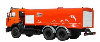
Manufacturers of watering vehicles
In Russia, the majority of watering vehicles are represented by modifications based on the ZIL chassis. Also, public utility vehicle fleets often maintain equipment based on models from the Kama Automobile Plant. This is a productive and powerful watering machine, which not only makes it possible to service large-volume tanks, but also makes it easier to control the working parts. Gradually, this segment is being replenished by foreign technology. For example, during operation, the Haller 9000 model performs well, which is equipped with a large reservoir and provides the user with ample opportunities for optional equipment.