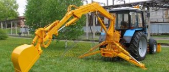
MTZ-based grab loader - what is it and where is it used?
These devices are installed on tractors as attachments.
With the help of a rotating boom, materials can be loaded in any position of the loader.
Grab loaders based on MTZ tractors are produced by several factories and enterprises, the main manufacturer is the Yurga Agricultural Equipment Plant "Yurmash".
The main number of grab devices is installed on the base of agricultural models of tractors MTZ-80 and MTZ-82.1 , using the resources and performance of the Minsk “Belarus”.
MTZ tractors are distinguished by all-season operation and reliable mechanisms. Their high off-road capability is successfully combined with the ability to move on roads in general traffic.
Inexpensive and accessible spare parts are complemented by the versatility of using special equipment:
- loading sand, gravel, snow, construction and other waste and other materials into vehicles;
- excavation work (moving, laying and excavating soil), cleaning the area at a level that may be above or below the level of the car parking;
- digging large and deep (up to 2.5 m) pits with excavation of soil and stone;
- lifting, moving and reloading hay, silage, straw, peat and fertilizers;
- lifting long and oversized objects (timber);
- cleaning of shallow bodies of water (lakes, ponds). Features of the loader and its design
The most popular grab loader at MTZ is the PE-F-1BM; several modifications have been created on its basis.
The main advantages of the grab installation at MTZ:
- multifunctionality;
- favorable price-quality ratio;
- loading capacity = 120 t/hour;
- aggregation (arrangement) of a loader with tractors and trailers, which expands their scope of application;
- Possibility of operation in all weather conditions;
- maintainability and low cost of maintenance of the grab installation.
The grab is used for lifting, reloading and transport work with various materials or piece cargo up to 1 ton.
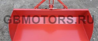
Basic equipment - grab bucket and bulldozer blade (straight type, width = 2 m).
Full set - plus forks (claws), volume = 0.56 m³ for hay, silage and backhoe (volume = 0.27 m³), reinforced high-strength grab, volume = 0.3 m³. As additional options, a hook with a capacity of 1 ton and a drill can be installed.
Rigid suspension loaders
Such units are used for scooping material in large volumes. Used for unloading the holds of ships and wagons.
This grab is installed on a hook cage with a single-drum winch. The design of the unit has an upper head (a drive is installed in it) and jaws secured with hinges. The drive can be of different types:
- Lever.
- Hydraulic.
The mechanism for closing the jaws in such units is built into the design of the grab and is installed on a traverse or lever-screw system. An electrical cable is required to power the drive mechanism. In some models, the closing drive is located on the upper crossbar. With such grabs, the center of gravity is shifted slightly upward. Among the advantages of using loaders with rigid suspension, it is worth noting the compact design, as well as the lifting height. Among the disadvantages is the instability of the grab when scooping material from a slope. In this case, the center of gravity of the device shifts significantly.
We also note that multi-jaw grab loaders are also used in production. They have four to eight load gripping devices. Typically, such devices are used for difficult-to-scoop material. The loader's jaws are crescent-shaped and are attached to the lower cylindrical crossbar by means of hinges. The working angle of the paws ranges from 45 to 120 degrees. By the way, multi-jaw grabs are also used for loading timber. However, to prevent the paws from damaging the tree trunk, they have a flatter shape.
Grab loader based on T 16 - differences and technical parameters
The basic model T-16 was produced by the Kharkov Tractor Plant in 1961-1967.
Later the car was modified and was produced in an improved form until 1996.
Advantages of the HTZ chassis:
- Long service life.
- Low price.
- The tractor weighs 1685 - 1810 kg - it does not compact the top layers of soil.
- It has 2 pairs of wheels of different sizes - smaller front ones and larger rear ones; using the locking mechanism, you can change the track width for both pairs.
- The T-16 chassis has a rear-mounted engine and can be mounted with virtually any front-mounted equipment. There are seats for attachments at the front.
- Tractor engine 25 hp - air-cooled.
Disadvantages of the T-16 : low productivity and the need for regular cleaning of the air valves and centrifuge.
Device and purpose
The technique is used to move various materials using a load gripper with rotating jaws. The machine is a device that is installed on cranes, excavators or tractors. A forklift based on MTZ is often used. This design is used when loading logs or bulk materials.
The design consists of a tractor on which a large iron bucket is mounted, attached to a crane and grasping loads. The machines are also used for digging pits, moving rocks, and breaking concrete. The main indicators of technology are bulk density and load capacity. Loaders come in 4 classes:
Ultra-light ones are used for loading lime or coal dust. Load capacity index - 0.37. Bulk density is 400-630 kg/m³. The lungs are designed for unloading slag, chalk, gravel, and coal. Bulk density - 800-1000 kg/m³. Load capacity index - 0.4.
Medium ones are used for loading alabaster, lump clay, limestone, crushed stone, and cement. Bulk density - 2 t/m³. Load capacity index - 0.42. Heavy ones are used for hard rocks. Bulk density - 2.5-3.2 t/m³. Load capacity index - 0.45.
The ropes in the loader are protected from chafing when grabbed by a bucket. The grader blocks are installed in such a way as to prevent the ropes from falling out.
Grab loaders are:
Rope cars have a replaceable load-handling device. The grab is hung on a hook clip. In such designs there is a lock connecting the traverse to the holder, which is made with a pulley block. Rope loaders have a bulk density of 500-2000 kg/m³. Such devices are universal. Since the grab is hung on a hook, the loader can be installed on any tractor, crane or excavator. But such mechanisms have a low lifting height and are controlled manually.
Rigid suspension grabs are designed for scooping large volumes of material.
Machanism is used for unloading railway cars and ship holds. The grab is installed on a hook cage with a winch. The design includes a rotary coupling, an upper head and jaws secured with hinges.
Drive - lever or hydraulic. An electrical cable is required to power the device. Such structures are compact and have a large lifting height. Hydraulic equipment is equipped with oil lines.
There are also multi-jaw grab loaders. They have from 4 to 8 grab grips. The sickle-shaped jaws are fixed on the lower cross-beam.
Characteristic
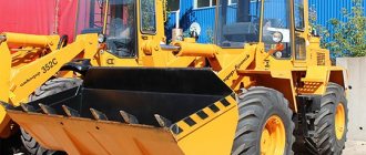
This name comes from the German word “greifen”, which literally translates as “grab”. This unit is a load-handling device that is installed on cranes, excavators, as well as tracked and wheeled tractors. Very often you can find a grab loader based on MTZ. This technique is used for loading long timber and bulk cargo.
Externally, a grab loader looks like an ordinary tractor or excavator, at the end of which there is a large iron bucket. It is he who attaches to the crane and grabs various materials for loading and unloading. It is worth noting that such loaders are used not only for bulk cargo and timber. The grab can also dig deep pits, lift rocks and break concrete (but in the latter case you need a special, powerful grab with strong paws).
Model overview
There are different models of grab loaders available. Let's look at the most popular grab loaders that are most often used.
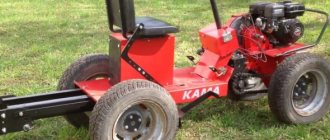
Karpatets PEA 1A
Karpatets PEA 1A is designed for loading, excavating and leveling work. It is used when greater lifting capacity, speed and boom reach are needed. The mechanism performs work without moving due to the large angle of rotation of the boom.
- Loading capacity - 1 t.
- The grab volume is 0.67 m³.
- Productivity - 240 t/h.
- Turning radius - 270º.
- The loading height with a grab is 4.3 m.
- The maximum digging depth with an excavator shovel is 2.5 m.
- The volume of the excavator shovel is 0.44 m³.
- The width of the excavator shovel is 0.7 m.
- The width of the bulldozer blade is 2.45 m.
- The height of the bulldozer blade is 0.73 m.
- Ground clearance - 0.4 m.
- Travel speed is 25 km/h.
- Dimensions - 6.75x2.20x2.67 m.
- Weight - 7575 kg.
Features of using forklifts
Such machines are mainly made on the basis of excavator equipment. Thanks to a special device, the grab easily grabs and carries the load. The basis of the gripping mechanism is hydraulics or a rope-drive system. Hydraulics are quieter and more mobile, and rope hydraulics are more productive.
The hydraulic drive system provides reliable grip of the load. If you plan to unload metal, it is better to use GA buckets. They are equipped with larger diameter hydraulic cylinders. For work with soil, BA grips are used, and for reloading timber - PB. Important components are reliably protected from accidental damage.
Grab loaders are used on construction sites. They significantly increase the efficiency and speed of work. It is impossible to do without such equipment when implementing a large-scale project.
Grab loaders are used for the following purposes:
- moving long cargo;
- transshipment of bulk building materials - frozen soil, crushed stone;
- transshipment of large cargo.
The capabilities of the loader depend on the type of gripper, which can be open or closed. Loading capacity depends on the choice of model and can range from 8 tons, 8-16 tons, more than 16 tons.
How to make it yourself
A homemade hand grab is not difficult to make.
Materials and tools:
- steel 2 mm thick;
- pipes of different diameters;
- chain;
- welding machine;
- cutter.
A rectangular plate 550x22 mm is cut out of a steel sheet. It needs to be divided into 2 parts, cut not in a straight line, but in a zigzag. This will create teeth. Each tooth should be 15 mm long. Now the sides are done. The bottom plates should not be horizontal; an angle of 15º should be maintained between them and the ground.
Then plates are cut out 40 mm wide and 220 mm high. Then you need to step back 5 cm from the edge of the front part of the side and weld the plates so that they meet in the center of their edge. The plates at one end are welded to the outside of the side.
At the second edge they are welded onto the side. Then you need to trim them so that they are the same length. Now take the pipes, one should scroll inside the other. A hole is made in the ladle plates for the pipe. They put it in a plate and weld it. The same steps are performed for the second pipe.
Ballast of 5 kg on each side is welded at the ends. Handrails are attached. One chain is mounted to the center of the handrails. You need 2 chains 1 m long. They are attached to the edges of the central pipe. The other ends are connected and suspended on one chain.
Autonomous loader-excavator PEA-1.0 “Karpatets”
Photos in the album “Tractors”, by l angeo
on Yandex.Photos
Autonomous loader-excavator PEA-1.0 "Karpatets" - with a lifting capacity of 1.0 tons, self-propelled grab, universal, designed for loading organic and mineral fertilizers, bulk and low-bulk materials, piece and bagged agricultural cargo, silage, haylage, as well as for excavation work in soils up to category III and bulldozer work within the limits of traction force. The PEA-1.0 backhoe loader is a further improvement of the PE-0.8B loader with design changes to the YuMZ tractor chassis: shifting the column, changing the wheel arrangement, hydraulic system and boom design. It consists of the following components and mechanisms: frame, engine, transmission, chassis system with brakes, steering, cabin, working equipment, hydraulic system and electrical equipment. The power unit assembly, which includes an engine, clutch, rear axle, gearbox and final drives, is attached to the frame, unified with the YuMZ-6L tractor. Four-stroke diesel engine D-65N with a power of 60 hp. The transmission consists of a gearbox, clutches and connecting main gear, differential, final drive and final drives; chassis system - from the front axle, front and rear wheels; steering - from a column with a steering wheel, a steering mechanism and a longitudinal rod. The cabin is all-metal, with a single swivel sprung seat and a hydraulic shock absorber. Equipped with electric windshield wipers, rear-view mirrors, fan, courtesy light, sun visor, first aid kit drawer, thermos, coat hook and space for a tool bag. Overall dimensions 6300 x 2500 x 3500 mm. The working equipment consists of a frame, jacks, a bulldozer, a rotating part, and replaceable working parts. The hydraulic system consists of two subsystems with a common hydraulic tank. The first subsystem is the hydraulic drive of the bulldozer, powered by an NSh-32 hydraulic pump, the second is the hydraulic drive of the loading system, powered by two NSh-50 hydraulic pumps. Load capacity - 1 t, boom reach - 4.5 m, height - 4.3 m, grab - 1 m3, digging depth - 2.60 m, digging radius - 5.50 m.
Rice. 1. Diagram of the hydraulic mechanism of the PG-05m grab loader
These pumps drive the boom lift power cylinders, the grab cylinders and the boom bend cylinder.
The NSh-16V pump is installed on the loader, is driven by the power take-off shaft and drives the jack cylinders and the column rotation cylinder. A significant factor that determines the performance of a loader is the technical condition of the hydraulic system components of the loader. Therefore, a tractor driver operating a loader first of all needs to know the structure of the hydraulic system, its malfunctions and be able to eliminate them.
1. Design of the hydraulic mechanism of a grab loader
The hydraulic system of the grab loader uses gear pumps NSh-16V, NSh-40V and distributors R40/75B, the design and operation of which will not be discussed here.
The grab loader consists of the following components and mechanisms: frame, column, boom, boom extension, grab, grab extension, jacks (hydraulic supports), gearbox for driving the NSh-16V pump, manure claws and hay grab, hook, universal grab, bracket for installing the grab in the transport position, swivel seat and hydraulic system components.
The loader frame is a welded structure. The shape of the frame is very similar to the frame of the E-153 excavator, which was mentioned earlier. The frame is suspended from the bottom of the tractor and is attached at the front to the semi-frame of the tractor, and at the rear to the sleeves of the tractor axle shafts.
A rotary column is installed on the protruding part of the frame at the rear.
The purpose of the PG-0.5 m loader column is similar to the rotary column of the E-153 excavator and in some way resembles its design, but has its own fundamental features. These include differences in rotating devices. At the loader column, rotation is carried out using a gear mechanism, which is driven by a double-acting hydraulic cylinder with two pistons.
The rotary column is a welded pipe structure and is installed in a stationary cast-iron housing on two tapered roller bearings. A spur gear c is attached above the lower roller bearing, which meshes with the rack of a two-piston cylinder mounted at the rear of the column housing. The gear rack is cut on the rod in its middle part. Depending on which side the oil pressure is supplied to the pistons, the direction of movement of the rack will also depend. If oil is supplied to the turning cylinder from the right side as the tractor moves, then the rack, moving to the left, will force the column to turn clockwise; and vice versa - when oil is supplied from the left side to the cylinder, the rack will move to the right, the column will turn counterclockwise. The rotating mechanism allows the boom to rotate 315°.
A gear reducer is installed at the front at the bottom of the column to drive the NSh-16V 4 pump.
Rice. 2. Rotary column
R-75B oil flow distributors are installed on the right and left sides of the column.
The boom is attached to the column at two points: the end eye using a special pin with the column head, and in the middle part - through the power cylinder with the column clamp. The internal cavity of the boom is occupied by steel oil pipelines of the hydraulic system. This arrangement of wires ensures their safety and compact design. The boom has powerful power cylinders that provide breaking force on the claws of the grab up to 1000 kg.
The grab mechanism consists of a welded frame, two power cylinders working in tandem, and two halves of the grab bucket. In cases where it is necessary to deliver cargo or material from deep holes or trenches, the grab can be extended using a special extension. In this case, additional oil lines are installed on the grab.
Jacks or supports are intended to unload the drive wheels and ensure a stable position for the tractor when working with a grab. The design of the jacks is similar to the supports of the E-153 excavator. They are equipped with double-acting cylinders of the TsS-100 brand.
Since the loader has a larger number of power cylinders than in a separate tractor system, a second oil tank was installed in the hydraulic mechanism of the loader to ensure normal operation of all power cylinders of the loader.
Installing a second tank simplified the installation diagram of the hydraulic system and provided ease of control of the loader's working parts.
Thus, the hydraulic system of a grab loader has two independent circuits - large and small. The large circuit includes an NSh-40V pump, a P 40/75 distributor, 8 boom power cylinders, a bend cylinder, a grab cylinder and an oil tank. The small circuit includes an NSh-16V pump, a P40/75B distributor, a turning cylinder, jacks, a bypass valve and an oil tank.
The boom rotation cylinder is a double-acting cylinder with two pistons, between which a gear rack is installed. The ends of the cylinder are sealed with lids.
A rotary coupling is installed in the upper part of the rotary column housing, which ensures a continuous supply of injected oil from the distributor to the cylinders and its return from the cylinders to the distributor while the column is rotating. The rotary coupling consists of two parts: a housing and a bushing. On the outside of the body there are a number of ring grooves, evenly spaced in height, and seven grooves for rubber sealing rings. The first six grooves are connected through vertical channels in the housing with oil supply holes, for which six drillings are made in the housing to the level of each annular groove. From below, all drillings are plugged with conical plugs. In the bushing of the rotary coupling, at the level of each oil channel, there is a drilling with threads for fittings, to which are connected oil lines that supply oil to the cylinders for lifting and bending the boom and the grab mechanism.
Rice. 3. Rotary coupling
2. Hydraulic bypass valve
The purpose of the bypass valve is to prevent the boom from suddenly stopping when the oil supply to the swing cylinder is stopped.
Installation of the bypass valve in the rotation cylinder system is shown in Fig. 2, and the device in Fig. 4. The relief valve casting body has a series of holes and channels to accommodate four fittings, four plugs, four springs, four balls and a relief valve. The safety valve is adjusted to a pressure of about 90-100 kg/cm2 and sealed.
Rice. 4. Bypass valve
The operation of the bypass valve is as follows. When the boom is turned to the right, the forced oil flow from the distributor through the cavity of the bypass valve enters the working cavity A of the boom rotation cylinder. The oil displaced from cavity B of the cylinder returns to the distributor through the cavity of the bypass valve. When the distributor handle is set to the neutral position, the supply of oil to cavity A of the cylinder will abruptly stop, and the drainage of oil from cavity B of the cylinder will also stop. Both volumes of oil in the cylinder will be locked. The moving boom of the grab must stop instantly. This does not happen because inertial forces act on the boom and the pressure in cavity B increases sharply. The magnitude of this pressure is so significant that it can cause breakdowns of the gear rotation mechanism. To eliminate this harmful phenomenon, the bypass valve system is designed to relieve excess pressure. It is carried out as follows. At the moment when the oil is squeezed out of cavity B and enters the cavity of the bypass valve, there is no way out towards the distributor, since the path is blocked by the distributor spool. Then the oil, overcoming the elasticity of the spring, squeezes the ball and passes into the cavity, and then, overcoming the safety valve spring, adjusted to 90-100 kg/cm2, enters the cavity and through the cavity through the oil line into cavity A of the power cylinder.
Thus, the system of channels and valves of the bypass valve ensures that during sudden braking of the boom, oil is pumped from one cylinder cavity to another, bypassing the distributor. At the same time, the arrow stops not abruptly, but smoothly.
The hydraulic system of a grab loader has two retarding valves; we have already discussed their purpose earlier. The design of the retarding valve of the grab loader system differs from the retarding valves installed in the power cylinders of separate-unit systems.
Between the spherical surface of the fitting and the valve body, a washer with a calibrated hole of 2 mm is installed in the bore. The fitting is attracted to the retarding valve body by union nut 2. When installing retarding valves, remember that the hoses must be connected from the side of the valve body.
The hydraulic system of the grab loader has eight power cylinders. All of them, except for the boom rotation cylinder, are identical in design and differ from each other in length, diameters and stroke of the piston.
3. The procedure for assembling and installing the loader hydraulic mechanism units on the tractor
Manufacturers do not install the loader on the tractor, so the assembly and mounting of the loader on the tractor is carried out on farms. Inaccurate assembly of the lift's hydraulic components can adversely affect the performance of the forklift.
Before installing the loader, it is necessary to prepare the tractor: 1. Perform daily maintenance. 2. Remove the mounted system, mothball it and put it into storage, place the drive wheels of the tractor on a 1800 mm track, and set the tire pressure within 1.2 (maximum 1.5) kg/cm2.
Then install the loader units on the tractor in the following order.
Prepare fastening material and place the frame on stands so that when the tractor hits the frame, the latter is between the wheels. Attach the front part of the frame to the side members of the tractor half frames. For this purpose, use the holes on the frame side members intended for attaching mounted machines. Strengthen the rear part of the frame at two points: to the sleeves along the axles of the tractor and with special lugs to the axis of the central link of the hitch mechanism.
Rice. 5. Retarding valve
After attaching the frame, attach stands to the side members in the front part of the tractor to install the grab and loader boom in the transport position.
The steering column comes to the farm from the factory in assembled form and is attached to the tractor at two points: on the protruding part of the frame at the back it is bolted to the base, and to the lifting axis of the levers of the mounted system - with a central link.
After installing the column, connect the power take-off shaft to the gearbox of the NSh-16V oil pump.
Place the jacks and begin assembling the boom. It is recommended to first connect the boom to the extension, then connect the boom and extension to the bending power cylinder. Using a bracket and a connecting pin, hinge the boom to the head of the rotary column.
When the boom is connected at one end to the column, you can begin installing the power cylinder for lifting the boom, and then attach the grab mechanism.
When assembling the loader, special attention should be paid to the installation of high-pressure oil lines. Installation of oil lines should be carried out after assembling the loader components. Before installation, wash all internal channels and oil lines with gasoline and blow with compressed air.
The NSh-16V pump is connected by a suction pipe through an oil line to an additional oil tank installed behind the column, and by a discharge pipe to the high pressure channel of the left distributor (along the tractor).
The NSh-40V pump installed on the engine is connected to the right distributor on the column and the oil tank of the separate-aggregate system, but since the distributor of the separate-aggregate system is not removed, but remains on the tractor, its fittings freed from the oil lines must be closed with plugs.
4. Maintenance of the hydraulic system of the grab loader
In summer, the hydraulic system is filled with DP-11 diesel oil, and in winter - with a mixture of diesel oil and spindle oil in equal proportions.
When filling the system with oil, it is necessary to turn on the NSh-16V and NSh-40V pumps and then, by sequentially turning on and off the levers of the P40/75B distributors, fill the working cavities of the cylinders and oil lines.
Operating the forklift with a low oil level in the tank is strictly prohibited.
At low ambient temperatures, before starting work, be sure to lift, lower and rotate the boom several times, open and close the grab so that the hydraulic system components do not experience heavy overload due to the high viscosity of the oil.
During daily inspections, pay special attention to the fastening of the boom rotation cylinder.
Every 200 hours of operation of the loader, change the oil in the system. Before adding fresh oil, flush the system with kerosene. To do this, the oil tank is filled with kerosene, the oil lines and high-pressure hoses are consistently disconnected from all hydraulic cylinders and the pumps are turned on. By sequentially turning on the hydraulic valve handles, kerosene is driven through all channels of the hydraulic system, washing away contaminants. Wash the filter and oil system every 30 hours.
5. Malfunctions of the hydraulic system of the grab loader
Malfunctions in the hydraulic system most often occur from non-compliance with operating rules and less often from violation of adjustments and wear. Here are the most typical malfunctions in the hydraulic system of a grab loader. Malfunctions in the operation of gear pumps and distributors have already been partially discussed above; it will be done here; addition to what was previously stated.
Specifications
Workers of the design bureau, having modernized the previous model, developed the Karpatets PEA 1A. By reducing the total weight by 15%, they increased the maneuverability and carrying capacity of the equipment.
The improved model has the following indicators:
- Length 6 meters, width 2.25 meters, height - almost 4 meters
- Clearance height from the surface is 0.4 meters
- The maximum speed of movement of the unit in operation is 25 km/h
- Loader boom throw length reaches 4.5 meters
- With a maximum digging radius of 5 meters, the trench depth reaches 2.5 meters
- The volume of an excavator shovel reaches 0.7 m3
- Grab bucket volume—0.56 m3
- Total lifting capacity is 1 ton
- Engine D 243
- Specific fuel consumption – 245 G/kW*hour
Device
The technical characteristics of the Karpatets loader allow you to perform many serious jobs. Uninterrupted operation of the unit is ensured by:
- The four-stroke piston internal combustion engine is equipped with four cylinders, without turbocharging.
- Italian hydraulics, where control is carried out using joysticks, while the force of the hydraulic cylinders is enough for loading and unloading and digging soils of any category of complexity. Two pumps are located at the rear of the gearbox, two on the engine.
- The functionality of the unit is enhanced by such removable mechanisms as forks, hooks, boom extension, and excavator shovel.
- The operator's comfort is created by a cabin equipped with air conditioning, windshield wipers, a sun visor, and a rearview mirror. The seat mount is equipped with shock-absorbing springs.
Advantages of grab loaders
Grab loaders have the following advantages:
- high stability of both individual parts and working units;
- simple operation that does not require lengthy training;
- availability of spare parts;
- the ability to load in a limited area;
- versatility is achieved by the ability to replace attachments;
- good cross-country ability in off-road conditions and in problem areas.
The operator's cabin is characterized by increased comfort. The kit includes a shock-absorbing seat on springs with free movement. Some models are equipped with windshield wipers that operate automatically using electricity. For additional safety, there are rear-view mirrors, a fan, a lamp for illumination and a visor for sun protection.
Advantages and disadvantages
Like any other agricultural unit designed for heavy and medium-duty work, the Karpatets tractor has a number of serious advantages over other equipment of the same type. The factor of domestic production speaks in favor of this model. This significantly reduces the cost of repairing and operating the loader. The reach of the boom increases maneuverability during work and increases the area that can be processed. The lack of locking of the drive wheels makes it difficult to use the equipment in severe weather conditions, as it makes it difficult to control on slippery and difficult-to-pass soils.
How to choose a grab loader
When choosing equipment, first of all, pay attention to the quality and parameters of the bucket. It is necessary to first take into account the operations that will primarily be performed.
When choosing a specific model, it is important to consider a number of criteria:
- features of the closure of the jaw bucket;
- load capacity;
- type of drive;
- load on the rotor.
Special attention is paid to the material of the jaws. They must be characterized by increased strength and rigidity. The ideal solution is to choose a structure made from low-carbon steel grades characterized by a high content of silicon or manganese. This makes the thickness of the bucket minimal, but maintains strength characteristics and maneuverability during operation.
Thus, the grab loader is suitable for carrying heavy bulk loads. It is suitable for construction sites of various sizes and is used throughout the entire period of dismantling and erection of new structures. It is important to choose a high-quality model that will fully correspond to the direction of work and the specifics of use.
Reviews
Farmers who have been using this model for a long time leave the following reviews about it:
Fedor, livestock breeder: I purchased the equipment last year. Helped with filling the silo pit. She coped with the task perfectly. I prepared hay for the winter without any problems; I only raise fodder in the Carpathians. One hundred percent satisfied! I recommend.
Sergey, agronomist: The purchase was caused by the need for constant shipment of mineral fertilizers from the warehouse. I coped with this simple task with a bang! I use it in the fall at the elevator. Rarely fails. The repair is simple and uncomplicated.
The technique has also found application among builders. Andrey, foreman: I use a tractor to dig pits for the foundation and communications. I bought it used when I started. Helped me out more than once since then.
Analogs
If necessary, a Borex excavator can replace the Karpatets loader. This is a type of equipment designed for a wider range of work and heavy loads. It costs a little more than the presented model.
The described type of agricultural machinery is perfect for beginning farmers due to its cost. A large number of loading jobs in livestock farming will quickly justify the purchase. Easy to operate and repair.
The Karpatets loader is indispensable in urban construction and road construction.