Blocks in the cabin
Fuse box
It is located in the center of the dashboard behind the protective cover and comes in two designs (flat and cylindrical fuses).
Option 1
p, blockquote 8,0,0,0,0 —>
| 1 | 16A Reserve |
| 2 | 8A Engine compartment light, cabin light |
| 3 | 8A Instrument lighting, switch lighting |
| 4 | 8A Rear fog lamp |
| 5 | 8A Right front and rear side lights, side light indicator |
| 6 | 8A Left front and rear side lights, side light indicator |
| 7 | 8A Low beam left headlight |
| 8 | 8A Low beam right headlight |
| 9 | 16A Main beam left headlight, high beam indicator |
| 10 | 16A High beam right headlight |
p, blockquote 9,0,0,0,0 —>
| 1 | 16A Reserve |
| 2 | 8A Hazard Alarm |
| 3 | 8A Direction indicators |
| 4 | 8A Reserve (GAZ-3309), MSUD control unit (GAZ-3307) |
| 5 | 8A Horn, portable lamp socket |
| 6 | 8A Brake signal |
| 7 | 8A Reserve |
| 8 | 8A Windshield wiper, washer |
| 9 | 16A Reversing light, wiper relay |
| 10 | 16A Heater, instruments, alarms |
Option 2
Designation
p, blockquote 13,1,0,0,0 —>
| 1 | 25A Reserve |
| 2 | 15A Hazard Alarm |
| 3 | 15A Heater, brake air pressure drop buzzer |
| 4 | 10A Windshield wiper, washer |
| 5 | 10A Reserve |
| 6 | 10A Brake Signal Relay |
| 7 | 20A Horn, relay, portable lamp socket |
| 8 | 5A Tachograph (“+” battery) |
| 9 | 10A Wiper relay, reversing light |
| 10 | 10A Alarms, instruments, tachograph (“15”) |
| 11 | 5A Reserve |
| 12 | 15A Fuel Heater Relay |
| 13 | 15A Direction indicators |
p, blockquote 14,0,0,0,0 —>
| 1 | 25A Reserve or preheater |
| 2 | 15A High beam right headlight |
| 3 | 15A Main beam left headlight, high beam indicator |
| 4 | 10A Low beam right headlight |
| 5 | 10A Low beam left headlight |
| 6 | 10A Fog lights relay |
| 7 | 20A Reserve or preheater |
| 8 | 5A Engine control system unit (“50”) |
| 9 | 10A Engine compartment lamp, cabin and platform lamps, engine control system diagnostic blocks |
| 10 | 10A Illumination of devices and switches |
| 11 | 5A Engine control system unit (“15”) |
| 12 | 15A Side lights of the starboard side, headlight range control |
| 13 | 15A Left side parking lights, side light indicator, contour lights on the cab roof |
The following can be installed separately:
p, blockquote 15,0,0,0,0 —>
- A 20 amp heater control circuit fuse is installed in the heater control panel housing.
- The windshield wiper has an additional vibration-type thermobimetallic fuse.
Relay block
This block is located at the driver’s left foot, behind the plastic protection. Its execution and number of elements may vary.
General scheme
Decoding
p, blockquote 19,0,0,0,0 —>
- Ignition relay
- Starter Interlock Relay
- Pre-heater electrical equipment
- Reserve
- Horn relay
- Windshield wiper relay (separate, slightly to the right of the diagnostic connector)
Removing relay type 494.3747 or 642.3747
1. Under the instrument panel on the driver’s side, disconnect the connecting block from the turn signal relay
2. Using a 10mm wrench, unscrew the nut and remove the relay.
Diagram for checking the presence of voltage in the relay block
Relay test circuit
Electronic breakers type 494.3747 and 642.3747 do not require maintenance during operation.
These breakers cannot be repaired; if they fail, they must be replaced.
Relay test
Install the new relay in reverse order.
Blocks under the hood
Fuse box
Spare fuses are located in the fuse box cover.
Option 1
A fuse block of four fuses for 60A, 30A, 60A and 30A is installed on the power steering reservoir mounting bracket.
The 60A extreme fuse protects the glow plug pin circuit. A 30A fuse protects the vehicle's light circuit. The second 60A fuse protects all vehicle circuits except the starter circuit. A 30A extreme fuse protects the engine control unit circuit.
Option 2
On the right side of the hood side panel there is a fuse block of four fuses for 30A, 40A, 90A and 125A.
A 30A fuse protects the engine control unit circuit. A 40A fuse protects the vehicle's light circuit. A 90A fuse protects the vehicle's common positive circuit. A 125A fuse protects the air heater circuit.
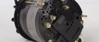
Relay block
It is mounted on a special reader and here the engine control relay and spark plugs can be located.
p, blockquote 26,0,0,0,0 —> p, blockquote 27,0,0,0,1 —>
That's all. And if you want to help supplement the material, then write in the comments.
Source
Replacing the lamp, removing the front turn signal
1. From the engine compartment, turning clockwise, remove the socket in the rubber case with the lamp. If necessary, replace the faulty lamp.
2. To remove the indicator, use a 10mm head to unscrew the two nuts securing it.
3. Remove the pointer
4. Install the front turn signal in the reverse order.
Before tightening the indicator fastening nuts, move it within the slot for the screws, achieving a uniform and minimal gap between it, the headlight and the hood
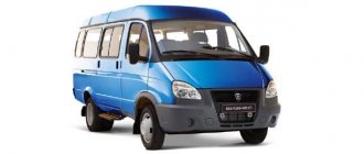
GAZ 3307 wiring diagram: features of the transition model
The fourth generation of the GAZ 3307 medium-tonnage truck was born in 1993 and completely replaced its predecessor, the GAZ 52/53, on the assembly line. As has been customary all these years, the car was largely unified with its platform, but it also had some differences that made it more modern.
Troubleshooting
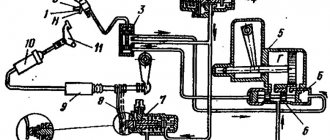
If any device fails, using an electrical circuit it is easy to check whether it has failed or whether the electrical circuit has been interrupted somewhere.
Power supply diagram for the GZ-3307 car
When checking, keep in mind that many circuits are energized only when the ignition is on. If the light is on or the tester arrow deviates, there is voltage at the contact, therefore, the element being tested has failed. If no current is supplied, you need to find an open circuit.
Ignition system Gas 3307
Connect its clamps to the ends of the wire being tested. If there is no break, the arrow will deviate, otherwise it will remain motionless. To restore the circuit, you can connect the necessary contacts with another wire, but you must route and secure it away from the moving parts of the car.
Features of GAZ 3307
This model was considered a transitional model, so the automaker did not consider it as an object for serious modification. The following was inherited from its predecessor:
- Chassis;
- Power unit;
- Body, including its cargo modifications;
- Basic controls.
New cabin
A new element of the GAZ 3307 car was a modern cabin. She was different:
- Angular tail of the hood and wings;
- New lighting technology;
- Interior decoration;
- Adjustable seats with seat belts.
In addition, thanks to the installation of a new cabin with increased functionality on the chassis, the electrical wiring of the GAZ 3307 was also modified. This was required by the appearance on the car:
- Efficient ventilation and heating systems;
- Power steering;
- New instrument panel.
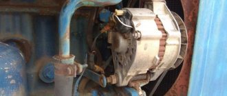
Electrical equipment
As for the electrical equipment, in connection with the manufacturer’s experiments trying to select the optimal power unit, the engine compartment wiring of the GAZ 3307 also underwent modernization.
- Instead of the previously used DC generator, the car received an alternating current generator model G250-G2;
- To protect the electrical equipment, a voltage regulator model 222.3702 was integrated.
Caution: Do not start the engine if the cable from the generator to the regulator is damaged, as well as checking for a spark. The electrical circuit is not designed for such loads, so it will fail during any attempt to start or test.
The ignition system has also undergone a slight modernization:
- Instead of the old B114-B ignition coil, a more powerful B116 was installed;
- The old distributor R133-B was replaced with a modernized 24.3706;
- An electronic ignition switch model TK102A appeared. Later, instead of it, the car was equipped with a universal switch 13.3734, as well as its modification - 13.3734-01;
- The circuit uses a resistor SE107, and on a number of models the universal 14.3729 was installed (see also the Gazelle wiring diagram).
Replacing the turn signal relay
Depending on the configuration, an electromagnetic relay-breaker of type RS-950P-T or an electronic breaker of type 494.3747, or 642.3747 can be installed on the vehicle
If the RS-950P-T relay fails, we recommend replacing the relay assembly, since if the winding is burned out or the contacts are badly burned, it is difficult to restore its functionality in a high-quality manner.
The design of relays type 494.3747 or 642.3747 is non-separable.
The turn signal breaker relay is installed on the bulkhead under the instrument panel on the left side.
Verification methods
Given the external similarity of the electrical equipment, the automaker reasonably assumed the possibility of errors when servicing the car independently, the price of which was high. Therefore, I provided automatic protection of elements from accidental short circuits:
- The generator excitation winding circuit is protected using a protection relay, as well as a separating diode;
- While the engine and generator are running, the relay contacts are open;
- If a wire breaks or short circuits, the current flowing through the relay winding will increase;
- The opposing winding will create a magnetic field, the core will retract and open the relay contacts (see also the VAZ 2101 wiring diagram).
To check the serviceability of the protection you must:
- Turn off the engine;
- Turn on the ignition;
- Connect the voltage of the relay-regulator to ground;
- Alternately press the anchors RN and P3, closing their contacts.
If the relay is working properly, the voltmeter needle will move to the “0” mark. If this does not happen, the transistor is faulty and the relay regulator must be replaced.
Description
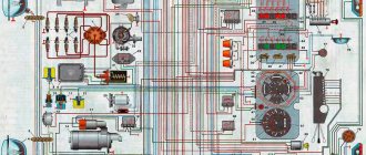
The electrical circuit of the GAZ-3307 is a drawing on which there are pictograms of the electrical elements of the car, connected to each other by switching lines indicating wires. The equipment is located approximately where it is when looking at the machine from above, although deviations (sometimes significant) are possible. On the left are usually the headlights and sidelights of the front of the car, to the right are the electrical equipment of the engine compartment, interior and rear lights.
Electrical circuits are available in black and white and color. The latter are easier to read; the colors of the lines are the same as those of the corresponding wires. Often electrical components are shown in the form of pictures (instrument panel, starter, headlights, etc.), they can be recognized without looking at the “legend” (the explanatory text under the diagram or on the side of it). An example of a color wiring diagram is shown below. Black and white diagrams are usually more detailed and often provide additional information (for example, thin lines show current conductors inside devices). The color of the wires is indicated by a letter (H - black, Z - green, and so on). The numbers (2; 0.5 and others) in the breaks in the switching lines indicate the cross-sectional area of the wire in square millimeters.
There are standard pictograms and conventional images of certain devices. Next to them (sometimes on a callout) is a number or letter with numbers. This is the designation of the element whose name is indicated in the “legend”.
Features of electrical wiring GAZ 3307 and GAZ 3309 diesel
The main difference between GAZ 3307 and GAZ 3309 is observed in the engine compartment. The latest production of diesel cars began to use power units produced by YaMZ and MMZ, equipped with electronic components with a CAN bus. Additionally, the circuit includes an anti-lock braking system.
The design features of the electrical system of the GAZ 3309 diesel truck include:
- The voltage in the on-board network is 24V, which ensures reliable starting of the power unit at low temperatures.
- Four batteries with a capacity of 55 A/h each are used to supply power. The devices are connected in pairs in parallel circuits, which are then crossed in series. When using a YaMZ diesel engine, two 110 A/h batteries are installed.
- The engine is equipped with a synchronous three-phase generator with an electromagnetic excitation principle. The device is equipped with a built-in rectifier unit and a voltage regulator with an adjusting screw. Switching the unit ensures the generator operates in winter and summer. When delivered from the factory, the screw is turned out all the way, i.e. it is in a condition for operation in the warm season.
The GAZ 3307 gasoline truck is based on the GAZ 53A model car, but has changes in the design of the electrical circuit:
- an alternating current generator with increased power is installed;
- an integrated relay-voltage regulator is used, ensuring stable operation;
- a modernized high-voltage pulse distributor and ignition coil were used;
- contactless ignition with a transistor switch has been introduced.
The general concept of the on-board network remains unchanged. The 12V DC source is the battery and the generator. The negative terminals of the devices are connected to the body or to the crankcases of the units.
Features of the electrical circuit are described in the operating manual supplied with each GAZ truck.
Replacing the lamp, removing the side turn signal
1. From the engine compartment, remove the socket with the lamp and the rubber cover from the turn signal by hand.
2. Remove the lamp from the socket.
3. Move the turn signal repeater back
4. Remove the turn signal
Install the side turn signal in the reverse order.
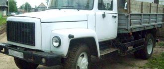
GAZ-3307
GAZ-3308 GAZ-3309
is a series of medium-duty trucks produced from 1989 to 2022 in various modifications and with various changes with both diesel and gasoline engines. In this article we will show a description of fuses and relays Gas 3307 3308 3309 with block diagrams and their locations.
p, blockquote 1,0,0,0,0 —>
p, blockquote 2,0,0,0,0 —>
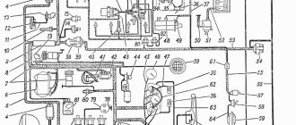
Wiring and electrical diagram of GAZ 3307
A detailed diagram of the electrical equipment of the GAZ 3307 in maximum equipment includes elements and components:
- Side turn signal mounted on the right front fender.
- Front marker light (right).
- Right headlight.
- Connection strip.
- Left headlight.
- Low beam lamp installed in the headlight.
- High beam lamp.
- Side light bulb.
- Front marker light (left).
- Direction indicator lamp installed in the front position lamp.
- Side turn signal located on the left front fender.
- Coil.
- Spark pulse distributor.
- Candle.
- An additional resistor to eliminate radio interference in the spark plug tip.
- Starter.
- Battery.
- Starter control relay.
- Battery power switch.
- Indicator lamp for activated high beam headlights.
- Upper section of the interior fuse box.
- Klaxon.
- Gas valve solenoid. Installed only on trucks equipped with gas cylinder equipment.
- Electromagnetic element of the gasoline supply valve, used on vehicles with a combined fuel system (gas-gasoline).
- Fuel type switch.
- Ignition system switch.
- An auxiliary relay that turns on the starter.
- Central lighting mode switch.
- Generator.
- Control key for rear fog lamp operation.
- Plug connector.
- Control resistance.
- Additional fuse for autonomous heater. The unit is installed as a separate order.
- An electric motor that ensures the functioning of an independent engine heating system.
- Instrument cluster illumination lamp.
- Cabin lighting.
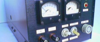
- Ammeter.
- Voltage regulator unit in the on-board network.
- Autonomous heater control panel.
- Fuel ignition switch in the heater boiler.
- Autonomous operating mode switch.
- An electromagnetic valve that regulates the supply of gasoline to the combustion chamber of an autonomous heater.
- Gas system pressure gauge.
- Coolant temperature sensor.
- Sensor for turning on a lamp warning of overheating of the power plant.
- A sensor that transmits information about the pressure in the lubrication system.
- A separate device that measures critically low pressure in oil lines.
- Ignition switch with built-in contact group.
- Bottom of the interior fuse box.
- A socket designed to connect additional equipment (portable lamp, etc.).
- Alarm control button.
- Starter heater spark plug.
- Second gas system pressure gauge.
- Gasoline level indicator in the fuel tank.
- A control device that displays engine temperature.
- Lubrication system pressure gauge.
- Electric motor to drive the windshield wiper blades.
- Control relay for the glass cleaning system.
- Washer pump drive motor.
- The steering column switch is responsible for selecting the operating modes of the headlights and direction indicators. Additionally, the device is used to provide warning sounds.
- Key for turning on increased fan speed for the standard cabin heating system.
- A similar unit for lower frequency.
- Brake light limit switch.
- Toggle switch for determining the fuel level in different tanks.
- Steering column switch for windshield wiper operating modes.
- A separate indicator displaying the operation of turn signals on towed equipment.
- Indicator lamp for direction indicators on the tractor. When using a single vehicle, only this lamp is active.
- Indicator for turning on side lighting.
- Indicator of the state of the drive of the second circuit of the brake system.
- A similar lamp for the first circuit.
- Indicator lamp for activation of the parking brake and malfunctions in the main circuits.
- Signal unit housing.
- Limit switch for determining the position of the parking brake handle.
- Heater motor on the right side of the cab.
- A similar unit for the left side.
- Measuring fluid level sensor in the hydraulic brake drive.
- A sensor that measures the degree of vacuum in the first brake circuit.
- A similar device for the second circuit.
- Sensor for measuring the amount of fuel in the main tank.
- Switch plate.
- Limit switch in the crankcase box, used to connect the reverse light.
- A contact relay that provides operation of the hazard warning lights and direction indicators.
- Fuel level measurement sensor in the additional tank.
- Back light.
- Socket for connecting electrical equipment on the trailer.
- Fog light mounted on the rear of the truck.
- Reverse lamp.
- Brake warning lamp.
- Dimensional signal.
- Rear direction indicator.
Color codes for wires in the diagram:
- B - white;
- K - red;
- F - yellow;
- Z - green;
- Kch - brown;
- Ch - black;
- G - blue;
- O - orange;
- P - pink;
- F - purple;
- C - gray.
The above diagram should be used with caution when repairing used GAZ 3307 trucks. Due to the low corrosion resistance of wiring, owners often replace entire sections with products with different insulation. As a result, difficulties arise during subsequent maintenance.
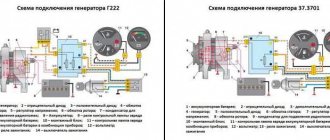
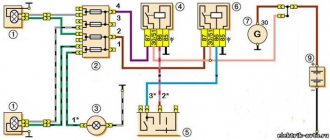
Connection diagram for generator and voltage regulator
The connection diagram for these nodes is no different from other cars. The circuit contains a relay and a separate wire to ensure the operation of the ammeter built into the instrument cluster. The photo shows the circuits connecting the generator to the battery via a discharge relay.
Schematic diagram of generator installation on GAZ 3307
Ignition system electrical circuit
The truck is equipped with a battery-based contactless ignition system with a transistor switch, consisting of the following components:
- coils;
- pulse distributor;
- individual candles;
- connecting wires.
Repair and Improvement" on DRIVE2
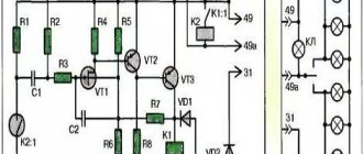
Based on the operating experience of VAZ (first the classic 21011, then 2111), it has long been noticed that very often the ignition switch contacts (ISC) that control the starter solenoid relay burn out and become unusable. The current through these contacts reaches 20A. We have to replace the entire contact group. So I decided to fix this problem immediately on a new machine, without waiting for it to appear. A common option is to install an additional relay in the power circuit and control it with 3Z contacts. Everything is simple, but as it turned out, this is not at all necessary, since you can use an existing starter blocking relay, retaining its previous functions completely. As shown by the analysis of the circuit, the starter blocking relay is powered from + 12V from the main relay of the ECU, and the minus is supplied from pin 50 of the ECU (January 7.2), and is controlled by the “open collector” key in the ECU. When the ignition is turned on, the ECU sets the “low level” (shorts to ground) on contact 86 of the locking relay. The relay is activated, completing the circuit between the ignition switch and the starter solenoid relay. When you turn the key ZZ from pin “50”, 12V is supplied to the starter solenoid relay. As soon as the engine starts, the ECU removes the signal from pin 88 of the relay, it is de-energized, breaking the circuit, and thereby blocking the starter. The blocking works! Fig. 1 shows a fragment of the circuit in the basic version, and Fig. 2 - after modification. As you can see, the changes are minimal: 1. The pink-black wire is disconnected from the pin. "85" and isolated; 2. The power wire from the ignition switch is connected to pin. “85” relay 3. Added a power wire (30 cm) from the connector from which the CB is powered (2-pin connector to the front harness) - with a cross-section of at least 4 mm2, connected to the pin. 87 relays. Now the power circuit is controlled through a relay, and the current through the 3Z contacts does not exceed 0.2A. The modification was completed in 2009. Pros: minimal alterations, no need for another relay, saving space in the control unit Cons: not found in 6 years.
Below is a fragment of the diagram.
But that's not all! The next weak point: the power contacts of the starter solenoid relay. Due to high currents, they receive an even greater electrical load, and as a result, erosion. You can protect them from sparking, especially when opening, by connecting one powerful diode in parallel with the starter and the control winding of the solenoid relay. The essence of the modification is to suppress the “self-induction emf” - the main cause of burnt contacts and the source of parasitic surges in the on-board network. Diodes were used quite common, KD2998 - large pulsed and direct current, and they were on hand in sufficient quantities. You can use rectifier diodes from computer power supplies rated for a forward current of at least 30A. The diodes are placed in 2 layers of heat shrink and connected directly to the starter on short wires. The connection diagram is shown.
Electrical wiring and equipment diagrams for GAZ 3309
The equipment of diesel trucks includes:
| Number on the diagram | Item Description |
| A8 | Engine pre-heater unit, installed as a separate order |
| A10 | Heater |
| IN 1 | Oil operating pressure meter |
| AT 2 | Extremely low oil pressure alarm |
| AT 7 | Measuring element in the engine cooling system |
| AT 8 | A special element designed to signal engine overheating |
| AT 12 | Measuring element in the fuel tank |
| B19 | Air filter cavity clogging sensor |
| B31 | Emergency pressure sensor in the primary circuit of the brake system |
| B32 | A similar element in the second circuit |
| B61 | Preheater overheat indicator |
| B67 | Fluid level sensor in hydraulic brake drive |
| B97 | Primary circuit pressure measuring device |
| B98 | Similar detail of the second circuit |
| B99 | Measuring device for the emergency condition of the piston stroke in the pneumatic brake booster (primary circuit) |
| B100 | A similar part in the second circuit (right side) |
| B101 | A similar part in the second circuit (left side) |
| D25 | Controller for electric headlight angle adjustment |
| E1 | Left headlight |
| E2 | Right headlight |
| E5 | Left front combination light (side light and turn signal) |
| E6 | Similar element on the right |
| E9 | Turn direction repeater mounted on the surface of the right wing |
| E10 | Identical unit on the left wing |
| E11 | Contour lighting lamp on the cab roof (left side) |
| E12 | A similar detail on the right side of the cabin |
| E16 | Cabin interior lighting |
| E27 | Tail light on the left side of the truck |
| E28 | A similar unit on the starboard side |
| E29 | Reverse indicator light |
| E31 | Rear fog light |
| E33 | Left rear contour light |
| E34 | Similar detail on the starboard side |
| E35 | Engine compartment lighting lamp |
| E37 | Front left side signal |
| E38 | Right side marker light on the front |
| E39 | Side marker to indicate the rear left side of a truck |
| E40 | Identical element on starboard side |
| E50-E53 | Individual glow plugs (4 pcs.) |
| E54 | Starter plug used when igniting an autonomous heater |
| E73 | Left indicator light module |
| E84 | Similar element on the right side |
| F26 | Thermal fuse to protect the preheater |
| F41 | Power fuse module in the engine compartment |
| F42 | Upper section of the cabin fuse block |
| F43 | Similar bottom part |
| G1 | Generator |
| G2-G5 | Batteries (4 pcs.) |
| H1 | Left horn |
| H2 | Right beep |
| H3 | Buzzer signaling a drop in air pressure in the pneumatic system |
| H7 | Low engine oil pressure warning light |
| H8 | Power unit overheat indicator |
| H9 | Light warning signal for overheating of the autonomous heater |
| H11 | Air filter clogged with dust lamp |
| H16 | Display of direction indicator operation (on base chassis) |
| H19 | Indicator of emergency fuel remaining in the tank |
| H20 | Displaying the operating mode of headlights with high beam |
| H30 | Parking brake warning light |
| H37 | On-board pre-heater operation indicator |
| H39 | Signal of a breakdown of the standard ABS system in the brake drive |
| H44 | Separate lamp for illuminating the pressure indicator in the primary circuit of the brake system |
| H45 | A similar device for the secondary circuit device |
| H47 | Illumination lamp for displaying the fuel level in the tank |
| H48 | Ammeter illumination in instrument cluster |
| H54 | Voltage drop indicator at battery terminals |
| H56 | Low Brake Fluid Level Warning Light |
| H62 | Signal lamp on the front of the truck |
| H66 | Speedometer dial illumination system |
| H67 | Lighting of the instrument displaying engine temperature |
| H68 | A similar device for illuminating the oil system pressure gauge |
| H69 | Tachometer light |
| H74 | Lamp in the rear light warning of the start of braking |
| H76 | Signal lamp on the rear of the machine |
| H78 | Turn signal lamp (on rear of truck) |
| H80 | Indicator for turning on external side lighting |
| H96 | Pre-heater spark plug warning light |
| H98 | Low beam filament |
| H100 | High beam lamp filament |
| H102 | Direction indicator lamp (in front lamp) |