- home
- Media center
- Articles
- Winch ZIL-131. Specifications
Menu
- News
- Articles
- Video materials
- Photo materials
- Publication in the media
- 3D tour
30.12.2020
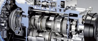
ZIL-131 refers to trucks with high cross-country ability. The development of the model was carried out simultaneously with the previous version of the ZIL-130. Today it continues to be actively used due to a set of significant advantages in comparison with similar vehicles. It has a simple design, has a high degree of reliability, and does not require expensive maintenance.
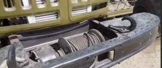
The ZIL-131 winch is designed to organize independent pulling of a truck while passing through difficult-to-pass locations. In addition, it will provide effective assistance to other cars stuck on the road. Present in two models 131H and 431411.
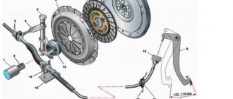
Winch for GAZ 66
The main task of the winch on the GAZ 66, like any other automobile winch, is self-pulling, and for many modifications of this model, they were installed standard with a mechanical drive.
Preference was given to mechanics due to the reliability of the components and the almost complete absence of breakdowns. The only part that is highly vulnerable is the cable. But if you do not exceed the maximum permissible load by more than twice, it will last a long time without breaking. An important advantage of the winch on the GAZ-66 (colloquially shishiga) is its high moisture and dirt resistance - it is capable of continuous operation in various weather conditions.
Technical characteristics of a standard mechanical winch for Gas 66
- Maximum load - 4500 kg (provided the cable is completely unwound)
- Traction force - 3000 kg (rope in coiled state)
- Gear ratio - 1:24
- Rope dimensions - Length 50 m, Diameter Ø ± 14 mm
- Mechanical drive (from power take-off)
- Control by lever inside the driver's cab
- Winch weight - 120 kg
The device is installed on the front of the car frame. The winch is driven by a power take-off (PTO), mounted on the transfer case, through a driveshaft and axle.
It should be noted that such a winch can be mounted not only on the “sixty-sixth”. In this configuration and without modifications, it can be mounted in a horizontal position on the following models: GAZ3309, 3308 “Sadko”.
The very principle of operation of the winch is almost no different from similar mechanical devices. Winding and unwinding of the cable occurs exclusively while the car engine is running. An important advantage over the electrical circuit is the speed of operation (it is an order of magnitude higher).
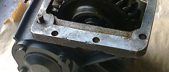
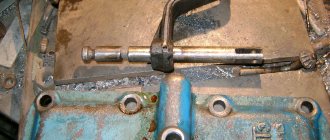
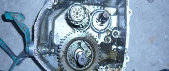
Rice.
1. Winch: 1. 6, 13 - oilers; 2 — thrust ring of the coupling; 3 — drum engagement clutch; 4 — drum activation fork; 5 — front cross member; 7 — safety bracket; S—cable guide roller; 9 — cable guide; 10 — winch cable with hook; 11 — winch gearbox; 12 - drum; 14 — nut of the cable fastening bracket; 15 — winch drive drive shaft; 16 — power take-off lever; 17 — power take-off; 18 — drum brake shoe; 19 — drum fork finger; 20 - cross member; 21 — traverse; 22 - drum shaft bearing The drum shaft rotates on three bronze bushings (bearings), two of which are installed in the gearbox housing and one in the traverse. The cross member and gearbox housing are bolted to the cross members. The front cross member is attached to the buffer, the rear cross member is attached to the frame cross member.
The drum shaft bearing in the traverse is lubricated through an oiler, and the drum rotation surface along the shaft is lubricated through two oilers located at the ends of the drum. The drum shaft bearings installed in the gearbox housing are lubricated with oil poured into the gearbox and thrown out by the worm wheel during operation.
The winch cable is steel, non-unwinding, with a metal or hemp core. At the free end of the cable there is a hook connected to the cable through a thimble.
The winch gearbox is assembled in a cast-iron split housing and consists of a single-throw steel worm of a globoid gear and a worm wheel with a bronze crown, a drum shaft, an automatic brake mechanism, bushings, bearings and their covers. The worm gear of the gearbox is mounted on the drum shaft on two keys and secured against axial movements with a pin. The drum shaft with the worm wheel is fixed in the axial direction by a washer installed between the end of the gearbox housing and the end of the groove in the cover. The washer is attached to the end of the shaft with two bolts secured with wire. The hole in the crankcase is closed with a lid. On the opposite side, where the shaft exits the gearbox, there is a cover with a cuff that seals the shaft to prevent oil leakage.
The upper half of the crankcase has an inspection hatch covered with a lid.
The globoid gear worm is mounted on two tapered roller bearings. The front bearing is covered with a cover with shims, the cover is tightened with bolts.
At the rear end of the worm shaft there is a drum for the automatic brake mechanism and a flange for mounting the propeller shaft. The brake drum is mounted on a key, and the flange is mounted on splines. These parts are tightened to the bearing with a nut and washer, the nut is pierced into the groove of the shaft. The brake drum is covered with a cover that simultaneously presses the tapered bearing. Adjusting shims are placed under the end of the cover, and a cuff is also placed in the cover to prevent oil leakage from the gearbox. The end of the drum cover is closed with a stamped cover, in which a seal is installed that protects the brake mechanism from dirt. An O-ring made of copper or paronite is installed between the end of the inner ring of the bearing and the end of the brake drum hub.
The drum is braked by a brake band with a friction lining. One end of the brake mechanism band is rigidly fixed in the wall of the cover, and the other is spring-loaded. The spring tightens the tape in the direction opposite to the rotation of the worm shaft when winding the winch cable. The tape, under the influence of friction, compresses the spring, which leads to a weakening of the pressure of the tape on the drum, i.e.; reduces braking. Due to the rigid fastening of the opposite end of the tape during reverse rotation under the influence of friction, the tape self-tightens, causing the worm to slow down.
At a low rotation speed of the worm shaft, the braking force created by the automatic brake mechanism is insignificant and does not prevent the cable from unwinding. If the safety pin is cut off during overload, when the winch drum begins to rotate in the opposite direction at an increased speed, the effect of the braking mechanism becomes significant and serves as an addition to the self-braking action of the worm gear, which prevents rapid rotation of the winch drum and unwinding of the cable. The tension of the brake band is adjusted with a nut. When screwing the nut (rotating clockwise), the spring pressure increases. The brake mechanism must be adjusted so that when the cable unwinds, the brake drum does not overheat.
The winch cable guides are bolted to the lower flanges of the front buffer and the rear cross member of the winch. At the front, between the guides, there is a cable guide roller and a rod that keeps the cable from falling out. The roller rotates on an axis secured with nuts in the guides. The roller bearings are lubricated through a grease nipple installed at the left end of the roller axis.
Torque from the power take-off to the winch gearbox is transmitted by a cardan drive. The cardan shaft is tubular with ends welded at both ends. A fork is installed on the front cylindrical tip, secured with a safety pin. A sliding fork is installed on the rear spline end. The universal joint crosspieces are placed in forks on needle bearings. The needle bearings are fixed in the forks with retaining rings and sealed. The bearings are lubricated through a grease nipple in the crosspiece.
On cars produced before 1979, the cardan transmission consisted of two shafts - front and rear. The front driveshaft was made of a single rod and had an intermediate support, and the rear shaft was tubular. The cardan transmission had three hinges.
The set of accessories for a car with a winch includes a winch block (pulley hoist), which is used if necessary to increase the traction force of the winch or change the direction of traction, and a cable for attaching the block.
When the vehicle is moving, the winch cable must be completely tightly wound around the drum, and the drum must be connected to the shaft with a coupling. It is only possible to disconnect the drum from the shaft when unwinding the cable manually.
To engage the winch, you need to press the clutch pedal, engage a gear in the power take-off and release the clutch pedal. The cable should be wound in the winding gear, and the free cable should be unwinded manually, without turning on the gears, but turning off the drum clutch. In some cases, you can engage gear to unwind the cable.
To pull the car out yourself, you need to unwind the cable, hook it to some stationary object (tree, stump, pole, etc.), turn on the cable winding gear in the power take-off box and tighten the cable at a frequency of 14 ... 16 min-1 rotation of the drum shaft winches (1000 ... 1100 min-1 engine crankshaft). When self-pulling the vehicle on wet turf roads, it is allowed to engage the drive axles in first gear of the gearbox.
When winching another vehicle, place the gear shift lever in the neutral position and brake the vehicle. After pulling out, you need to stop the winch by disengaging the clutch and put the power take-off gear shift lever in the neutral position. To loosen the cable, you need to place the power take-off gear shift lever in the cable unwind position. To secure the cable in the driving position, it is necessary to hook the cable hook to the front towing hook, turn on the cable winding gear in the power take-off, and smoothly pull it. After this, place the power take-off gear shift lever in the neutral position.
In the case of using a winch using a block (pulley hoist) to increase the traction force when pulling the car out by itself, the block must be secured to an object selected as a support, and the winch cable hook to one of the front tow hooks of the vehicle. If the block is used to change the direction of traction when pulling out another car, it is secured to a supporting object, and the hook of the cable is secured to the towing hook of the vehicle being pulled out. When using a block to increase the traction force when pulling out another car, it is attached to the hook of this car, and the hook of the cable is attached to an object that serves as a support.
When using the winch, the following rules must be observed. 1. The pulling force on the cable should not exceed 45 kN. To obtain more force, you need to use a block. 2. The working length of the cable should not exceed 65 m, the rest of the cable (at least three to four turns) should remain wound on the drum. 3. The maximum permissible oil temperature in the gearbox during winch operation is 130 °C. 4. The cable must be unwinded manually. It is allowed to engage the gear to unwind the cable, but you must manually tighten the cable. 5. The angle of the cable relative to the axis of the car (in the horizontal plane) should not exceed 15°; at these angles, the length of the pull-up cable should be no more than 10 ... 12 m. For larger angles, use a block.
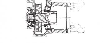
Rice. 2. Schemes for using a winch using a block (pulley hoist): 1 - block; 2 - stationary object
It is strictly prohibited: 1) to use a winch cable to tow a car; 2) engage the vehicle in reverse gear while the winch is operating; 3) change gears while pulling the car under a heavy load and when the car is moving back down the mountain; 4) be near the cable, direct the laying of turns of the cable while the winch is operating; 5) place a bolt or other parts in the hole of the cardan joint fork instead of a special safety pin; 6) allow the vehicle to move with the winch drum disconnected from the shaft.
In case of incorrect laying of the rope turns on the drum and malfunction of the mechanisms, the winch should be stopped. To stop the winch, you must first disengage the clutch, and then disengage the gear in the power take-off. If excessive heating of the oil in the gearbox is detected, as evidenced by excessive steam formation, the winch should be stopped to cool the oil and the cause of the heating should be determined.
When disassembling the gearbox, it is prohibited to remove the drum of the winch worm brake mechanism by screwing the bolts all the way into the cuff. This leads to destruction of the cuff and its failure. To ensure that the bolts do not rest against the cuff, screw the bolts in 7 ... 8 mm, hook the puller onto the bolts and remove the drum.
Maintenance
Maintenance of the winch consists of checking and tightening all fastening parts, lubricating the bearings, adding or changing oil in the gearbox, checking the quality of the seals, adjusting the bearings, checking and adjusting the axial clearance of the drum shaft, and adjusting the worm gear engagement.
The winch gear housing is filled with oil through the hatch in the upper part of the gearbox to the level of the control hole. After 15...20 pull-ups, you need to check the oil level. If necessary, add oil up to the inspection hole. TM-3 - 18 oil is used (TSp-15K or TAP-15V as a substitute). The oil needs to be changed once a year (in the fall) in CO. The oil is drained through the drain hole in the lower part of the crankcase.
Cardan joints, splined connection of the drive shaft, drum shaft, outer shaft bearing, axis of the fork, and drum clutch are lubricated with grease during TO-2.
When axial play of the worm appears or when replacing the worm pair, it is necessary to adjust the tapered roller bearings. First of all, when axial movement of the worm shaft is detected, the bolts securing the bearing caps should be tightened. If the gap does not disappear, adjustment must be made.
Tapered roller bearings should be preloaded. The turning torque of the worm shaft should be 0.2 ... 0.6 Nm. The worm bearings are adjusted by changing the number of shims under the covers. If the worm shaft rotates freely, then it is necessary to remove gaskets of equal thickness from under both covers. If more than the specified torque is required to rotate the shaft, shims of the same thickness should be added under both covers. When adjusting the bearings, the worm wheel with shaft and drum, flange, and brake drum must be removed. The difference in the thickness of the adjusting shims under the covers should be no more than 0.1 mm. It is necessary to change the thickness of the gaskets under the covers when adjusting the engagement of the worm pair along the contact patch.
As the ends of the gearbox housing or the thrust washer wear, the axial clearance of the drum shaft and the displacement of the engagement contact patch increase. In this case, the engagement of the worm pair is disrupted and the wear of the teeth increases, and the rim of the worm wheel may be destroyed.
The position of the engagement contact patch must be periodically checked and adjusted. The contact patch is checked “for paint” by the stain on the wheel teeth. The position of the contact patch is adjusted after completing the adjustment of the worm shaft bearings. The symmetrical axial location of the contact patch is adjusted by corresponding movement of the drum shaft with the worm wheel in the direction opposite to the displacement of the contact patch. .To do this, it is necessary to remove or install gaskets under the end of the thrust washer attached to the shaft or replace it.
The drum shaft with the worm wheel should rotate freely after adjusting the gearing, but the permissible axial play should be no more than 0.1 mm. The axial clearance is measured at the end of the drum shaft when the wheel moves in the axial direction. The thrust washer must be bolted to the shaft and closed with a cover.
The contact patch along the tooth height is adjusted by moving the worm relative to the worm wheel. To do this, it is necessary to move part of the shims from under the cover of one bearing to the cover of the other, without changing the adjusted preload of the bearings.
The worm gear only works reliably if it is properly engaged. Incorrect adjustment of the contact patch and bearing preload causes increased heating of the gearbox during operation.
Peculiarities
Based on the universal chassis of the specified truck, various modifications of special vehicles were produced. Among them:
- Fire trucks.
- Fuel trucks and fuel tankers.
- Oil refillers.
- Tank trucks.
- Airfield tractors with increased weight.
For military laboratories, workshops, radio stations, and headquarters versions, standard universal, sealed bodies were used. They were equipped with special filtration systems that take air masses from outside and supply them to the van, while simultaneously disinfecting the interior.
KUNG from ZIL 131, dimensions and weight:
- length - 4.8 m;
- height - 1.95 m;
- width - 2.2 m;
- weight (dry/curb) - 1.5/1.8 t.
As many years of practice have shown, the ZIL 131 has proven itself to be a reliable, durable and easy-to-maintain truck. Its main advantage is its high cross-country ability, which guarantees passage with a full load of washed-out and clayey areas. An additional bonus is the presence of a reduction gear, and mechanical tire inflation allows you to adjust the tire pressure, depending on the road surface and axle load.
In addition, drivers note a relatively comfortable cabin and easy access to main parts, which increases the machine’s maintainability. Despite the fact that the serial production of this vehicle was completed many years ago, it can still be found in various sectors of the economy.
Truck Features
The organ that allows you to use it is located on the dashboard inside the cabin and is a regular metal two-position toggle switch.
Also, the front axle could be turned on using the gear shift lever.
The ZIL-131 gearbox is mechanical in its technical characteristics.
The second and third gears are equipped with special locks. They prevent the speed from being switched off inadvertently if the load on the engine increases rapidly. This is extremely important during a long climb.
For its year of production, the ZIL-131 is equipped with quite advanced electronics.
The design uses an alternator with a large power reserve, as well as contactless ignition with an electronic switching device.
In addition, there is a special vibration device that ensures movement for 30 hours without stopping on its own. All this was new for those years when the car in question began to be mass produced.
Characteristics and weight of the ZIL 131 car
Parameters of the truck in question:
- length/width/height (mm) - 7040/2500/2510;
- wheelbase (mm) - 3350/1250;
- ground clearance (under the front axle/in the area of intermediate and rear drive) (mm) - 330/355;
- wheel track front and rear (mm) - 1820;
- minimum turning radius (mm) - 1002;
- tires - 12.00/20;
- cargo platform dimensions (mm) - 3600/2320/569;
- loading height (mm) - 1430;
- weight of empty ZIL 131 (curb) (kg) - 5275 (6135);
- load capacity indicator (on highway/dirt road) (t) - 5.0/3.5;
- total weight of the truck with winch (kg) - 10425.
The load on the road from the mass of the vehicle is distributed as follows: front axle - 2750/3045 kgf, rear bogie - 3385/3330 kgf.
Winch weight zil 131
Vehicle modification:
— ZIL-131NA — a vehicle with unshielded and unsealed electrical equipment; — ZIL-131NS and ZIL-131NAS — HL version for cold climates (up to minus 60°C).
Upon request, ZIL-131N vehicles can be produced as a chassis without a platform for mounting various bodies and installations.
From 1966 to 1986 The ZIL-131 car was produced.
Load capacity: on all types of roads and terrain 3750 kg. on asphalt concrete roads (without trailer) 5000 kg.
Equipment weight (without winch) 6135 kg. Including: front axle 2750 kg. per trolley 3385 kg.
Gross weight 10185 kg. Including: front axle 3060 kg. per trolley 7125 kg.
Permissible total trailer weight with a vehicle load weight of 3750 kg: for all types of roads and terrain 4150 kg. on roads with asphalt concrete surface 6500 kg.
The figures below are given for a vehicle with a gross weight of 10,185 kg and a road train with a trailer with a gross weight of 4,150 kg.
Max, vehicle speed is 85 km/h. The same, road trains 75 km/h.
Acceleration time of the car to 60 km/h is 50 s. The same, road trains 80 s.
Vehicle run-out from 50 km/h is 450 m.
Max. climbability by car 60% Same, by road train 36%
The braking distance of a car from 50 km/h is 25 m. The same, for a road train 25.5 m.
Control fuel consumption, l/100 km, at a speed of 60 km/h: car 35.0 l. road trains 46.7 l.
Depth of fording with a hard bottom at nominal air pressure in mud: without preparation 0.9 m. With preliminary preparation (ZIL-13 1N vehicle) lasting no more than 20 minutes 1.4 m.
Turning radius: on the outer wheel 10.2 m. overall 10.8 m.
Engine.
Mod.ZIL-5081. For basic data, see car ZIL-431410. To heat the engine, a P-16B heater with a heating capacity of 15600 kcal/h is installed on the car.
Transmission.
The clutch is sealed, single-disk, with peripheral springs and a damper, the drive is mechanical. Gearbox - data see Vehicle ZIL-431410, additionally equipped with a ventilation system for fording. Transfer case - Two-stage, with front axle clutch, gear. numbers: I-2.08; II-1.0. Gear shift - lever; The front axle drive is electro-pneumatic. Power take-off from the transfer case - UP TO 44 kW (60 hp). The cardan transmission consists of four cardan shafts: gearbox - transfer case, transfer case - front axle, transfer case - middle axle, middle axle - rear axle. The main gear of the drive axles is double with a pair of bevel gears with spiral teeth and a pair of spur gears with helical teeth. The gear ratio is 7.339. The front axle has constant velocity joints.
Wheels and tires.
Wheels - disc, rim 228G-508, fastening - with 8 studs. Tires - with adjustable pressure 12.00 - 20 (320 - 508) mod. M-93 or 12.00R20 (320R508) mod. KI-113. Air pressure in tires with a weight of transported cargo of 3750 kg: nominal - 3 kgf/cm. sq., minimum - 0.5 kgf/cm. sq.; with a weight of transported cargo of 5000 kg - 4.2 kgf/cm. sq.
Suspension.
Dependent; front - on two semi-elliptic springs with rear sliding ends and shock absorbers; the rear is balanced on two semi-elliptical springs with six reaction rods, the ends of the springs are sliding.
Brakes.
The working brake system is with drum mechanisms (diameter 420 mm, lining width 100 mm, cam release), single-circuit (without separation along the axes) pneumatic drive. The parking and spare drum brake is installed on the secondary row of the transfer case. The drive is mechanical. The trailer brake drive is single-wire.
Steering.
The steering mechanism is a screw with a ball nut and a piston-rack that engages with the toothed sector of the bipod shaft, with a built-in hydraulic booster, transmission. number 20, oil pressure in the amplifier 65-75 kgf/cm.
Electrical equipment.
Voltage 12 V, ac. battery - 6ST-90EM, generator - G287-B with voltage regulator PP132-A, starter - ST2-A, ignition system - "Iskra", shielded, contactless transistor.
Winch.
Drum type, with a worm gearbox, driven by a cardan shaft from a power take-off mounted on the gearbox, Maximum traction force - 5000 kgf, working cable length - 65 m.
Filling volumes and recommended operating materials.
Fuel tanks 2x 170 l, gasoline A-76; cooling system - 29l; engine lubrication system - 9l, all-season up to minus 30°C - oils M-6/10V (DV-ASZp-YuV) and M-8V, at temperatures below minus 30°C oil ASZp-6 (M-4/6V); power steering - 3.2 l, all-season oil grade P; gearbox (without power take-off) - 5.1 l, all-season oil TSp-15K, at temperatures below minus 30°C oil TSp-10; transfer case - 3.3 l, see gearbox oil; final drive housings for drive axles 3×5.0 l, see gearbox oils; winch gearbox housing - 2.4 l, see gearbox oil; shock absorbers - 2×0.45 l, liquid AZh-12T.
Weight of units
(in kg): Power unit assembly - 650; gearbox - 100; transfer case - 115; drive axles: front - 480, middle and rear - 430 each; frame with buffers and towing device - 460; springs: front - 54, rear - 63; wheel and tire assembly - 135; winch with cable - 175; cabin - 290; tail (facing, wings, mudguards, running boards) - 110; platform (without arches and awning) - 720.