Modern tractors are equipment capable of performing a wide range of work, including: tillage and other agricultural activities, road repair and construction work, maintenance of industrial and agricultural enterprises. The functionality of the tractor is expanded with the help of mounted and semi-mounted equipment, the stable and efficient operation of which is ensured by a properly selected hydraulic system. If the hydraulics installed at the manufacturer do not provide the required performance characteristics, then they are improved or a new one is installed.
Design of the hydraulic system of MTZ tractors
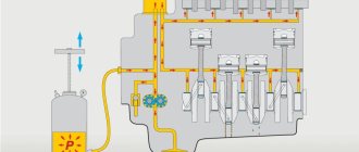
The hydraulic system is a set of mechanisms that transmit energy from the engine to the actuators. The standard separate-unit hydraulic system of MTZ tractors contains the following structural elements:
- tractor hydraulic pump – provides pressure for the flow of working fluid (oil), is attached to the body with studs (the most common are one- and two-section gear pumps of the NSh type);
- an intermediate gear with which the drive is connected to the pump unit;
- pump activation mechanism;
- oil tank;
- a filter that protects the hydraulic system from reduced efficiency and premature failure;
- hydraulic pipelines;
- hydraulic distributor;
- tractor hydraulic cylinder – responsible for the functionality of semi-mounted and mounted mechanisms;
- coolers, bends, valves, couplings.
In MTZ technology, two types of power cylinders are used. The main cylinder has an internal bore diameter of 100 mm. 2 remote cylinders equipped with retarding valves have an internal diameter of 75 mm. The main cylinder controls the rear linkage, and additional external cylinders control trailed or mounted mechanisms.
Design of the tractor hydraulic system - hydraulic pumps, distributors, hydraulic cylinders, pumps nsh
Separate hydraulic system (design, description and principle of operation)
The hydraulic system serves to transform and transmit the energy of the tractor engine to various executive units for the purpose of:
- control of mounted machine
- control of a trailed machine through hydraulic cylinders installed on it
- driving the working parts of mounted or trailed machines through the hydraulic power take-off system of the tractor
- performing automatic coupling with mounted and trailed machines
- changes and automatic support of the selected tillage depth
- adjusting the vertical reaction of the soil to the tractor propulsion, performing auxiliary operations on servicing the tractor (changing the base, changing the track, raising the frame, etc.)
Currently, a separate-aggregate type hydraulic system is widely used.
The unified separate hydraulic mounted tractor system (Fig. 10.3) includes:
- pump with drive and activation mechanism
- oil tank
- filter
- steel pipelines
- spool-type distributor with control mechanism
- elastic sleeves
- shut-off and quick connect couplings
- main hydraulic cylinder
- as well as - flow fittings, retarding valve and sealing devices
The hydraulic systems of some tractors have a hydraulic adhesion weight increaser with a hydraulic accumulator, a power regulator or a system for automatic control of tillage depth (SARG), and a hydraulic power take-off system (HPS).
The hydraulic system is designed in such a way as to ensure the widest possible operation of the executive link - a double-acting hydraulic cylinder (or several hydraulic cylinders with independent control).
A hydraulic cylinder can have four main states: movement of the piston in one direction, movement of the piston in the other direction, fixation of the piston by blocking the oil inlet and outlet of the hydraulic cylinder, the possibility of free movement of the piston in both directions from external force by connecting both cavities of the hydraulic cylinder to each other and with drain line. The distributor, which receives a flow of oil under pressure from the pump, provides one of four options for the operation of the hydraulic cylinder. In this case, the distributor has one spool with axial movement to one of four positions.
To protect the hydraulic system from excessive pressure increases, the distributor is equipped with a safety valve adjusted to a pressure of no higher than 20.5 MPa.
The hydraulic pump is the most critical element of the hydraulic system. The efficiency of the hydraulic drive largely depends on it. The most widespread are gear pumps of the NSh type, one or two sections. In heavy agricultural and industrial tractors, axial piston pumps of both adjustable and unregulated types are also used.
The pump takes oil through the suction line from the tank, the capacity of which should be 0.5 - 0.8 minute pump output. Oil purification is carried out using a strainer or a filter with a replaceable filter element, which ensures the removal of foreign particles with a size of 25 microns for fluid supplied from gear pumps and mechanically controlled distributors, and from 10 microns for piston pumps and electro-hydraulic distributors/
Let's consider specific typical designs of hydraulic system components.
Each pump model has a specific alphanumeric designation that characterizes its technical data.
So the designation NSh 32 U-3-L is deciphered as follows:
NSh - gear pump
32 the volume of working fluids in cm3 displaced from the pump per shaft revolution (theoretical flow);
U - unified design;
3 - design group characterizing the nominal pump discharge pressure: 2 - 14 MPa; 3 - 16 MPa; 4 - 20 MPa;
L - left direction of rotation of the pump drive. If the pump is in the right direction of rotation, then there is no corresponding letter in the designation.
Let's consider the design of a gear hydraulic pump and its drive.
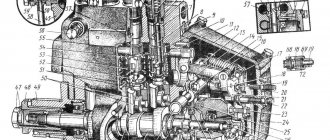
On tractors MTZ 100, MTZ 102, a pump NSh 32-3 of right rotation is used (Fig. 10.4). Oil is pumped into the pump using the drive 2 and driven 3 gears located between the bearing 1 and clamp 5 races and plates 4. The bearing race 1 serves a single support for the gear journals. Pressure ring 5 under oil pressure in the cuff cavity (not shown in the figure, located in the area of the discharge hole) is pressed against the outer surface of the gear teeth, providing the required gap between the teeth and the sealing surface of the race.
The plates 4, under oil pressure in the cavity of the end seals 16 and 14, are pressed against the gears 2 and 3, compacting them along the side surfaces in the high-pressure zone. The shaft of the drive gear 2 in the housing is sealed with two cuffs 19. The centering of the drive shaft of gear 2 relative to the mounting collar of the housing is ensured by a sleeve 20. The housing connector with the cover is sealed using a rubber O-ring.
Rice. 10.4 Oil pump NSh-32-3
1 — bearing race; 2 - drive gear; 3 - driven gear; 4 - platik; 5 — clamping clip; 6.10 — ball bearings; 7 - shaft; 8 - gear; 9 — body; 11 - fork; 12 — control roller; 13 — intermediate gear; 14 - cuff; 15 — washer; 16 — cuff; 17 — bearing cup; 18 — hairpin; 19 — cuff; 20 — centering sleeve
The pump is secured with four studs 18 on the housing 9 of the hydraulic units through a glass 17, in which it is centered by the housing seating belt. The splined shank of drive gear 2 of the pump fits into the internal splines of shaft 7, mounted on bearings 6 and 10.
When the engine is running, rotation through the independent PTO drive gears and intermediate gear 13 is transmitted to gear 8 (in the on position), which through the splines transmits rotation to shaft 7 and drive gear 2.
Gear 8 is moved by a manual control mechanism through a roller 12 with a fork 11 attached to it and can be fixed by the control handle in two positions: the drive is on, when gear 8 is out of mesh with gear 13. Switching on or off depending on the need for a hydraulic drive during MTA operation
Distributors of the tractor mounted hydraulic system are used to distribute the flow of working fluid between consumers, to automatically switch the system to idle mode (bypassing the working fluid into the tank) during periods when all consumers are turned off, and to limit the pressure in the hydraulic system during overloads.
On agricultural tractors, monoblock three-spool, four-position distributors with manual control are most widely used. On industrial tractors, monoblock one, two or three spool and usually three-position distributors with manual and remote control are used.
Tractor distributors have an alphanumeric designation such as P80 3/1-222, P80 3/2-222, P160 3/1-222 - Here the letter P means distributor; the first two digits of the letter are the maximum pump capacity, l/min, with which the distributor can operate; the remaining numbers and letters are the design version of the distributor.
A typical three-spool four-position valve is shown in Fig. 10.5
In housing 1 with channels 2, spool valves 3, bypass 7 and safety valve 11 are installed. Two covers are screwed to the housing. In the top cover 4 there are hinged handles for controlling the spools. The bottom cover 10 has a cavity for draining oil into the tank. Oil from the pump is supplied to the distributor through a pipeline. From the distributor, oil can flow through six pipelines into the piston and rod cavities of hydraulic cylinders. The bypass valve 11 is connected by a channel 6 with the cavity above the bypass valve. If the pressure in the system increases excessively, valve 1 opens and connects this cavity with the drain cavity. The operating diagram of the distributor under various operating modes is shown in Fig. 10.6 If the implement is in the transport position and the spool is installed in the neutral position (Fig. 10.6a), then the oil flows through the calibrated hole 2 of the bypass valve 4 into the outlet channel 9 and then into the drain cavity 6 and the oil tank. Due to the throttling effect of the calibrated hole 2, the bypass valve moves away from the seat 5 and the oil flows parallel to the main flow through the valve into the drain cavity.
Rice. 10.5 Three-spool, four-position valve
The lower cavity of hydraulic cylinder 1 communicates through a pipeline with channel 8 of the distributor, and the upper cavity with channel 7. As can be seen from the diagram, the annular bands of the spool block both channels, locking the oil in the hydraulic cylinder. When the spool is installed in the floating position (Fig. 10.6.b), the oil coming from the pump is drained into the tank through the bypass valve and outlet channel 9. Both cavities of the hydraulic cylinder communicate with the drain cavity of the distributor. The mounted implement is lowered under the influence of weight and its working parts are deepened (under the influence of a deepening moment). The depth of penetration is limited by the position of the implement's support wheel. When performing the technological process, the spool remains in a floating position and the support wheels of the implement can freely follow the field topography. The lifting of the implement into the transport position occurs when the spool is set to the “lift” position (Fig. 10.6.c). In this case, the spool closes the outlet channel 9 and at the same time opens the access of oil from the discharge channel 3 to channel 8, which communicates with the lower cavity of the hydraulic cylinder 1.
Rice. 10.6 Diagram of operation of the distributor of a separate mounted mounted system in the positions: A – neutral; b – floating; c – rise; g – lowering
When the implement is forcibly lowered (Fig. 10.6.d), the bypass valve is closed; oil enters the upper cavity of the hydraulic cylinder from discharge channel 3, and oil is displaced from the lower cavity of the hydraulic cylinder and enters the tank. Forced lowering is used when operating tractors with hole diggers, bulldozers and some other special machines. By manually setting the spool to the neutral position, you can fix the hydraulic cylinder piston in any intermediate position. In specified positions (floating, neutral, etc.), the spool is held by a ball retainer 12 (see Fig. 10.5). Moreover, this device provides for automatic return of the spool from the “raising” and “lowering” positions to the neutral position. The spool can only be moved from the floating position to the neutral position manually.
A hydraulic cylinder (reciprocating displacement hydraulic motor) is used to drive various types of tractor linkage mechanisms as an external hydraulic cylinder. Remote hydraulic cylinders, unlike the main ones, have quick-detachable connecting devices that facilitate their installation and dismantling.
For separate-unit hydraulic systems, hydraulic cylinders can be of three designs, designated by numbers 2, 3 and 4, which corresponds to a nominal fluid pressure of 14.16 and 20 MPa, respectively. In the designation of a hydraulic cylinder, the letter C is the cylinder, and the numbers next to the letter are the internal diameter of the cylinder, mm. A single standard-size range of hydraulic cylinders covers six brands: Ts55, Ts75, Ts80, Ts100, Ts125 and Ts140 . Depending on the design, the designs of hydraulic cylinders differ from each other. In version 2, the hydraulic cylinder (Fig. 10.7) has a body that can be disassembled into three main parts: cylinder 9, rear cover 2 and front cover 23. All parts are tightened with four long pins or bolts. Covers 2 and 23, rod 8 and piston 6 are sealed with rubber rings 3,5,7,10 and 16. To prevent dirt from entering the hydraulic cylinder, a “cleaner” 13 is installed, consisting of a package of steel washers. To regulate the magnitude of the working stroke of the piston 6, a movable stop 15 and a hydromechanical valve 18 are used, which blocks the oil outlet from the cylinder and causes an increase in pressure in the system and an automatic return of the spool to the neutral position.
Rice. 10.7 Hydraulic cylinder: 1 - yoke; 2 — back cover; 3,5,7,10,16 – rubber sealing rings; 4 - ring; 6 – piston; 8 — rod; 9 - cylinder; 11 - bolt; 12 – washer; 13 – “guillemot”; 14 – wing nut; 15 – emphasis; 17-valve guide; 18 – hydromechanical valve; 19 – valve seat; 20 – retarding valve fitting; 21 – retarding valve washer; 23 – front cover, 24 – nut; 25 – connecting tube; 26 – bolt; 27 – fitting; 28 – rod nut Smooth lowering of the mounted machine is ensured by installing a retarding valve at the outlet of the hydraulic cylinder, consisting of a fitting 20 and a floating washer 21 with a calibrated hole.
In version 3, the hydraulic cylinder body consists of two main parts: the cylinder body glass is screwed to the bottom cover, and the top cover is secured with four short bolts to a flange welded to the top of the glass. There is no hydromechanical valve on the cylinder.
Hydraulic lines of separate-unit hydraulic systems are long and include pipelines, hoses (high-pressure hoses), connecting and burst couplings with shut-off valves and seals. According to their purpose, hydraulic lines are divided into suction, pressure, drain, drain and control lines.
Metal pipelines of pressure hydraulic lines are made from seamless steel pipes designed for pressure up to 32 MPa with an internal diameter of 10,12,14,16,20,24 and 30 mm. Their tips are a nipple welded to a pipe with a pre-fitted union nut or a welded hollow head for a special hollow bolt with metal sealing gaskets.
Pipelines are bent on a special machine, which eliminates the formation of folds and flattening at the bending points.
Hoses (high pressure hoses) are used to connect hydraulic units that have mutual movement.
A flexible rubber-metal hose consists of a rubber chamber, a cotton or nylon braid, a metal braid, a second layer of nylon braid, an outer rubber layer and a top layer (bandage). Oil-resistant rubber is used in the sleeves.
If necessary, the hoses are connected to each other using feed-through fittings.
Connecting and breaking couplings (Fig. 10.8) are used to connect remote hydraulic cylinders and are inserted at the points of connection (disconnection) of the hoses.
The coupling consists of two coupling halves 1 and 8 (Fig. 10.8a) inserted into each other and tightened by a threaded connection using a union nut 6. The seal is carried out with a rubber ring 7. Two balls 5 are pressed against each other to form an annular channel, through which leaks oil. When coupling halves 1 and 8 are disconnected, balls 5 are pressed against the seats of the coupling halves under the action of springs, locking their outlet holes and preventing oil from leaking out. Along with threaded ones, quick-connect couplings are used, in which the coupling halves are fixed to each other with a ball lock.
A breakaway coupling is usually installed on a trailed hydraulic implement between the hoses supplying oil to the remote hydraulic cylinder and serves as a safety device in case of sudden unintended uncoupling of the implement or when the tractor moves away from the uncoupled implement, but with hoses attached to the tractor.
Rice. 10.8 Couplings: a - connecting; b – explosive
A breakaway coupling (Fig. 10.8.b) is in many ways similar to a connecting coupling, but instead of a threaded connection it has a ball lock. In the event of an axial force at the junction of the coupling halves of more than 200...250 N, the locking balls 9 come out of the annular groove of the coupling half 10 and, acting on the locking sleeve 11, force it to move to the right, compressing the spring 13. The coupling halves are disconnected, eliminating rupture of the hoses and oil leakage.
Tanks of hydraulic mounted systems of tractors serve as a reservoir for working fluid - oil. The volume of the tank depends on the number of consumers and the features and is 0.5...0.8 minute volumetric flow of the pump (pumps). The oil is filtered by a full-flow filter with a replaceable filter element and a bypass valve that bypasses the oil past the filter in case of severe contamination and pressure increase to 0.25...0.35 MPa.
We sell the entire range of automotive hydraulics
Reproduction of materials is permitted only with an active link to the site vostok-agro.info - spare parts for tractors, gear pumps (NSh)
Distribution system functions
The hydraulic distribution system performs a list of important functions:
- direction of the working fluid from the pump to the consumer;
- switching equipment to agricultural facilities;
- pressure limitation when the hydraulic system is overloaded.
How the tractor hydraulic system works in different distributor positions:
- Neutral. Thanks to the spool being retained by springs, oil does not flow into the main cylinder.
- Raising the mechanism. To implement this mode, the safety valve is opened, the spool spring is pressed out, and the working fluid enters the lower part of the hydraulic cylinder.
- Lowering. The control valve is closed by the spool, and the working fluid stops flowing into the hydraulic cylinder.
- Floating. In this mode, a vehicle can bury itself with a force greater than its mass. This mode is implemented forcibly in rare cases.
Types of distributors for MTZ tractors of various brands:
- R80-3/1-222(G) – MTZ-50, MTZ-80;
- R80-3/4-222(G) – equipment with power regulation – MTZ-50, MTZ-52, MTZ-80, MTZ-82, MTZ-100, MTZ-102;
- RP70-1221(S) – MTZ-100, MTZ-1221, MTZ-1521;
- RP70-822 – MTZ-1221, MTZ-921;
- RP70-921 – MTZ-1221.
To prevent the hydraulic system from failing due to critical excess pressure, hydraulic distributors are equipped with safety valves set to a certain pressure.
How to make hydraulics yourself?
Often homemade hydraulics for a tractor are not inferior in power and reliability to systems that came off the assembly line.
However, its development and assembly require a lot of labor, patience and time. It is also important to know in great detail how the hydraulics on the tractor work. But such a labor-intensive improvement of your own tractor also has a number of advantages:
- significant increase in structural strength;
- the ability to customize equipment and all work processes to suit your needs from the start;
- more rational distribution of fasteners;
- the ability to increase the number of attachments used and trailed implements for tillage.
Depending on your needs and financial capabilities, hydraulics can be assembled either from scratch or from existing individual components. This solution will save both time and money.
Functions of hydraulic cylinders
The hydraulic system of tractors may include one double-acting hydraulic cylinder or several hydraulic cylinders with independent control. 4 main positions of the hydraulic cylinder:
- the ability to move the piston in one direction;
- the ability to move the piston in a different direction;
- fixed position of the piston, ensured by blocking the movement of oil;
- the ability to move the piston in both directions is carried out with the application of external force by combining the two internal parts of the hydraulic cylinder with each other and the drain line.
Hydraulic system diagram
The general structure of the system includes:
- gear pump for hydraulics NSh-32-2;
- distributor Р75-33-Р;
- main cylinders Ts100 and two remote cylinders Ts75;
- power regulator providing four operating modes;
- hydraulic adhesion weight increaser (GWI), which reduces wheel slip and facilitates the operation of equipment;
- a hydraulic accumulator that serves to maintain pressure and replenish possible oil leaks;
- locking devices;
- MTZ hydraulic breakaway coupling (2 pcs);
- hydraulic tank (oil reservoir);
- oil filter;
- fastening fittings.
The pump is connected to the tank, distributor and power regulator. The suction pipe goes to the tank, and the oil discharge pipes go to the distributor and regulator. The oil flow is directed by a distributor either to the tank or to the fuel pump and then through the regulator and power cylinder it is supplied to the hydraulic drive of the trailer or attachment. As a result, the working body (blade, bucket, mower) moves in accordance with the operator’s commands.
Why can the oil in the tractor hydraulic system heat up?
One of the common problems in the functioning of the hydraulic system - overheating of the working fluid - can be caused by several reasons:
- Filter clogged. Leads to a slowdown in the speed of movement of the working parts, pressure surges and excessive heating of the oil.
- Failure of the solenoid unloader valve. You can check the serviceability of this device by measuring the pressure at idle; it should be equal to 0.
- The presence of a thick layer of dirt on the oil tank or other system components.
If the system has an oil cooler, the cause of overheating of the working fluid may be irregular blowing of the plates with compressed air and contamination of the internal space of the heat exchanger.
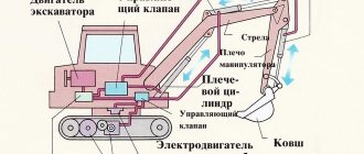
Loader and excavator equipment
MTZ tractors can be equipped with various types of loaders.
There are loaders with hydraulic power from the tractor hydraulic system. They are connected by high-pressure oil lines to the corresponding outlets of the hydraulic distributor through breakaway couplings. Loader versions with their own hydraulic valves are also available. Such models are connected directly to the oil pump, while the hydraulic outputs of the tractor distributor remain free and can be used with other mechanisms.
If it is necessary to equip a tractor with an excavator, the following must be taken into account:
- Most likely, you will have to replace the standard tractor distributor with a more powerful one if the equipment is not equipped with an autonomous hydraulic system. This will protect the hydraulic system from sudden pressure surges and oil overheating.
- If the excavator is equipped with its own hydraulic system, then it is connected directly to the power take-off shaft.
- A special hitch is installed on the tractor, which allows you to shift the center of gravity of the machine towards the boom, which gives greater stability.
- Hydraulic supports are mounted, which also ensure the stability of the tractor during excavation work.
Possible faults
Proper operation of the system is ensured by the use of suitable parts and consumables, as well as timely maintenance. Maintenance comes down to regular oil changes, as well as checking the condition of parts, linings and oil lines.
The oil is changed once a season or after every 2000 operating hours. First start the engine until the oil warms up to 30° C. Then turn off the engine and drain the used oil through the drain hole in the bottom of the crankcase. The hydraulic oil filter is removed and washed in diesel fuel. The washed filter is put back in place and fresh oil is added until about. The recommended brand of hydraulic oil for MTZ 82 is M-8G2K, M-10G2K, M-10G2. At the final stage, start the engine and lower and raise the rear linkage mechanism several times to bleed the hydraulic system.