From the history of the creation of GAZ - 66
The GAZ-66 was launched into mass production in 1964. It was created on the basis of the GAZ-62 and GAZ-63 trucks. The all-wheel drive truck had a payload capacity of 2 tons, a V-shaped eight-cylinder gasoline engine and a 4-speed gearbox. In 1968, a tire pressure regulation system was added to the GAZ-66 design. The model was twice awarded gold medals and received a quality mark. The production of GAZ-66 ceased in 1995, at the moment you can purchase GAZ 66 from military conservation.
Due to what the high cross-country ability of GAZ - 66 was achieved
A number of factors influenced the truck’s high cross-country ability. First of all, this is the use of self-locking differentials in both axles of the car. It is important to shift the center of gravity to the middle of the body, which gives an even distribution of the load on both axles of the car.
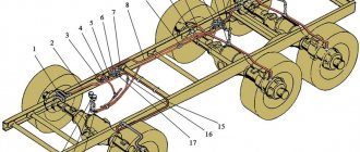
Detailed diagram of the GAZ 66 truck
The high landing of the body allowed the truck to crawl through swampy terrain without touching the bumps and hummocks with its “belly”. Also, due to the short overhangs, the GAZ-66 truck easily overcomes uneven sections of the road. Tires also affected cross-country ability. It’s worth talking about tires in more detail.
Tires used on GAZ - 66
The influence of tires on cross-country ability
The wheels also help the all-terrain vehicle from the Gorky plant to overcome any obstacles with ease. Firstly, the design solution itself - one ramp on the front and rear axles. When passing an obstacle, the front wheels fill a track, and the rear wheels follow them in almost the same tracks, pushing through the same track size (the front wheel track is 1.8 m, the rear wheel track is 1.75 m). Considering the light weight of the GAZ-66 and the fairly large size of the tires, the car does not get bogged down in a swampy environment.
It’s another matter if the rear wheels were gable - then the car would slip on the rear axle.
Secondly, there is a wonderful solution by the designers - to add a compressor for inflating tires to the GAZ-66 truck. The swap really helped. Before the obstacle course, it was first possible to reduce the pressure in all wheels, and after passing a difficult section, pump up the pressure with a compressor.
Inflating also helped in case of tread damage - it made it possible to drive with a punctured tire to a tire shop, constantly maintaining pressure while the car was moving (the compressor is powered by the engine).
But it is worth noting that the standard compressor is quite capricious - it requires constant maintenance. If you just overlook it, it will immediately fail.
Thirdly, this is the use of arched tires on GAZ, lightening the rubber by stripping. Such non-standard solutions increase the ability to overcome difficult sections of the road with greater ease.
Characteristics of standard tires for GAZ - 66
Nowadays, there are still many copies of the “combat” GAZ-66 driving on the roads of Russia (however, not only in Russia).
To begin with, here are the general characteristics of a standard tire that is installed on a car:
- Wheel size – 12.00R18 320x80 R 457;
- Tread pattern – universal;
- The maximum permissible speed is from 80 to 95 km/h;
- Internal pressure with maximum load – 340 kgf;
- Static radius – 505 mm;
- Applicability - on trucks GAZ - 66, ZIL - 157;
- The nominal air pressure in tires is 2.8 kgf/cm2.
Truck tire pressure: table and rules
Long-term safe operation of the vehicle, reduction of fuel consumption, safety of tires and truck suspensions largely depend on the air density inside the wheel tire. You need to look at the recommended truck tire pressure in the table. You should pump air into the tires using a compressor using the data in the table in the manual attached to the vehicle documents.
The Importance of Tracking
Monitoring tire pressure is necessary, since this indicator is strictly linked to many parameters of the efficient and safe operation of a car whose wheels:
- Designed to receive torque from the engine and engage them with the road surface. Weak tires can cause the wheels to spin on the rim, which always has serious consequences.
- Tires are an element of transport, including trucks. They absorb and soften impacts from road unevenness. Lack of air while driving will cause the tires to lose elasticity and, as a result, increase the risk of rapid tread wear.
- They ensure the quality of acceleration and braking of the car; excess and lack of air in the tires has a direct impact on the rate of fuel consumption.
- The stability and smooth movement of transport depends on them.
- The wheels determine the safe steering of the car; the likelihood of the car spontaneously moving to the side increases.
- Low tire pressure can lead to wheel frame failure.
The technical condition of the car ensures safe driving on the highway. Any emergency condition of a car on the road can lead to serious consequences.
To avoid problems while driving on the highway, you need to maintain this criterion at the level recommended by the manufacturer.
The air density parameter in the wheels for each type of vehicle is set individually by the automobile manufacturer.
Watch the video to see how to select the correct tire pressure.
The driver needs to know the current condition of the tires. In cold weather, tire pressure is measured at shorter intervals than in summer.
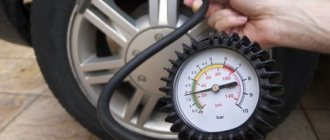
It is recommended to check this indicator once or twice a week, using devices designed for this purpose. A pressure gauge is a basic acceptable and effective design for monitoring pressure.
Basic Techniques
To determine the level of air pressure in truck tires, dial gauges are used, in which the rule of pressure balancing is applied by the force of elastic deformation of a spring made in the form of a hollow twisted tube.
The amount of air pressure in a truck tire is of great importance, as it determines the proportionality of the load on the truck tires. The air density in the wheels of vehicles for transporting goods must be measured at least twice a week. The most reliable device for this procedure is a pressure gauge with two heads with a gradation of at least 8 bar and a scale with an interval of 0.1 bar.
The initial pressure is measured in the wheels of a stationary car when the tires are cold. The air temperature inside the wheels of a car in motion and standing still is significantly different. As you drive, the tire heats up, and the same happens to the air inside. It is capable of expanding and contracting depending on temperature. Pressure as a result of the trip can increase by 25%. To ensure the optimal density in truck wheels, you should rely on the data in the tables, which give the maximum and recommended values.
For a truck, this indicator can have two parameters, which are considered to be basic; they are given in special tables:
- The manufacturer marks the highest value on the side of the tire. This value must not be exceeded for safety reasons.
- Recommended value that must be maintained during axle loading. It is established by calculations and tests carried out by the manufacturer.
The pressure value set by the manufacturer represents the average load on a specific vehicle axle at the highest load on it. This permissible value is indicated in special tables.
Tables of recommended truck tire pressures based on axle load and tire size
Regardless of the time of year, the pressure in truck tires must be the same and have the value recommended by the manufacturer.
When installing winter tires on a truck, it is necessary to take into account the factory recommendations, since tire pressure largely depends not only on the load. Ambient temperature also has a significant impact on this parameter.
In winter, weather conditions are unstable, sudden temperature changes are always possible, so monitoring this indicator should be taken more responsibly:
- When the ambient air temperature increases, due to some softening of the rubber tires, the air inside them will expand, that is, an increase in pressure will be observed.
- When the temperature drops in winter, the rubber becomes hard and cold, which causes compression of the air inside. Then this figure will decrease.
Given these features, this indicator should be monitored and adjusted more often. However, you need to know that this procedure should be performed outside.
By constantly monitoring pressure using the necessary instruments, you will:
- Unforeseen dangerous situations are excluded;
- Braking noise will be reduced;
- Fuel consumption will be reduced;
- The load on the car suspension will be reduced;
- The service life of the wheels will increase.
Experience shows that the pressure in the wheels of trucks significantly affects the cost of its maintenance and the increase in road safety. Therefore, timely and regular monitoring of this indicator is necessary.
carloud.ru
Arched tires - why are they needed?
It seemed that the Shishiga had excellent cross-country ability, what more could you need. But dissatisfied admirers of the 66th want even bigger, fantastic victories over off-road. And in addition to standard tires, they fit everything that rolls onto trucks, trying to find the right size, reducing the pressure in the ramps.
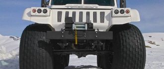
For better cross-country ability, there are arched tires. What can you say about them? The distinctive feature of them is a very wide profile - the width of the arched rubber is two or even three times greater than the usual width of an ordinary tire.
Example of arched gas tires 66
At the same time, the outer size itself remains at a normal level. This design makes it possible to reduce the internal pressure in tires to 0.5-1.4 kgf/cm2, the pressure on the ground is noticeably reduced, distributed over the entire width of the wheel, and due to this, the maneuverability of the equipment is significantly increased.
GAZ-66-11. Tire pressure control system (device)
The tire pressure regulation system provides change and control of tire pressure from the driver's seat both when parked and while driving, depending on the nature of the road surface and the speed of the vehicle. Reducing the air pressure in the tires when driving on soft ground reduces the specific ground pressure and increases the vehicle's maneuverability. In case of minor damage to the inner tube, the tire pressure regulation system allows the vehicle to continue driving without having to immediately change the wheel, since the compressor replenishes the air leakage from the inner tube. The tire pressure regulation system (Fig. 180)) consists of a compressor 1, an air cylinder 4, a control valve 10, a pressure regulator 3, a safety valve 5, a single safety valve 8, wheel air shut-off valves, seal blocks installed in the axle axles , pressure gauge 9, pipelines and hoses.
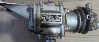
Compressor
(Fig. 181) piston type, single-cylinder, air-cooled, driven through pulley 7 together with the power steering pump by two belts from the engine crankshaft pulley. Air from the engine air filter enters the compressor cylinder through the reed inlet valve. Compressed air is forced into the pneumatic system through a plate discharge valve. Lubricant is supplied to the compressor from the engine lubrication system. The compressor has a device to maintain the required air pressure in the system. It consists of a 6 unloading cylinder mounted on the compressor head and a pressure regulator.
When the air pressure in the system reaches 7...7.35 kgf/cm2, the pressure regulator connects the unloading cylinder 6 with the air cylinder, as a result of which air under pressure enters the unloading cylinder and moves the piston of the unloading cylinder down. The piston rod of the unloading cylinder, moving downwards, opens the valve and thus connects the cavity of the compressor cylinder with the engine air filter, as a result of which when the compressor piston moves upward (compression stroke), air is forced back into the air filter, and not into the system, i.e. the compressor works without load. When the air pressure in the system decreases to 5.65...6 kgf/cm2, the pressure regulator connects the unloading cylinder to the atmosphere. The piston of the unloading cylinder with the rod rises upward under the action of the spring, the inlet valve is released, and the compressor again begins to pump air into the system.
Rice. 180. Diagram of the tire pressure regulation system: 1—compressor; 2—unloading cylinder; 3—pressure regulator; 4—air cylinder; 5—safety valve; 6—air bleed valve; 7—condensate drain valve; 8—protective single valve; 9—pressure gauge; 10—control valve; 11—control valve handle
Rice. 181. Compressor
Rice. 182. Pressure regulator:
Rice. 183. Control valve
Rice. 184. Air valve
The pressure regulator (Fig. 182), together with the unloading cylinder, automatically maintains the pressure in the system within the range of 5.65...7.35 kgf/cm2 by admitting and releasing air from the unloading cylinder. When the pressure in the system increases to 7...7.35 kgf/cm2, valve 9, under the influence of this pressure, overcoming the force of the spring, rises until valve 13 is pressed against seat 6. In this case, compressed air from the system through filter 12 will flow into the unloading cylinder, as a result of which air injection into the system will stop. When the pressure in the system drops to 5.65...6 kgf/cm2, the regulator spring overcomes the force of compressed air pressure and lowers the balls down, as a result of which the unloading cylinder is disconnected from the system and connected through the outlet channels to the atmosphere. The compressor inlet valve is released and the compressor begins to force air into the system.
The air cylinder is designed to settle the condensate of water vapor and oil entering the system from the compressor along with compressed air. The cylinder has a safety valve, a tap for draining the condenser and an air bleed tap. The safety valve serves to protect the system from excessive pressure increases in the event of damage to the automatic pressure regulator and is adjusted so that it opens when the air pressure in the system reaches 10... 10.5 kgf/cm2. A spool-type control valve (Fig. 183) allows you to connect the wheel chambers with the compressor (when inflating the tires with air), the atmosphere (when reducing the air pressure in the tires) or locking them (if you need to maintain the existing air pressure in the tires). Moving relative to body 1 in one direction or another from the middle position, spool 8 can connect the cavity communicating with the wheel chambers with cavities communicating with the compressor or atmosphere. The control valve spool has three positions. The left one corresponds to tire inflation, the right one corresponds to deflation of air from the tires, and the middle one corresponds to neutral. The neutral position of the control valve is fixed by a handle in the bracket, and the “Increase pressure” and “Decrease pressure” positions are fixed by the locking ring 6, respectively, focusing on the support washer 5 and the nut 7.
The spool of the traction control valve is connected to the handle of the valve, mounted in front on the middle part of the removable cabin floor. There is a sign on the instrument panel indicating the position of the control valve handle. To switch, the tap handle is lifted up and rotated to the desired position.
The air valve (Fig. 184) serves to supply air to the wheel chambers. It consists of a body 2, seals 4, a stopper plug 6, union nuts 1 and 5 and washers 3.
The air supply to the front wheel is shown in Fig. 185 and to the rear wheel in Fig. 186. The main part of the sealing device in the trunnion is rubber cuffs, which are collected in a package.
Rice. 185. Air supply to the front wheel: P - cavity; 1 air supply hose; 2—channel for air supply; 3—air supply tube; 4—air valve
Rice. 186. Rear hub and wheel. P—cavity; 1—trunnion; 2—bolt puller; 3—flange cover; 4, 6—bearing nuts; 5— lock washer; 7—hub; 8—air supply tube; 9—wheel; 10—brake; 11—bypass valve; 12, 15—oil seal; 13—bridge beam; 14—axle shaft
content .. 81 82 ..
Low pressure tires and tire stripping
A good solution for overcoming difficult sections of the road is to use low-pressure tires. Such a tire does not put pressure on the ground, it sort of adapts to the obstacle, taking its shape, the area of contact with the ground increases due to the softness of the tire. The disadvantage of such tires is that they are not for high-speed driving and wear out quickly on hard surfaces.
And here’s the problem - the cost of a set of such tires is sometimes almost equal to the cost of the car itself. And owners of GAZ-66 and similar all-terrain vehicles go to great lengths just to get the effect of low-pressure tires.
gas 66 with low pressure tires
What is tire stripping and what does it give?
Tire stripping is the removal of a portion of the cord from the outside of the tire. At the same time, the tire becomes lighter and much softer, and acquires the properties of a low-pressure tire. Stripping a tire is a very tedious and painstaking task.
Due to inexperience, a tire can be damaged, so it is better to practice first on a tire that you won’t mind throwing away. On GAZ-66 it is often practiced to rip off Kirov K-70 tires. It is unknown whether such tires will last long, and after such a procedure you should not drive on asphalt roads on these tires.
the process of stripping a tire for gas 66
Of course, wheels play a big role in the cross-country ability of the GAZ-66, but is it worth it to strain so hard in pursuit of incredible results? Isn’t it easier to leave the standard wheels as is, after all, the manufacturer carried out the tests for a reason and has already invented the bicycle before us.
GAZ-66 Shishiga › Logbook › Restoring automatic wheel inflation (part 1)
It happened, as always, unexpectedly - one fine day I decided to try to restore the tire inflation on Gazik.
A quick inspection showed that half of the parts were present. Namely: — compressor (of course); — air tank (receiver); — pressure regulator; — tubes (except for those that go to the pressure control valve. There is no valve itself either).
I decided to start my search with the pressure control valve, as a key element).
On the first day at the car market, they slipped me a part that turned out to be a pressure regulator from another car, but I realized this already at home. The next day I had to return her and continue the search. I spent two hours at the market, hoping to find at least some elements from the system, such as fittings and three-pieces. As usual, luck smiled when I was about to go home. In one place there was a lot of everything on the 66th.
Since I was limited by finances and did not fully understand the whole scheme, I limited myself only to: Pressure control valve (6,000 tenge), corner fittings (2x500 tenge), connection for the 12th tube (500 tenge), clamps (100 tenge) and high pressure hose (6x200tg).
The first step was to assemble a minimal system (compressor+pressure regulator+receiver+monometer) and test it for leaks.
I started the car - the pressure gauge needle joyfully crawled up, accompanied by a growing whistle from under the floor of the cabin. Looking down, I found a place where air was escaping from the system without a care in the world. Tightened it and started it again. The operation had to be repeated 6 times. After which, there was only one place left that did not want to be sealed. It was a pressure regulator.
I remove, disassemble, soak in acetone and wash small parts with WD-40. Inside was a battered copper porous insert, the size of a small coin. There is still nothing to replace it with - I had to put it back. If previously the air came out in three places only on the regulator, now there is only one left - at the top. Which in theory should operate at maximum pressure. But I still don’t understand how this thing works.
Judging by the soap foam, this was the last place where the air was leaking from and I decided to move on to the next stage - connecting the pressure control valve. I put it in place, screwed on the corner fittings (I had to wind the thread onto the threads so that they would fit in the desired position). And he moved on to the stage of searching for supply pipes into the general system. I'm thinking of starting with ready-made high-pressure tubes. Because making original copper ones is more problematic.
As testing progressed, I realized that the pressure gauge was a little out of order - the bent arrow limits it to 4 atmospheres, and after that it is necessary to knock on it so that the arrow begins to move further. And his movements are very sharp and not always predictable.
You will have to disassemble the pressure gauge, as well as look for the missing elements of the system.
This completes the first stage, to be continued)
PS: the diagram was found on the website gaz66.ru, many thanks to its author.
Source: www.drive2.ru