Dimensional parameters of excavators with rigid equipment suspension
When working with a straight shovel
Table 21
| Index | EO-4121A | EO-4123 | EO-4321 | EO-5122 | EO-6121 |
| Digging depth below parking level, m | 3,6 | 3,34 | 3,04 | 4,13 | 4,85 |
| Minimum digging radius, m | 4,12 | 4 | 4 | 4,7 | 5,3 |
| Maximum digging radius, m | 7,25 | 7,45 | 7,45 | 8,93 | 10,15 |
| Maximum lifting height of the bucket, m | 7,5 | 7,4 | 7,7 | 9,65 | 10,3 |
| Maximum unloading height, m | 5,03 | 6,1 | 6,4 | 5,1 | 4,95 |
| Unloading radius at the highest unloading height, m | 5 | 6 | 6 | 4,62 | 6,7 |
When working with a backhoe
Table 22
| Index | EO-3121B | EO-3322A | EO-4121A | EO-4123 | EO-4121 | EO-5122 |
| Handle length, m | 2,8 | 2,58 | 2,99 | 2,93 | 2,93 | 2,97 |
| Maximum digging depth, m: | 4,5 | 4,2 | 5,8 | 5,6 | 5,5 | 6 |
| Maximum digging radius, m | 7 | 7,6 | 9,2 | 8,95 | 10,16 | 9,6 |
| Maximum unloading height, m | 5,5 | 4,7 | 6 | 5,88 | 6,18 | 5 |
Machines and devices for auxiliary work
Table 23
| Index | DP-8A | DP-3 | DP-2 | D-695A | DP-25 |
| Basic tractor | Crawler DT-75B-S2 | Crawler T-100MZGP | Crawler T-100MZ | Tracked T-100MZGBP | Tracked T-130.1G-1 |
| Engine power, kW | 55,1 | 79,4 | 79,4 | 79,4 | 117,6 |
| Blade width, m | 2,13 | 1,5 | 1,54 | 3,53 | 1,38 |
| Overall dimensions, m: | |||||
| length | 5,05 | 5,61 | 5,55 | 6,36 | 5,83 |
| width | 2,68 | 3,3 | 3 | 3,87 | 3,25 |
| height | 2,3 | 3,05 | 3,05 | 2,75 | 3,05 |
| Working width, m: | |||||
| uprooter | 0,72 | 1,38 | 1,38 | 2,09 | 1,38 |
| uprooter-gatherer | 2,18 | 1,38 | 1,38 | 3,53 | 1,38 |
| Largest diameter of uprooted stumps, m | 0,5 | 0,45 | 0,45 | 0,5 | 0,45 |
| Produce activity: | |||||
| When uprooting stumps, pcs/h | 45 | 40 | 40 | 59 | 40 |
| When uprooting bushes and collecting stumps, ha/shift | 1,6 | 3,5 | 3-5 | 2,4 | 3 |
Drilling machines
Table 24
| Index | BM-204 | BM-205 | BM-202 | BM-302 | BM-802S | BM-303 | BM-251 |
| Basic car | Wheel tractor | Automobile GAZ-66-02 | Automo bill | Crawler | |||
| MTZ-52L | MTZ-82L | KrAZ-257 | T-74-S2 | DT-75-S2 | |||
| Drilling depth, m | 2,1 | 2 | 2 | 3 | 8 | 3 | 2,5 |
| Well diameter, m | 0,35; 0,5; 0,8 | 0,35; 0,5; 0,8 | 0,35; 0,5; | 0,8 | 0,3; 0,4; 0,65 | 0,35; 0,5; 0,8 | 0,6; 0,8; 1 |
| Bulldozer blade: | |||||||
| length, m | 2 | 2,1 | — | — | — | — | — |
| height, m | 0,65 | 0,64 | — | — | — | — | — |
| Overall dimensions in transport position: | |||||||
| length | 6,3 | 6,1 | 6,55 | 6,55 | 12,41 | 5,67 | 4,88 |
| width | 2 | 2,25 | 2,34 | 2,34 | 2,78 | 2,15 | 1,75 |
| height | 3,96 | 3,72 | 3,05 | 3,37 | 3,93 | 3,74 | 3,16 |
| Overall dimensions in working condition position: | |||||||
| length | 6,2 | 6,1 | 6,55 | 6,55 | 12,41 | 4,8 | 4,7 |
| width | 2 | 2,25 | 2,34 | 2,34 | 2,78 | 2,15 | 1,75- 2,27 |
| height | 5,16 | 4,8 | 3,65 | 4,2 | 3,93 | 8,85 | 3,96 |
studfiles.net
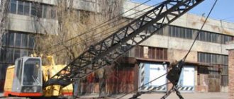
Excavator EO-4111B (technical characteristics)
| The EO-4111B excavator with a 0.65 m3 bucket on a crawler track has replaceable working equipment: forward and reverse shovels, a dragline, a crane and a grab. This is how the E-652B excavator from the Kovrov plant began to be labeled after the introduction of a new indexing system for machines for excavation work. The E-652BS excavator, designed for work in low temperature conditions, began to be labeled as EO-4111BS. Excavator EO-4111B The rotating platform of the excavator contains: a power unit, reverse mechanisms, main and boom winches, mechanical transmissions, a turning mechanism, a cabin with a control panel and a rack for hanging the boom. The drums of the main and boom winches are equipped with friction clutches and band-type brakes. The couplings of the turning mechanism and the boom-lifting winch are conical. The rotating platform is connected to the chassis by a roller slewing bearing. Each track has a locking device. The excavator control is pneumatic. Technical characteristics of EO-4111B
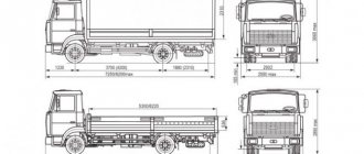
Overall dimensions of EO-4111B Dimensional parameters when working with a straight shovel
Dimensional parameters when working with a backhoe
Dimensional parameters when working with a dragline
Dimensional parameters when working with a side dragline
Dimensional parameters when working with a grab
zinref.ru | |||||||||||||||||||||||||||||||||||||||||||||||||||||||||||||||||||||||||||||||||||||||||||||||||||||||||||||||||||||||||||||||||||||||||
9.1.7. Tracked bogies. E 652b
The E-652B excavator with a 0.65 m3 bucket is an improved model of the E-652A excavator from the Kovrov plant. The E-652BS excavator is a special machine designed to work in the Far North. Excavator E-652BTechnical characteristics of excavators E-652B and E-652BS
| Replaceable work equipment | straight and reverse shovel, dragline, grab, crane, pile driver |
| Brand | diesel D-108 |
| Engine power, hp | 75 — 82 |
| Control | pneumatic |
| Travel speed, km/h: | |
| ..first | 1,7 |
| ..second | 3,01 |
| Minimum working cycle time for a straight shovel, sec | 15 |
| Design capacity for straight shovel, m3/h | 156 / 192 |
| Total weight of the excavator, t | 21,25 |
| Specific ground pressure, kg/cm2 | 0,65 |
| Crane boom length, m | 10 / 18 / 18 with single file |
| Maximum load capacity, t | 10 / 7,5 / 2,5 |
Since the diesel power in the D-108, installed on the E-652B excavators, is excessive, it is limited to 75 - 82 hp. by regulating fuel equipment and reducing engine speed. When installing forward and reverse shovels, the excavator is equipped with buckets with a capacity of 0.65 m3 with a rectangular cutting edge and teeth. The machine can also use a straight shovel bucket with a capacity of 0.8 m3 with a semicircular cutting edge; the dragline was produced only with a bucket with a capacity of 0.8 m3 with a semicircular cutting edge.
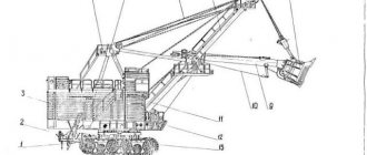
The power unit 1 is located in the rear part of the turntable 27. A radiator is installed on the right side of the diesel engine, and the main coupling 18 is installed on the left side. A chain reducer, covered by a casing 19, connects the diesel shaft to the shaft 15 of the reverse mechanism. The cylindrical gears connecting the horizontal shafts 15, 13 and 12 of the mechanisms on the platform are covered with a casing 21. Double-cone clutches 36 of the reverse mechanism are visible from the outside, and the bevel gears of this mechanism are inside the box 37. For safety, the reverse mechanism is covered from above with a shield 3. Double-cone clutch 20 of the reverse the main winch is located on the left console part of the shaft 13, and the boom lift winch drum 34 is located on the right side. Using a double-sided cam clutch 35, either a drum 34 or a sprocket of the main winch reverse chain drive 33 is connected to the shaft 13. The mechanism for limiting the speed of lowering the boom is covered by a casing 14. The bucket lifting drum 30 and chain sprockets 24 of the pressure mechanism are located on the shaft 12 of the main winch. The mechanisms for lifting the bucket and the pressure of the handle are stopped by brakes 23 and 31, controlled by pedals. The rotating platform 27 is a complex welded structure consisting of longitudinal and transverse beams and two posts. In the middle part of the platform there is a box in which the vertical shafts of the reverse, rotation and travel mechanisms are located. Horizontal shafts 12, 13 and 15 of the reverse mechanisms, boom and main winches, as well as a two-legged stand 4 for attaching the boom lifting tackle are mounted on the racks. A compressor 16 is installed on the platform under the diesel radiator. In the front part there is a control panel 28 with a driver's seat 8. In the eyes 26 of the transverse beam of the platform, the booms of the working equipment, an additional stand of the backhoe and the drum of the pressure mechanism are secured. The rear box 17 of the platform, connecting both longitudinal beams, contains a fuel tank. The entire platform with the mechanisms located on it is covered by a cabin. Spotlights 5 and sound signals 6 are placed on top of the cabin.
| Main clutch of excavator E-652B |
The E-652B excavator uses an open-type single-disc friction clutch, designed for smooth connection and quick disconnection of the engine shaft with the main transmission of the excavator. The main clutch is controlled from the driver's seat.
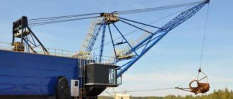
| Main winch of the E-652B excavator (the bottom picture is more visual) |
The reverse mechanism is designed to change the direction of rotation of the driven shaft while maintaining the same direction of rotation of the drive shaft. The E-652B excavator uses a reverse mechanism design with bevel gears and double-cone clutches. The clutches are activated by pneumatic cylinders mounted on threads at the ends of the shaft and rotating with it. When air enters under pressure into the cylinder cavity, the piston transmits force to the rod 9, which passes through the axial drilling of the shaft 6. At the end of the rod there is a fork, with which it rests against a pin (thrust bar) located in the slots of the shaft 6. 3. The ends of the pin protrude beyond the shaft press on the ends of the hub of pulley 2 (or pulley and move it, compressing the return spring 5 and pressing the pulley against the friction pads 4. This sets in motion one or the other bevel gear 7, which is in constant mesh with gear 10, mounted on the splines of the vertical shaft 14. From shaft 14, the movement is transmitted to the rotary and running mechanisms of the excavator through the double gear 15 and gears 12 or 13, mounted on the splines of the vertical intermediate shaft 11. Using the roller 17 and fork 16, gear 15 can be engaged with gear 13 or gear 12 Gear 13 is in constant mesh with a gear (not shown in the figure) located on the shaft of the rotary mechanism.
| Reverse mechanism with bevel gears of the E-652B excavator |
| Pressure drum of the E-652B excavator |
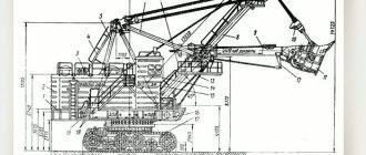
Kinematic diagram of the E-652B excavator. The features of the kinematic diagram of the E-652B excavator include: 1) on the turntable, three main horizontal shafts are located in the same plane - shaft 8 of the main winch, intermediate shaft 7 and shaft 27 of the reversing mechanism; 2) the boom-lifting mechanism can work simultaneously with the platform rotation mechanism and independently of it; the movement of the boom-lifting mechanism is transmitted by gears; 3) the reverse of the platform rotation mechanism and the excavator running gear is carried out by bevel gears and double-cone clutches, and there are two rotation and movement speeds; 4) the working equipment of the straight shovel has a rope pressure mechanism.
| Kinematic diagram of the E-652B excavator and a visual arrangement of gears (the designations are the same) |
Initially, the design of the chassis provided for a two-support scheme for transmitting motion to the drive sprocket of the excavator, as a result of which the bearing located between the drive wheel and the sprocket carried a large load and wore out relatively quickly. Therefore, they began to use a three-legged structure (see diagram). The third support bearing is located at the end of a special adjustable support rod, the second end of which can rest on the lower part of the running frame or on the track frame bracket.
| Crawler trolley of the E-652B excavator |
Excavator pneumatic control. From the atmosphere, air enters the first stage of the compressor 17, driven by a diesel engine by a V-belt drive, first into the oil and moisture separator 1, then into the second stage of the compressor, and from it, under pressure up to 7 kgf/cm2, it is pumped into the sectional cooler 13 and the pneumatic distributor 11. When turned on adjustable pneumatic devices 8 and pneumatic valves 4, compressed air enters the pneumatic chambers 5 or pneumatic cylinders 7 and performs the necessary work to turn on the machine mechanisms. When the adjustable pneumatic device 8 or the pneumatic valve 4 is turned off, the air from the chamber (cylinder) is released into the atmosphere through the pneumatic device 8 and the quick release pneumatic valve 6. From pneumatic distributor 11, air also flows to signal 3, windshield wiper, pressure gauge 10 and load moment limiter (with crane equipment).
| Pneumatic control diagram for excavator E-652B |
The electrical equipment of the excavator consists of engine starting, lighting, heating, ventilation and alarm systems. In this case, a single-wire electrical system is used. The sources of electrical energy on the E-652B excavator are a diesel-powered generator 1 AC GT-1A with a rated voltage of 12 V and a power of 300 W and a battery 16. Inside the excavator is illuminated by three lamps 31, 32, 33, switched on by switch 34. Work site in front of the excavator is illuminated by three headlights 35, 36, 37, switched on by switch 38. The instrument panel is illuminated by a control lamp 6, switched on by a rotary switch located on the lamp socket. To illuminate the excavator's mechanisms during maintenance, a portable lamp is used, which is plugged into plug socket 7. Electric motor 4 of the DC fan installed in the driver's cabin to ventilate the cabin in the hot season is powered from generator 1 through rectifier 3 and turned on by switch 5. On the starting motor diesel engine, an electric starter 17 is installed. When starting with a starter, you must turn on the switch 15 of the battery 16, then turn on the starter 17 by pressing the lever of the starter button 18 (short-term activation) until the engine starts. During operation of the D-108 diesel engine, battery 16 is recharged from generator 1 through rectifier 3. The degree of charging and discharging of the battery is controlled by ammeter 19. Deviation of the ammeter needle to minus corresponds to battery discharge, and deviation to the right indicates charging. Fuse block 2 protects the generator from short circuits and overloads. Switches for headlights, lamps, fan, power socket, ammeter and control lamp are located on the instrument panel, which is located on the cab wall to the left of the driver. On the same panel there are monitoring devices (pressure gauges and thermometers) for the operation of the engine and compressor.
| Electrical diagram of the E-652B excavator |
All main operations in the working cycle are performed using levers 1 and 2, each of which has four working positions and one neutral.
| Control levers and pedals for the E-652B excavator |
Schemes for reeving ropes when working with various equipment
The working equipment of the E-652B excavator can be found in the section “Working equipment of mechanical excavators”
Technical characteristics of single-bucket excavators
Technical characteristics of single-bucket excavators
| Brand | Bucket capacity, m3 | diggingRadius, m | Digging depth, m | unloadingHeight, m | power, kWt | Weight, t | Productivity, m 3/h | Estimated operating price of the machine, h, r. |
| Backhoe excavators | ||||||||
| EO-2621V-3 | 0,25 | 5,3 | 4,15 | 3,2 | 44 | 6,1 | 18 | 10,2 |
| EO-3323A | 0,63 | 7,9 | 4,8 | 6,05 | 55 … 73 | 13,8 | 40 | 14,4 |
| EO-3122A | 0,63 | 8,1 | 5,2 | 5,7 | 55 … 73 | 14,3 | 40 | 13,3 |
| EO-4121 | 0,65; 1 | 9 | 5,8 | 5 | 95 | 19,2 | 40 | 12,4 |
| EO-4321 | 0,65; 1 | 9 | 5,5 | 5,6 | 59 | 19,2 | 40 | 13,5 |
| EO-4124B | 1 | 9,4 | 6 | 5 | 95,6 | 25 | 50 | 18,5 |
| EO-5122 | 1,25; 1,6 | 9,4 | 6 | 5 | 125 | 35,8 | 60 | 25,3 |
| Poklen75RV | 0,77 (0,28 | 7,9 | 4,6 | 6,2 | 79,5 | 14,4 | 50 | 16,5 |
| (France) | … 1) | |||||||
| Poklen75SK | 0,77 (0,22 | 7,9 | 4,85 | 5,95 | 58,1 | 15,4 | 50 | 16,5 |
| (France) | … 1) | |||||||
| Liebherr R- | 0,6 | 8,8 | 6,2 | 5,5 | 50 | 15,9 | 40 | 26,8 |
| 900 (Germany) | (0,18…0,6) | |||||||
| Liebherr A- | 1 (0,24… | 9 | 5,83 | 6 | 100 | 20,9 | 50 | 24,1 |
| 922 (Germany) | 1,3) | |||||||
| Poquelin 90R | 1,15 | 9,2 | 5,65 | 6,75 | 77,3 | 19 | 60 | 23,4 |
| (France) | (0,23…1,15) | |||||||
| Hitachi IN- | 1 (0,9… 1,4) | 10,52 | 7,2 | 7,02 | 121 | 26 | 60 | 24,3 |
| 123 (Japan) | ||||||||
| Front shovel excavators | ||||||||
| EO-2621V-3 | 0,25 | 5 | 2,85 | 2,5 | 44 | 5,45 | 20 | 10,2 |
| EO-3323A | 0,63 | 6,8 | 7,66 | 4,2 | 59 | 14,5 | 40 | 14,4 |
| EO-3122 | 0,63 | 6,8 | 7,3 | 4,1 | 55…73 | 14,3 | 40 | 13,3 |
| EO-4321 | 0,8 | 7,4 | 7,9 | 5,7 | 59 | 19,2 | 50 | 13,5 |
| EO-4123 | 0,8 | 7,4 | 7,6 | 4,4 | 95 | 18 | 60 | 16,3 |
| Dragline excavators | ||||||||
| EO-3211E-1 | 0,45;0,5 | 11,1 | 5,3 | 3,83 | 37 | 12,9 | 30 | 11 |
| EO-4112A | 0,65;1 | 14,3 | 6,6 | 5,3 | 66 | 24,5 | 40 | 13,6 |
| EO-5ShB | 1 | 16 | 7,8 | 5,3 | 103 | 32 | 65 | 15,4 |
studfiles.net
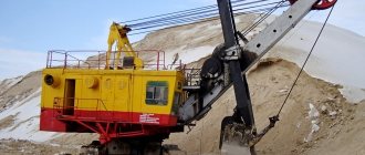
Technical characteristics, photos and videos of the EO 5126 crawler excavator
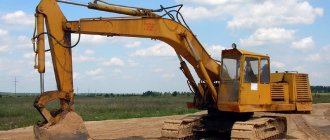
The EO-5126 excavator belongs to the class of heavy earth-moving equipment of the 5th size group. It is used in quarries, when digging pits, trenches, laying canals, demolishing structures, and in many other jobs that require high power and efficiency of the equipment used.
Features and advantages of the EO-5126 excavator
A single-bucket universal hydraulic excavator built on a tracked chassis, model EO-5126, is produced by Uralvagonzavod OJSC. It is designed to work with soils up to category 4 inclusive, as well as with frozen or rocky rocks, subject to their preliminary loosening.
For the convenience of the operator, the installed cabin is protected from vibrations and the penetration of extraneous noise. The large windshield is equipped with two windshield wipers. For comfortable work at low temperatures, the cabin is equipped with a heater.
Photo of excavator EO-5126
The condition of components and assemblies is monitored by an automatic system, displaying a fault message on a light display. Ease of operation does not require extensive training of personnel to operate this model.
The EO-5126 crawler excavator combines simplicity of design, ease of access for inspection to all components and assemblies, ease of maintenance and repair, up to field conditions.
"Standard"
The “standard” version of the EO-5126 excavator is designed to work in the widest temperature ranges, in northern conditions with frosts down to -40?C, and in regions with heat up to +40?C. For such conditions, all-season oil can be used.
"Tropical"
For work in climatic conditions with high temperatures, up to +55? C, the “tropical” version of the excavator is designed.
Working equipment
In most cases, a backhoe bucket is used for excavation work in quarries, when laying trenches, on construction sites, and during road construction. In addition to the installed standard attachments, the excavator can use interchangeable working tools.
Standard
The main working tool is a backhoe bucket with a capacity of 1.25 m3. To open the road surface and loosen rocky, heavy or frozen soils, a loosening tooth weighing 221 kg and with a force on the working cutting edge of up to 280 kN is designed.
Standard equipment includes: monoblock boom with handle, hydraulic cylinders, pipelines.
The Kovrov railway workshops began to function for their intended purpose in August 1864. Since 1866, the Kovrov railway workshops were engaged not only in repairs, but also in the construction of railway cars of their own design.
During the years of Soviet power, the Kovrov workshops were reorganized into a repair plant. In 1930, an order was received there to repair a batch of imported excavators. This circumstance determined the future fate of the enterprise. When the question arose about the possibility of producing domestic earth-moving machines, it was decided to establish an excavator plant in Kovrov on the basis of the previous workshops. The first Soviet excavator "Kovrovets" - a railway-powered steam engine with a bucket with a capacity of 2.5 m3, was built at the plant in April 1931. A total of 177 machines of this brand came out of the factory workshops. Since 1934, the Kovrov Excavator Plant (KEZ) switched to the production of steam full-rotary crawler excavators PPG-1.5 with a bucket capacity of 1.5 m3, and since 1936 it began developing a diesel earthmoving machine on LK-0.5 tracks. In the 1930s, the plant also produced cranes. Kovrov excavators were used at all the largest construction projects in the country, including the construction of the White Sea-Baltic Canal and the Moscow-Volga Canal.
Long before the end of the war, in 1944, the plant began designing a new single-bucket excavator. At the end of 1945, for the first time in the USSR and in world practice, factory engineers and technologists designed and put into industrial production a universal full-rotary mechanical excavator E-505 with hydraulic control and a bucket with a capacity of 0.5 m3. For the creation of this machine, a group of factory designers was awarded the Stalin Prize. In the 50s, the plant produced diesel excavator-cranes E-656 on pneumatic wheels with a bucket with a capacity of 0.5 m3 and a lifting capacity of 10 tons, as well as drilling and crane machines BKGM-AN-63, designed for drilling depressions with a diameter of up to 0.5 m and a depth of up to 1.7 m and installation of poles up to 9 m long and weighing up to 600 kg.
Since 1956, the production of mechanical full-rotary excavators E-651 with hydraulic control and bucket capacity increased to 0.65 m3 began. In the 1960s, the aging model underwent several major upgrades: first, the E-652A modification with pneumatic control appeared, and in 1968, the E-652B modification went into production, which turned out to be so successful that it was produced without significant changes for about 20 years. The E-652BS excavator is a special modification designed for work in the Far North. In April-May 1970, production of the E-652B was also launched at the Donetsk Excavator Plant in the city of Donetsk, Rostov region. According to the indexing system existing in 1960, the name E-652B stood for “excavator with a bucket with a capacity of 0.65 m³, second model, second modification.” In January 1969, the E-652B excavator was awarded the State Quality Mark. This was the first product of the enterprises of the Vladimir region - the first excavator in the country to receive such a high rating, and absolutely deservedly so: a simple and reliable design allowed the machines to work for a very long time in a wide variety of operating conditions, and they are sometimes found in working condition in our time.
In the early 1970s, a course was set for the widespread use of hydraulic drives for excavators. The ministry's plans provided for a complete transfer of the main excavator factories (Kalinin, Leningrad, Kovrov and Voronezh) to the production of machines with hydraulic drive. But there are works or regions of use where the use of hydraulic technology is impossible or irrational - this is in reclamation work and in industrial quarries, when constructing pile foundations, as well as under extreme temperature conditions, where hydraulic technology is weak and powerless. Therefore, the Donetsk and Kostroma excavator plants retained the production of traditional cable (rope) excavators.
In 1985, the index of the manufactured E-652B machine was brought into compliance with the new industry standard for the naming of special equipment - the excavator began to be called EO-4111B, the E-652BS excavator, designed for work in low temperature conditions, began to be labeled as EO-4111BS. In 1986, modification “B” appeared, and in 1988, “G” with a completely changed appearance. The decoding of the index, according to the standard, is as follows: “EO” - single-bucket excavator, “4” - operating weight from 19 to 30 tons (our excavator had a mass of 21.2 tons), “1” in the second position - crawler, “1” in the third position - cable working equipment, "1" in the fourth position - model serial number, "Letter" - modification.
Excavators E-652B with a bucket capacity of 0.65 m3 are designed for excavation work in soils of categories I - IV and V - VI finely crushed (the size of the pieces is no more than 300 - 400 mm), as well as as a crane for loading and unloading operations. The E-652B was equipped with a D-108 diesel engine with a power of 108 hp. Since the power of the D-108 diesel engine installed on E-652B excavators is excessive, it is limited to 75 - 82 hp. by regulating fuel equipment and reducing engine speed. Performing a variety of types of work is ensured by the presence of replaceable working equipment: forward and reverse shovels, with a grab bucket, as well as a dragline, crane and pile driver. When installing forward and reverse shovels, the excavator is equipped with buckets with a capacity of 0.65 m3 with a rectangular cutting edge and teeth. The machine can also use a straight shovel bucket with a capacity of 0.8 m3 with a semicircular cutting edge; the dragline was produced only with a bucket with a capacity of 0.8 m3 with a semicircular cutting edge.
With all the modernizations and improvements of excavators, their fundamental design and kinematic diagram have remained unchanged.
Rotary platform of welded box structure. Its cavities are used as baths to lubricate the gears and bearings of the transmission located inside the platform. The winch frames and excavator transmission supports form an integral part of the turntable and are welded to it in one block. The platform contains an engine, a chain drive, a reversing mechanism, a reverse mechanism for the main winch, a main winch, a rotary and upper running gear, hydraulic control mechanisms and a two-legged stand for hanging working equipment from it.
The rotating platform rests on the undercarriage through a multi-roller support circle mounted on the end surface of the rotating mechanism ring gear. Return rollers are attached to the bottom of the turntable, relieving the central shaft from horizontal forces.
The running equipment of excavators is a multi-support tracked cart. The running frame of the trolley is made of cast steel with a cast slewing ring welded to it with internal gearing. Two cast track frames are welded to the sides of the running frame, which are supported by six road wheels each. At the ends of the frames there are drive and guide wheels, which are encircled by a closed caterpillar chain (tape) of 29 links. To support the upper branch of the track chain, two support rollers are installed on each track frame.
Working equipment. The excavator can be equipped with a front or backhoe, dragline, grab, crane, pile driver, diesel hammer with wedges, etc. In order to increase the productivity of the excavator in light soils, it is possible to use buckets with an increased capacity of 0.75 and 1 m3. When equipped with a straight shovel, the pressure mechanism for the E-652 excavator is independent or combined. To loosen frozen soils when excavating pits in winter, special replaceable working equipment is used.
The control of the E-652 excavator is pneumatic. Positive qualities of pneumatic control: ease and smooth engagement of clutches, reduction of dynamic loads in structural elements, elimination of oiling of friction pads, no need for oils and ensuring cleanliness on the machine. Air is pumped under a pressure of 6 - 7 atm using an O-38 compressor