Air Dryer
9.1. Air Dryer.
Purpose.
An air dryer, shown in Figures 211 and 212, is installed in air brake systems to dry and clean the air coming from the air compressor and to regulate the operating pressure in the brake system.
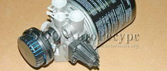
Figure 211. External view and internal structure of the air dryer. Designations: 1 - Inlet; 2 - Control piston;3 - Outlet;4 - Channel;5 - Channel; 6 — Muffler;
7 — Exhaust; 8 — Exhaust valve; 9 — Moisture separation chamber; 10 — Check valve; 11 - Jet; 12 - Ring filter; 13 - Drying agent; 14 - Air regeneration receiver; 15 — Adjusting screw. Inlets: 1 - Supply inlet; 21 - Outlet (to the four-circuit safety valve); 22 — Branch (to the regeneration air receiver); 3 - Atmospheric output
The use of an air dryer eliminates the need to use moisture removal equipment based on additional cooling and automatic condensate drain valves, as well as additional antifreeze (alcohol) injection equipment.
The advantages of a dehumidifier over traditional air conditioning are as follows.
-There is no corrosion of brake system elements caused by condensation.
-The number of failures in the operation of components and assemblies of the brake system is reduced due to the absence of condensate and oil film.
- Low maintenance costs.
-Pressure regulation occurs in a zone of purified air, as a result of which the likelihood of malfunctions in the operation of the pressure regulator is reduced.
Air dehumidification occurs due to the adsorption of moisture at the molecular level by a drying agent (13). Compressed air is forced through the granular, highly porous powder. During this process, any water vapor in the air is deposited on the granules. To regenerate the powder, part of the dried air is discharged into the atmosphere, passing through the powder in the opposite direction. As a result of the decrease in pressure, the partial pressure of water vapor in the regenerating air (i.e., the dryest possible air) also decreases, which allows this air to absorb moisture deposited on the granules.
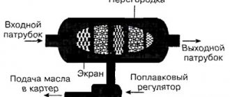
Figure 212. Structure of the dryer
Air dehumidification in the discharge phase.
The air supplied by the air compressor passes through the supply inlet 1 (the pneumatic circuit is shown in Figure 214) first through the ring filter (12), where it is pre-cleaned from contamination such as carbon deposits and oil. In addition, the air is cooled in the ring filter (12) and part of the moisture contained in it is collected in the moisture separation chamber (9). The air then passes through the granular powder (13) - where dehumidification occurs - to the check valve (10); opens it and passes through outlet 21 to the air receivers of the brake system. At the same time, through the jet (11) and outlet 22, a small air receiver (14) is filled for regeneration. Air purification and preliminary removal of moisture in the ring filter (12) has a positive effect on the service life and efficiency of the powder (13).
Air regeneration in the cleaning phase.
When the pressure in the brake system rises to an appropriate level, the so-called cut-out pressure, the integrated pressure regulator opens the relief valve (8). The air pumped by the air compressor and the compressed air from the air dryer are released into the atmosphere through the outlet (7) and the atmospheric outlet 3, while capturing the accumulated moisture, oil and most of the dirt particles settled in the filter.
Dry air from the regeneration air receiver (14) passes through outlet 22 and nozzle (11) and fills all free space. Penetrating through wet powder granules (13), air absorbs moisture deposited on the surface of the granules before being released into the atmosphere through the ring filter (12) and the discharge valve (8).
The check valve (10) prevents the reverse flow of compressed air from the air receivers.
Noise reduction.
Thanks to the integrated silencer (6), the noise generated when the dump valve (8) opens is significantly reduced. In this case, a multi-stage throttle muffler is used, the design of which protects against high-speed pressure pressure, which can cause contamination and thereby weaken the efficiency of the air dryer.
Operation of the integrated pressure regulator.
Due to the pressure in the receiver, the control piston (2) moves and the air passes through the channel (4). As soon as the pressure reaches the cut-out pressure, the control piston (2) moves to the right and opens the outlet (3). In this case, the control piston (2) closes the inlet (1) leading to the ventilation hole, no leakage occurs. As a result, compressed air is supplied through the channel (5) to the relief valve (8), opening it. As soon as the receiver pressure drops to the cut-in pressure level, the spring of the control piston (2) forces it to move to the left, thereby opening outlet (1) and closing outlet (3). The air above the exhaust valve (8) exits through the channel (5), inlet (1) and vent (15); the cleaning valve closes.
The shut-off pressure and excess pressure of the regulator are determined by the spring load and the movement of the control piston. Both values are achieved - largely independently of each other - by means of the adjusting screw 15.
Safety valve.
In the event of a malfunction, the pressure regulator, the safety valve - consisting of a relief valve (8) and a valve compression spring (7) - ensures that the pressure in the receiver is limited, releasing the incoming air to the atmosphere as soon as the pressure reaches the opening pressure (emergency pressure).
Heater operation.
To prevent freezing of the relief valve (8) under unfavorable weather conditions, use an electric heater installed in the air dryer body at the location of the relief valve (8) (not shown in the figures). The heater is turned on from the ignition switch, the temperature is controlled by an automatic built-in thermostat. Various modifications of the heater are possible. The heater is shown in Figure 213.
Figure 213. Appearance and internal structure of the heating element
When the ignition switch is turned on, the heating is controlled by a reverse current thermal relay. To prevent the battery from being discharged when the vehicle is parked, the heating current must be turned off when the ignition switch is turned off. The heater can be built in additionally.
Installation.
General instructions.
Installing an air dryer increases the volume of the brake system (volume of the air dryer plus the regeneration air receiver). This increases the filling time of the brake system by approximately 3% to 7%. It is therefore necessary to check whether the permissible filling time of the brake system is being maintained.
In addition, the average duty cycle of the pressure regulator when installing an air dryer should not exceed 50%, since if the pumping time is increased, there may not be enough time for regeneration. At a duty cycle of 50% to 60%, it is not possible to install an air dryer.
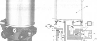
The installation location of the dryer in the vehicle brake system is shown in Figure 214.
Regeneration air receiver parameters.
When installing the regeneration air receiver, the following must be taken into account:
— volume of air receivers of the brake system;
— excess pressure of the pressure regulator;
— pressure regulator shut-off pressure;
— average operating cycle of the air compressor before installing the air dryer.
The diagram can be used to determine the parameters of the regeneration air receiver at the general values of cut-off pressure and total system volume (shown in Figure 215). Recommended regeneration receiver for an average duty cycle of 40% and overpressure = 1 bar.
Connecting pipeline.
To connect an air compressor to an air dryer, and an air dryer to a four-circuit safety valve, a 18x1.5mm pipeline is recommended. The length of the air compressor pipeline depends on the permissible air temperature of the inlet in inlet 1. Typically, a pipeline with a length of 4 to 6 meters is used. To avoid water accumulation, this pipeline must be positioned with a constant slope towards the air dryer. To protect the air dryer from vibration of the air compressor, the discharge pipe is made flexible, and it must be resistant to high pressures.
Several versions of air dryers are provided with drain pipes at atmospheric outlet 3 to drain accumulated condensate. However, it is necessary to take into account the higher sound level during shutdowns. Sound reduction can be achieved by using a longer hose or a separate muffler on the hose.
For all noise reduction measures, it is necessary to ensure a dynamic pressure on inlet 1 that does not exceed 0.25 bar during the pressure release phase (regeneration phase). Therefore, the location for installing the air dryer must be selected so that it is possible to install a device with an integrated muffler, without an outlet pipe at atmospheric outlet 3.
Figure 214. Location of the dryer on the vehicle pneumatic circuit
Additional installation instructions.
Before installing the air dryer, the following conditions must be met:
-The air dryer must have a cut-off pressure and excess pressure the same as the previously used pressure regulator (or according to calculations).
— It is necessary to remove the previously used pressure regulator;
-Remove or turn off automatic condensate drain valves and antifreeze devices.
-The air dryer is installed between the air compressor and the multi-circuit safety valve. Allowable tilt in any direction from 0° to 90°, atmospheric outlet 3 can point down or to the side.
-The air dryer must be installed at a sufficient distance from heat-emitting parts of the engine, exhaust system or drive.
-There must be sufficient free space for replacing the desiccant cartridge.
-To secure the air dryer body, three threaded holes M12x1.5 with a depth of 20 are provided.
In rare cases, due to air vibration during the pumping phase, popping noises occur, which can be eliminated by the following measures.
-Change the length of the pipeline between the air compressor and the air dryer, taking into account the permissible temperature of the compressed air at the inlet of the air dryer.
- Install a damping receiver (from 1 to 1.5 liters) behind the air compressor and in front of the dryer.
Figure 215. Dryer parameter diagram. Designations: 1 - Pressure regulator cut-off pressure (bar); 2 — Total volume of the brake system (liter); 3 — Regeneration receiver 4 liters; 4 — Regeneration receiver 5 liters; 5 — Regeneration receiver 7 liters; 6 — Regeneration receiver 9 liters
Using the condensate drain valve.
To regularly check the effectiveness of the dehumidification, it is necessary to install at least one condensate drain valve in the air receiver behind the air dryer. In brake systems with different pressure levels, the condensate drain valve is installed in the receiver with the maximum pressure.
Service.
If compressed air leaks, the duration of the filling phase increases, which has an adverse effect on the air drying process. Therefore, if an air leak is detected, repairs must be started immediately.
If an air dryer was included in the brake circuit of a used vehicle, the results of the upgrade can only be felt after three weeks of operation, since any moisture in the brake system is mixed with oil and is therefore removed slowly.
The service life of the replacement drying cartridge depends solely on the degree of contamination of the incoming air. In most cases, depending on the amount of oil in the supplied air, it is enough to replace the replacement cartridge after 1-2 years; for Russian conditions, the recommendation is to replace it 2 times a year (summer-winter and winter-summer cycles).
Replacing the dryer cartridge is carried out according to the following scheme.
-Clean the surface of the air dryer from dirt.
-The air dryer must not be under pressure. This can be achieved by filling the system with compressed air before turning off the pressure regulator or loosening the threaded connection on inlet 1.
-Unscrew the drying cartridge by turning it counterclockwise (you can use a special key).
-Clean the surface of the housing with a rag; under no circumstances should dirt get into the cavity of the purified air (check valve 10).
-When replacing, use only a new cartridge.
- Lightly lubricate the seals.
-Tighten the new drying cartridge by hand (tightening torque approx. 15 Nm).
-Removed (used) drying cartridges must be disposed of separately, since the cartridge contains settled oil.
Checking the safety valve.
To check the safety valve (shown in Figure 216), the pressure regulator is turned off by tightening the hollow screw 2 until it stops. At pressure “A” on pressure gauge 1, the dryer outlet valve should open. During the switching interval, the exhaust valve must be tight (check diagram shown in Figure 217).
Figure 216. Safety valve
Checking the check valve.
When the pressure drops to 0 bar on pressure gauge 1, the pressure on pressure gauge 2 should remain the same.
Setting the pressure regulator.
Set the setscrews 1 and 2 to dimensions 43 and 57 mm. respectively.
Fill the receiver to the specified cut-off pressure “B” according to pressure gauge II (for adjustments, see the tables in the dryer data sheet). Tighten screw 2 until it stops, and then unscrew it 1.25 turns. During further adjustment, it is not allowed to tighten this screw by this amount. Turn screw 1 out until the outlet valve opens and lock in this position.
Figure 217. Dryer test diagram
By reducing the pressure in the receiver (pressure gauge II), the switching interval “C” can be determined. If the switching interval is long, then it is necessary to unscrew screw 2 (to the left). If the switching interval is short, screw 2 should be turned (to the right). After tightening the locknuts, the adjustment of the regulator must be checked again and, if necessary, adjusted again.
Checking the regeneration process.
Fill the regeneration cylinder (4 l) to the cut-off pressure “B” on pressure gauge III. When opening the air dryer outlet valve, turn off the compressed air supply. The pressure in the regeneration receiver should drop to 1 bar within “D” seconds.
Checking for leaks.
When air is supplied to terminal 1 with pressure “B”, a maximum leakage of 10 cm/min is allowed.
KAMAZ water separator: device, principle of operation, purpose
Cars November 29, 2016
A compressor is installed on all Kama-made trucks. KamAZ 5320 is no exception. This element not only pumps air, but is also a source of oil and moisture accumulation in the system. Therefore, for its normal operation, an additional moisture separator (KAMAZ) is installed. The principle of operation, its structure and varieties are further in our article.