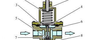
The dryer is installed after the compressor. Tubular and adsorption devices are used in trucks. Devices of the second type are more efficient. Dryers consist of:
- Heater;
- Pressure regulator;
- Silencer;
- Patrona.
The main elements are located in the cast valve body of the MAZ 5440 air dryer.
The main components of the device provide control of the pneumatic system. The housing contains safety and check valves. On the surface there are fittings and pipes.
The MAZ dehumidifier has a heater. At temperatures below +5 degrees, the device maintains the microclimate necessary for the adsorbent. The heater prevents the water in the system from freezing.
Protects against tears and deformations. There is a connector on the housing to connect the heating element. A muffler is installed at the bottom to eliminate unpleasant noise.
A drying cartridge is fixed in the upper part. The spare part is used to remove moisture from incoming air. The cartridge contains a cylindrical container with an adsorbent. The part is installed on the filters. It is pressed from above by a spring. There is a threaded hole at the bottom of the cartridge.
Adjusting the WABCO air pressure regulator
- __/catalog/__
- __/catalog/tehinfo/__
- __/catalog/tehinfo/kpp-kamaz/__
- __/catalog/tehinfo/kpp-kamaz/epp-kpp/__
Adjusting the three-position gear shift sensor
Adjustment of the three-position gear sensor 2 (see Fig. 140) is carried out when assembling the IMCP. In operation, the need to adjust the sensor arises when replacing it.
To adjust the sensor, it must be installed so that the distance between the planes G and D is equal to 40.5. 41.5 mm (for KAMAZ -142 or YaMZ-236 gearbox) and 39.0. 39.5 mm (for gearbox type SAAZ-695).
Adjusting gear selection sensors
For gearboxes , adjustment of gear selection sensors 3 (see Fig. 139) is carried out when assembling the IMCP at the manufacturer with gaskets between the sensor and the IMCP body. The thickness of the gaskets should be equal to 7.1 mm minus the distance from the end plane A of the rod rack to the plane B of the sensor with the central location of lever 6.
For other gearboxes, sensor adjustment is not provided.
Adjusting the actuator cuffs
Adjustment of the tightening force of the screws securing the cuffs of the piston riders of the gearbox actuator is carried out when assembling the IMC.
In operation, this adjustment is made in accordance with the timing of maintenance (see paragraph 6 of the manual) or as necessary in the event of a leak in the cuffs. A sign of the need to adjust the cuffs is that an air-oil emulsion begins to eject from the gearbox breather (the formation of oil stains around the breather is allowed), since if the seals of the cuffs are broken, air under pressure begins to enter the gearbox housing.
To adjust the fastening screws 23 (see Fig. 139) of the cuffs 19 of small pneumatic cylinders of the IMCP, you must:
- remove gear selection sensors 3;
- tighten screws 23 symmetrically relative to the center of the piston-rider 9 with a torque of 2.3-2.5 kg-cm (0.23-0.25 N-m);
- Reinstall the gear selection sensors.
To adjust the fastening screws 23 (Fig. 140) of the cuffs of large IMCP pneumatic cylinders, you must:
- remove covers 14 (assembled with sensor 2) and 27;
- tighten screws 23 symmetrically relative to the center of the piston-rider 11 with a torque of 3.1. 3.5 kg-cm (0.31. 0.35 N-m);
- replace covers 14 (inductor 15 should fit into the hole in sensor 2) and 27;
Design features of Lawn Next since 2014
Typically, users of our site find this page by the following queries: no Lawn Next brakes, bleeding Lawn Next brakes, Lawn Next brake system diagram, Lawn Next brake system repair, Lawn Next brake system malfunctions
Design Features
The car is equipped with a WABCO braking system with a pneumatic dual-circuit drive and disc brakes on all wheels, an anti-lock brake system (ABS) and a brake pad wear warning system.
The role of the reserve system is performed by the brakes of the front and rear axles.
The parking brake system acts on the disc brakes of the rear wheels due to spring energy accumulators and is operated by a manual crane installed in the cab.
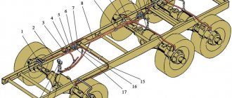
Diagram of the car's working brake system:
- alarm indicator for emergency drop in air pressure;
- pressure gauges;
- anti-lock brake system (ABS) indicator;
- parking brake indicator;
- compressor;
- air preparation module;
- receivers;
- receivers;
- receivers;
- emergency air pressure drop sensor;
- pressure gauge sensor;
- reverse acting brake valve;
- noise suppressors;
- pedal brake valve;
- control outlet valves;
- modulator;
- power sensor (STS);
- two-way valve;
- quick release valve;
- brake chamber:
- brake chamber with spring energy accumulator;
- ABS sensor;
- ABS sensor;
- ABS rotor;
- ABS rotor;
- ABS electronic unit;
- pad wear limit sensors;
- pad wear indicator
- noise suppressors;
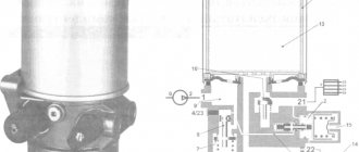
Air preparation module
An air preparation module is installed in pneumatic brake systems to dry and purify the air coming from the air compressor, to regulate the operating pressure in the brake system, as well as to divide the supply line into two main and two additional circuits, with automatic shutdown of the circuit in case of damage and maintaining a supply of compressed air in undamaged circuits.
Maintenance of the air preparation module consists of replacing a replaceable drying cartridge, the service life of which depends only on the degree of contamination of the incoming air. The replacement cartridge must be replaced after one year.
Drying cartridge:
- cartridge;
- sealing ring
The dryer cartridge is replaced in the following order:
- Clean the surface of the air dryer from dirt.
- The air dryer must not be under pressure. This can be achieved by filling the system with compressed air before turning off the pressure regulator or loosening the threaded connection on the air supply fitting.
- Unscrew the drying cartridge by turning it counterclockwise.
- Clean the surface of the housing with a rag; under no circumstances should dirt fall into the cavity with purified air.
- When replacing, use only a new cartridge and O-ring.
- Lubricate the seals with a thin layer of CIATIM-221 lubricant.
Air dryers for pneumatic systems of trucks and buses
The pneumatic system of trucks and buses is responsible for braking, suspension control, door opening and closing devices, clutch and other units. It consists of a number of installations and devices: compressor, pressure regulator, receivers, pneumatic actuators, sensors, air valves.
The pneumatic system also includes an important unit - an air dryer. It is designed to remove moisture as much as possible from the air flows coming from the compressor.
Unprepared air, with a large amount of water vapor, can reduce the service life of system units or completely damage them: moisture condenses on the inner surface of the walls of metal parts, causes corrosion, crystallizes at subzero temperatures, turns into ice, which leads to failure of pressure regulators air (RDV) and brake valves. as soon as the air pressure in the brake circuit drops below the set level, the energy accumulators are activated, the car’s brakes immediately “unlock”, and it stops moving until the fault is eliminated. This, in turn, leads to unscheduled repairs (often by a mobile crew) and disruption of commercial flights.
Therefore, removing moisture from the air is a priority measure to preserve the “health” of the pneumatic system of a truck or bus. Practice shows that a severely neglected pneumatic system often cannot be finally brought back into working order even by the most talented mechanic.
The Hottecke brand produces adsorption dehumidifiers for trucks and buses. You can order them in our partner stores.
Hottecke adsorption dryers
Two types of dryers can be installed in KAMAZ, MAZ trucks, PAZ, LiAZ buses:
- Tubular moisture-oil separators;
- Adsorption.
Moisture-oil separators are inferior to adsorption dryers in terms of productivity and compactness, and are gradually being replaced by them.
General characteristics of the braking system
The Wabco semi-trailer brake system consists of high quality materials. Spare parts undergo mandatory testing.
Advantages of Wabco brakes:
- keep the loaded trailer in a safe position during stops;
- slow down vehicles without sliding as much as possible;
- optimize braking distance;
- have functional air suspension;
- installed on all types of trailers and semi-trailers;
- capable of conducting intelligent analysis of information and then converting it into functions, of which there are more than 40.
Wabco auto parts are numbered. An example is shown in the figure.
WABCO brake system.
The numbers consist of 10 digits (in the figure they are labeled 2,3,4).
- The numbers indicate the date of manufacture.
- Six digits determine the type of device.
- Indicates an option.
- Indicates the condition of the spare part.
In the picture, the condition of the spare part is indicated as 0. The number indicates that the part is new.
Here are the values for other numbers that can be specified instead of 0:
- 1 – the device is new, but not completely, but only part of it;
- 2 – indicates a repair kit or assembly unit;
- 4 and 7 – accessories and spare parts, respectively.
The numbers 001 in the figure indicate the original part number.
Components
Wabco brakes consist of:
- Wabco semi-trailer brake valve. Provides pneumatic and electrical signals that correspond to the required deceleration value;
- Wabco control unit. Controls the brakes;
- acceleration valve. Regulates pressure in the front axle;
- braking unit. It is a combination of a brake valve, a control unit and a proportional accelerator valve;
- semi-trailer brake control valve. Regulates the pressure output at the locations where the connection heads are located;
- pressure regulator. Controls the force of air pressure in the pneumatic system.
Principle of operation
Wabco produces two types of brake systems for semi-trailers:
- EBS;
- ABS.
Wabco's EBS brakes are electronically controlled.
EBS brakes.
The operating principle is as follows:
- The electronic unit is responsible for the entire system. The main signals are sent from it.
- On the brake cylinders in the valves, the pressure indicated by the signals is reached.
- Speed sensors regularly provide wheel speed data to the EBS system.
- In the event of failures at the same time, all valves function as if a conventional pneumatic system was used. After which the reserve pressure begins to operate in those brake cylinders where the pneumatic system is located, but with some delay.
- The pneumatic system cannot operate simultaneously with the load sharing valve. For this reason, a certain amount of compressed air exerts resistance, thereby creating a strong braking force on the rear axle.
- In this case, the spare valve stops the operation of the pneumatic system in the rear cylinders on the axle.
- Under such conditions, EBS functions quietly and is not disinhibited.
EBS is also equipped with other brake control processes that can detect any deviations.
The manufacturer has created an ABS system called Vario Compact, or VCS, specifically for towed vehicles.
Principle of operation:
- At the start of a move, while driving or when stopping, the ABS is tested by the main operating processes.
- These processes transmit a signal to the driver that there is some kind of malfunction through the control lamp.
- If necessary, the functional system disables ABS and individual components.
- In this case, the effect of the normal brakes is maintained, but the effect of the anti-lock device is limited or lost.
- Power transistors receive the signals and then transmit current to the magnetic valves.
- The magnetic valve is activated and in milliseconds increases, decreases or maintains the operating pressure in the brake cylinders (regardless of the pressure created by the air distributor), due to which braking is carried out.
Scheme
There are two versions of Wabco's EBS: APAC and Standard. Here are the operating diagrams for each.
Diagram of the EBS3 "ARAS" system (4S/4M configuration)
System diagram EBS3 “Standard”/configuration 6S/6M
ABS brake systems also have two versions C and D.
ABS/ASR (version C)
ABS/ASR (version D)
Malfunctions and repairs
In some cases, repairs may be required; malfunctions may be caused by leaks in the brake system. The device stops automatically removing moisture and condensation. In this case, the O-ring and springs may need to be replaced.
Troubleshooting procedure:
- Remove the bracket using a wrench.
- Unscrew the fasteners from the radiator dryer.
- Carry out an external inspection of the O-rings and clean the surface of the air dryer. If necessary, replace worn elements.
- Remove the screws of the drive cover.
- Separate the cover from the body and replace the gasket.
- Remove the thrust ring and lock washer.
- If the membrane of the sealing ring mechanism has lost its seal, replace it with a new one.
- If air constantly hisses from the drain hole, replace the cuffs by removing the thrust washer from the rod.
- Check the condition of the bypass valve and spring for wear.
All repair work must be carried out by placing the vehicle on a special platform and turning off the power unit.
The price for repairing a moisture separating device ranges from 1000 to 2000 rubles.
Malfunctions
Breakdowns occur in any technology. Wabco brake systems can detect them quickly. Especially if the trailer is connected to EBS. The system is capable of self-testing and detecting faults.
Signs
You can see the breakdown by the following signs:
- continuous operation of the air compress, during which air is constantly pumped into the system;
- lit buttons on the dashboard that indicate problems;
- strange knocking in brakes and tires, squeaking;
- untimely braking;
- the tendency of vehicles to skid when braking.
Reference! The yellow button means limited control of the system, and the red button means the EBS is partially connected, its operation has slowed down and dropped below acceptable limits.
Causes
The appearance of one of the above symptoms indicates that the Wabco system has failed. At this stage, it is important to find the cause of the breakdown.
There may be several of them:
- failure of EBS or ABS;
- improper operation of transport;
- self-repair (for example, some try to repair the brakes on a Schmitz or Krone trailer, reading advice from various forums);
- lack of regular maintenance.
Troubleshooting
Repairs must be carried out only at specialized service stations. Troubleshooting yourself may damage the system even more.
Lack of technical inspection and untimely repairs lead to:
- emergency situation in case of brake failure, increasing braking distance;
- brake failure;
- malfunction of electronics.
Specialized service stations offer:
- diagnostics of faults in trailed ABS, ESB, pneumatic braking systems from Wabco;
- repair of the brake release valve;
- searching for faulty sensors;
- search for non-working semi-trailer cranes;
- setting braking parameters;
- firmware of a working TABS-E WABCO modulator, etc.
Operating rules
In order for the air regeneration device to function without failures, it is necessary to carry out timely maintenance in accordance with the user manual. It is also recommended to inspect the device daily for damage and defects.
In order to check the safety valve of the equipment, you need to tighten the hollow screw of the regulator until it stops. If the mechanism is working properly, then at pressure “A” the outlet valve will open, which must be sealed during the switching interval.
The check valve is serviced using a pressure gauge. If the pressure level drops to 0 bar, it is necessary to disassemble the mechanism and check the integrity of the parts.
Design and principle of operation
The Wabco water separator is a filter equipped with an electric drive. The device starts automatically as soon as the ambient temperature drops to +6-7°C. As soon as the indicator in the brake system stabilizes, the device turns off. The adsorption granules are contained in a replaceable filter, which must be periodically blown out with compressed air for maximum performance.
Structurally, the dehumidifier consists of the following elements:
- cast body into which a glass with adsorbent is placed;
- primary and secondary dirt filter;
- pressure regulator;
- valve group;
- body heater;
- muffler (“mushroom”);
- supply inlets;
- drying cartridge.
All the main elements of the dehumidifier are located inside the housing; they are responsible for the performance and efficiency of the unit. Externally, the device resembles an oil filter.
The operating principle of the moisture separator is extremely simple. Air from the compressor is directed into the housing, enters the cartridge through the channels and passes through the adsorbent. This is where 90% of the condensate settles. Dirt filters retain mechanical suspensions. After this, dry air is directed to the pressure regulator and enters directly into the system.
As it is used, the moisture level in the adsorbent increases and the filter loses performance. Before the resource exhaustion period expires, the device is regularly regenerated. Backflushing is carried out so that excess moisture comes out through a special valve. Regeneration is accompanied by increased noise, so the unit is equipped with a muffler.
At ambient temperatures of +6...+7°C, the housing heater on the dehumidifier automatically turns on. This ensures a constant positive temperature of the adsorbent, in order to prevent freezing of the liquid in the granules, which can lead to rupture of the device. To connect to the KamAZ electrical network, a special connector is provided on the dryer body. The device is installed immediately after the compressor, on the right side member of the frame.
Air suspension dryer WABCO
After a discussion in the “air suspension”, I decided to assemble it on the basis of a silica gel desiccant; the simplest (perhaps the most correct) was proposed to use a standard compressor from brand suspensions, because it contains a desiccant and a pressure regulator, etc.
But its price and the fact that the compressor was already available prompted the desire to adapt a standard dehumidifier from a truck for air preparation.
I bought a WABCO desiccant cartridge, it turned out to be a very large piece of crap...
There were two options for installing it:
- The standard system is from a truck, but its dimensions are slightly smaller than the cartridge itself, and it was not possible to find it at a disassembly site for less than 4000 rubles, and it is in terrible condition, and a new one generally costs around 16-30...
- Carve the base yourself.