11/10/2020 Air and working fluids in MTZ tractors are purified using filters. These parts are capable of separating heterogeneous media, which consist of solid, liquid, and gaseous components. The main part of the purifier is a filter element made of a special material: in DIFA filters, this is usually paper with special impregnation. The filter element traps dust, dirt, small metal particles and other foreign matter, thereby preventing clogging and failure of the main mechanisms.
MTZ tractor air filter
The device is mounted in front of the power unit and passes the entire flow of sucked in external air through itself, cleaning it from dust, microorganisms, moisture and redirecting it into the combustion chamber. The website presents air filters that are suitable for installation on MTZ 80, 82, 320 models: DIFA 4332, DIFA 4337.
Taking into account the fact that tractor air filters always operate in highly dusty conditions, their surface must be periodically inspected. Damage or excessive contamination of the air filter can be suspected by such signs as a noticeable increase in fuel consumption and a decrease in engine power level.
If the purifier is heavily contaminated, but has not yet exhausted the service life established by the regulations, the filter element is removed from the housing and purged with compressed air. The body part is washed from the inside with diesel fuel or hot water, and the filter element is thoroughly dried before installation.
The air filter on MTZ tractors is replaced at every maintenance, the frequency of which is indicated in the operating manual.
Our work on Instagram
gidroremont_en
Excavator boom bushing
Hydraulic cylinder 190. 140. 1600
Rotary gear carrier
Replacing the hydraulic cylinder “sleeve”
More work...
Fuel filters for MTZ tractors
Tractor equipment is equipped with two types of cleaners: coarse cleaning (FGO) and fine cleaning (FTO). We offer the following models of fuel filters suitable for MTZ agricultural machines: DIFA 5114, DIFA 5125.
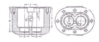
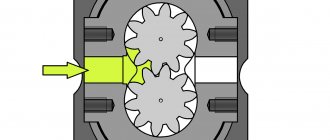
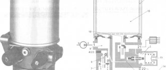
The coarse fuel filter consists of two main elements: a reflector and a brass mesh, which acts as a filter material. The reflector and mesh are located inside the metal housing. In addition to these components, the CSF includes:
- vibration damper;
- distributor;
- sump for draining water;
- pad;
- pressure ring.
Two tubes are connected to the MTZ coarse filter: through one of them, fuel enters the purifier body, through the second, purified fuel is discharged.
FGO separates flammable material from large and medium-sized polluting particles, water and paraffins. When the coarse filter is clogged, the quality of the fuel supply deteriorates and engine power decreases.
The structure of the MTZ fine fuel filter includes several filter elements connected to each other by metal frames. The function of filter material in DIFA fuel purifiers is performed by special paper impregnated with resins. FTO traps small particles present in the fuel that have passed through the structure of the coarse cleaning device.
In different models of tractors, FGO and FTO are represented by different elements, but sometimes their function is performed by a single fuel filter.
According to the regulations, replacement of fuel filters on MTZ tractors must be carried out at every maintenance-2. These parts are changed unscheduled in case of critical contamination, which is most often caused by low-quality fuel. The faulty state of fuel purifiers is indicated by:
- drop in power of the power unit, so-called engine tripping;
- stopping the engine for no apparent reason when idling;
- failures in the operation of the internal combustion engine, which appear as the speed increases.
Locksmith assistant
Filling and checking the oil level.
When working with hay throwers and dump trailers, add oil to the hydraulic unit housing to the level between the “P” and “C” marks on the oil gauge. When using other agricultural machines, set the oil level between the “O” and “P” marks. Check the level and fill the oil into the body of the hydraulic units when operating tractors with machines with single-acting cylinders, with the rods fully retracted.
Cleaning the oil filter (mesh) and breather.
Perform these operations for the first time after running the tractor for 30 hours, and then every 1000 operating hours. To wash the filter (standard cabin):
a) fold the diesel engine cover forward;
b) remove dust and dirt from the tank cover,
c) unscrew the bolts securing the filter cover 11 (Fig. 1);
d) if necessary, use a clamp to disconnect the drain hose from the lid fitting,
e) remove the filter assembly together with the housing so as not to pour the dirt in it into the tank;
f) thoroughly rinse the filter elements 5 with gasoline or diesel fuel;
g) assemble and install the filter in reverse order;
h) simultaneously with washing the filter, unscrew the breather plug 13, remove the foam padding, rinse it, squeeze it out and put it in place.
Maintenance of the hydraulic oil tank filter with a replaceable filter element. Replace the filter element after running in the tractor and then every 500 operating hours (TO-2). To replace the filter element (unified cabin), do the following (Fig. 2):
1) unscrew bolts 1 securing filter cover 2 to filter bowl 12;
2) remove cover 2, spring 3 and stop 4, fixing the filter in the oil tank;
3) remove the filter assembly, holding it by the hexagonal nut-bushing 5;
4) lock the tube 11 and unscrew the hexagonal nut-bushing 5, remove in sequence the limiter 6, the sealing ring 7 and the filter element 8;
5) wash body 9 and tube 11 in a washing solution;
6) install a new filter element 8 and assemble the filter;
7) insert the filter assembly into the oil tank and mount the parts previously removed from the oil tank.
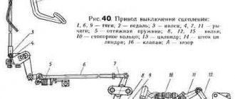
Adjusting the engagement of the hydraulic pump drive gear.
If the hydraulic pump drive gear is not fully engaged or when it is replaced, it becomes necessary to adjust the gear engagement. The adjustment is made in the following sequence:
a) install handle 1 (Fig. 3) for turning on pump 5 in the lower groove of plate 2 (pump off position);
b) loosen the bolts securing the plate to the tank and start the diesel engine;
c) rotate the handle with the plate at low engine speeds upward until the gears audibly touch, then move the handle down a little and secure the plate with bolts.
Adjusting the locking mechanism of the control levers of the GSV and the distributor.
Check the correct adjustment of the locking mechanism as follows:
a) set the GSV handle to the “pressure release” position, while the distributor handle should automatically move and remain in the “lift” position;
b) set the GSV handle to the “GSV off” position, and the distributor handle to the “floating” position. The GSV handle should not move upward from the “GSV off” position under the action of the plate. If these conditions are not met, adjust the length of the rod that controls the main cylinder spool.
Adjustment of force (positional) regulation mechanisms.
Adjust the control sector as follows:
a) move the handwheel-limiter 1 (Fig. 4) along the sector slot forward (along the tractor) until it stops at the edge of the slot;
b) check and, if necessary, ensure easy, free movement of control handle 4 along the sector when turning it forward (along the tractor);
c) check and, if necessary, ensure clear return of the regulator control handle from the “lift” position to the “regulator off” position to lock 3. Sticking of the handle in intermediate positions is not allowed, as it can cause excessive heating of the oil in the hydraulic system when operating the tractor;
d) loosen the bolts 5 securing the sector and turn it forward until it stops against the bolt with the edge of the adjustment groove;
e) turn the regulator handle forward until it stops against the handwheel-limiter;
f) turn the handle 4 of the regulator “towards you” along the sector until the internal spring of the regulator begins to compress to select the clearances in the control. Holding the handle in this position, move sector 2 until the handwheel-limiter stops in handle 4 and in this position of the sector, securely fasten it with bolts;
g) ensure clear fixation on the teeth of the sector, as well as the possibility of convenient installation of the handle in the desired position by tensioning the spring of the locking device 6.
On a tractor with a unified cab, adjust the governor control as follows (Fig. 5):
1. Remove the side console cover.
2. Adjust the length of the rod 5 so that when moving handle 1 back (along the tractor) a gap of 18-24 mm is formed between the rubber roller 4 on this handle and the edge of sector 3.
Adjust the position rod as follows:
a) loosen the lock nut on the adjusting coupling 17 of the rod 7 (Fig. 6)
b) set switch 2 to the middle position;
c) lift the attachment to its highest position;
d) move position rod 7 forward (along the tractor) until the longitudinal groove at the end of rod 7 stops with pin 11 on lever 12;
e) change the length of the rod with the adjusting coupling 17 so that the switch 2 with its protrusion fits freely into the groove of the position lever 3, then shorten the rod 7 by 1/2 turn.
Adjust the force sensor as follows:
a) set switch 2 (Fig. 6) to the middle position;
b) remove the central link 16 of the hitch, install the central link pin 14 on the upper hole of the earring 15;
c) using an additional lever, create a tensile force of about 400-500 kgf in the direction of arrow “B”, ensuring that the shackle rotates all the way and compresses springs 19. After removing the load from the lever, the shackle should return to its original position, while the sensor stroke, measured according to the movement of power rod 8 must be at least 11 mm;
d) after making sure that the sensor is in good condition, unspread the castle nut 18, tighten it until the sensor springs begin to tighten, then tighten it an additional 1/2–1/3 turn until the slot in the nut coincides with the hole for the cotter pin and tighten it.
Adjust the power traction after adjusting the power sensor:
a) loosen the lock nuts on the adjusting coupling 4 of the rod 8 (Fig. 6);
b) set switch 2 to the middle position;
c) using an additional lever, create a force to ensure that the earring rotates to its extreme position (in the direction of arrow “B”);
d) holding the lever in the depressed position (in the direction of arrow “B”), try to insert the protrusion of switch 2 into the groove of power lever 1. If this fails, change the length of rod 8 with clutch 4 so that switch 2 with its protrusion fits freely into the groove of the power lever 1;
e) shorten the rod by rotating clutch 4 by 1/2 turn;
f) secure the coupling with 4 nuts.
When an agricultural implement is mounted on a tractor, the use of a special additional lever is not required. To adjust the power draft in this case, it is enough to lift the implement above the surface of the platform on which the tractor stands, while the mass of the implement will create the necessary tensile force on the power sensor through the central link. It should be remembered that in this case the central link must be installed on the upper hole of the hitch link. Raise the implement only until it is off the ground.
Source Newspaper “Avtodvor”
February 2013