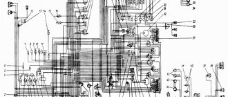
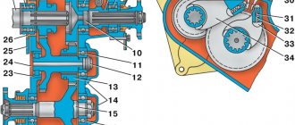
Transfer case: 1 – drive shaft (secondary shaft of the gearbox); 2 – bearing of the drive shaft (secondary shaft of the gearbox); 3 – drive gear (gear for direct and downshift gears); 4, 7 – rear axle drive shaft bearings; 5 – speedometer driven gear; 6 – speedometer drive gear; 8, 21 – cuffs; 9, 22 – flanges; 10 – rear axle drive shaft; 11, 23 – intermediate shaft bearings; 12 – intermediate shaft; 13 – gear for engaging the front and rear axles; 14 – bearing caps; 15 – front axle drive shaft; 16, 20 – front axle drive shaft bearings; 17 – crankcase cover; 18 – crankcase; 19 – drain plug; 24 – plug; 25 – suspension plate; 26 – thrust cup of the bearing; 27 – hatch cover; 28 – cover of the switching mechanism; 29 – fork rod for direct and downshift gears; 30 – front axle fork rod; 31 – locking ball; 32 – retainer spring; 33 – front axle shift fork; 34 – forward and downshift fork
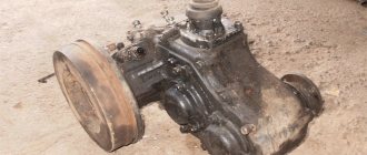
The transfer case is two-stage, mechanical, and has an additional reduction gear (Fig. 3.49).
Some vehicles can be equipped with a modernized “small-module” transfer case, in which the gear teeth of the front and rear axles, as well as the toothed rims of the rear and front axle drive shafts, are made with a 2.5 mm module (instead of 3.5). At the same time, the low gear ratio decreased and became 1.47 (instead of 1.94).
The transfer cases are interchangeable and look no different. The modified parts differ from similar parts with a 3.5 mm tooth module in the number of teeth
Maintenance
During operation, check the oil level and replace it within the time limits specified in the lubrication table. Check all fastenings periodically. If a leak is detected, find out the cause and replace the faulty parts (gaskets, cuffs, plugs, etc.).
During vehicle operation, it is possible to lower the oil level in the gearbox to 8 mm relative to the lower edge of the filler hole and simultaneously increase it in the transfer case. In this case, it is not necessary to equalize the oil levels in the gearbox and transfer case, since the total volume of oil ensures the normal operation of both units.
When changing the oil in the transfer case housing or topping it up, it is necessary to simultaneously bring the oil level in the gearbox to the lower edge of the filler hole.
On vehicles of the UAZ-31512 family, lubricate the shift lever axle through a grease nipple. Access to it is from below.
On vehicles of the UAZ-3741 family, when disassembling the control mechanism, lubricate the shafts and lower support, and also adjust the front linkages of the mechanism. The transfer box has no adjustments.
Repair of UAZ Bukhanka transfer case
Serious repairs to the UAZ transfer case are rarely performed. As a rule, to restore normal operation, adjusting the product and lubricating problem areas is enough. If repairs cannot be avoided, then the operation to return the box to its former functionality is done in strict order.
Manipulations performed:
- Dismantling the transfer case;
- Disassembling the transfer case;
- Fault detection;
- Troubleshooting (replacement, restoration of parts);
- Transfer case assembly;
- Installing the transfer case in place;
- Functionality check and configuration.
Disassembling the box:
Before carrying out work, select the necessary tools; for this, find out the type and type of transfer case. Functionally, repair is the replacement of damaged parts with new ones, for this reason more attention is paid to the rejection stage.
Subject to replacement:
- Oil seals (changed during disassembly, regardless of the degree of wear);
- Gears (parts cannot be repaired due to the loads they experience);
- Forks and splines (elements affect the quality of work and safety);
- Bearings;
- Protective casing (if cracks or chips are detected, the part is replaced).
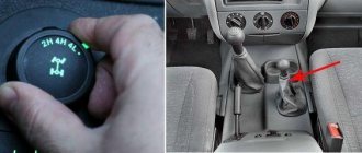
UAZ transfer case control mechanism:
Disassembling the transfer case
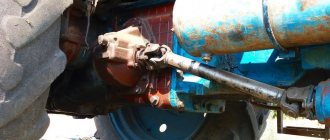
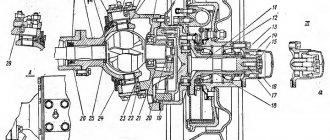
Disassemble the transfer case in the following order: 1. Unscrew the nuts and bolts securing the transfer case to the gearbox and disconnect the components. Remove the transmission intermediate shaft thrust ring from its socket. Remove the gaskets from the mating ends. 2. Remove the power take-off hatch cover. 3. Remove the cover of the switching mechanism with rods and levers. 4. Turn out the screws and remove the parking brake drum. 5. Unscrew the rear axle drive shaft flange nut and remove the flange. 6. Unscrew the bolts securing the brake mechanism to the transfer case and remove it. 7. Remove the flange from the front axle drive shaft and the front bearing cover of this shaft with a cuff. 8. Unscrew the bolts connecting the crankcase parts and disconnect the crankcase so that all internal parts remain on the cover. Do not remove the plugs and bearing cup unless absolutely necessary.
Rice. 3.50. Knocking out rods and removing forks
9. Remove the locking plate of the shift rods and knock out the rods (Fig. 3.50) with a copper hammer, while simultaneously removing the shift forks from them. At the same time, keep the balls and springs of the clamps located in the fork sockets from falling out.
Rice. 3.51. Removing the speedometer gear
10. Remove the stopper of the driven gear fitting (Fig. 3.51) of the speedometer and remove the gear together with the fitting.
Rice. 3.52. Removing bearing retaining rings
Rice. 3.53. Pressing out transfer case shafts
11. Remove the bearing caps for the intermediate shaft and the front axle drive shaft. Remove the retaining rings (Fig. 3.52) of the bearings and knock out the shafts (Fig. 3.53).
Rice. 3.54. Removing the bearing from the rear axle drive shaft
12. Remove the bearings (Fig. 3.54) from the shafts with a puller. 13. Press out the rear axle drive shaft. Remove the oil deflector, the speedometer drive gear and remove the bearing with a puller. 14. Remove the rear bearing cover of the rear axle drive shaft and remove the bearing. 15.* Unscrew the nut of the lever axles, press out and remove the levers. 16.* Remove the arm bracket. * On vehicles of the UAZ-3741 family, instead of work according to paragraphs. 15, 16 it is necessary to remove the control shafts
Rice. 3.55. Disassembling the switching mechanism
17. Knock out five plugs from the switching mechanism cover. Knock out the pins (Fig. 3.55) from the levers towards the removed plugs. 18. Remove the front axle engagement rod, the lock ball through the side hole, and the forward and downshift engagement rod.
Rice. 3.56. Removing the inner ring of the intermediate shaft roller bearing
Note Until March 1993, the inner ring of the roller bearing was pressed onto the intermediate shaft of the transfer case (Fig. 3.56), and until July 1994, a shaft fastening nut was installed.
Causes and troubleshooting
Lada Priora operation and repairArchive of section 10.2. Gearbox Adjusting ring
The design of the UAZ gearbox is reliable, trouble-free and durable. However, problems with equipment occur due to errors in use and violation of established regulations.
| Source and symptoms | What to do |
| Exceeding the permissible hum level of a working device | |
| Erasing the gear teeth of the box. | Replace worn out box items. |
| Weak fastening of the transfer case to the box, or reduced fixation of the bearing caps. | Tighten the fasteners, if the symptom recurs, dismantle the product and eliminate the defect. |
| Bearings are worn out. | Replace erased items. |
| Saturation of the working fluid with wear products from the box. | Remove the pan, wash it, change the oil. |
| Incorrect oil used, low fluid filling level. | Change the working fluid, set the desired level. |
| Carrying out repairs to replace gears, without selecting a product to minimize noise. | Check the gears for noise and replace them with the required ones. |
| Switching steps is difficult | |
| Different wheel wear. | Replace with wheels with the same tread and equalize the internal pressure. |
| The joints of the longitudinal projections of the main and the mediator shaft are jammed. | Sand the areas with burrs; if that doesn’t help, change the elements. |
| The drive gear has damage on the teeth of the small ring. The shift fork rod is bent. | Sand the damaged areas, straighten the rod, if that doesn’t help, change the element. |
| The switch rods are stuck on the axle. | Separate the parts, clean the axles and pipes, coat with lubricant, and connect the product again. |
| Spontaneous speed shutdown | |
| Erasing the teeth of the gears of the box. | Replace worn out box items. |
| The box bearings are worn out. | Replace worn box elements. |
| A large gap in the articulation of the shaft and gear. | Select the gear according to the size of the longitudinal protrusions. |
| The transmission is unable to engage because the mechanism is bent or there is damage to the gears and cylinders. | Correct bends, sand damage, or replace parts. |
| Poor functioning of the locking mechanism, loss of elasticity of the spring mechanism, abrasion. | Replace erased items. |
| Leakage of working fluid | |
| Violation of the integrity of the sealing elements of the pan, bearing caps, and the transfer case’s articulation with the gearbox. | Replace sealing elements. |
| Weak fastening of the cover, bearing, pan, joints. | Tighten connections. |
| Violation of the integrity of the shaft seals. | Replace the damaged element. |
| Violation of the integrity of the tray or lid. | Replace the damaged element. |
| The plugs of the switching rods, switching rods, and the plugs of the front bearing of the middle shaft fall out or are broken. | Change the plugs. |
| Bearings are damaged | |
| No, or a small amount of lubricant. | Change or add fluid. |
| Demolition of cages and bearing rings due to abrasive. | Change the elements, dismantle and wash the pan, change the working fluid. |
| Excessive shaft bearing friction. | Disconnect the element, clean the product, and coat it with lubricant before reassembling. |
The distributor needs careful handling and periodic inspection. Often, the reason for the breakdown is trivial driving on wheels with a violation of the pressure regime. Continuous use of the front pair of wheels is not allowed; the product is used as needed. Operation is affected by the use of spare parts that do not meet the required quality.
UAZ "Loaf":
Assessment of the technical condition of parts
After disassembling, thoroughly rinse all parts of the transfer case in kerosene, blow with compressed air and inspect. Please note the following:
Transfer case housing and its cover. By external inspection, identify cracks, chips, kinks, paying special attention to the mounting ears of the crankcase and cover, the condition of the threads in the holes, the absence of nicks and burrs on the sealing surfaces. Replace the crankcase and cover that have cracks, chips, or breaks. Eliminate minor defects. Keep in mind that the crankcase and transfer case cover are machined together and therefore are not interchangeable between different transfer cases.
Gears . There should be no chips or nicks on the teeth. The side surface of the teeth should not have any signs of chipping or crushing, and there should be no scoring on the end surfaces of the gears. The seating surfaces must not have any damage or wear that could interfere with the alignment of the parts. Replace worn gears.
shafts must not have any damage to the threads. The shaft splines should not have burrs, burrs, nicks, or deep crushing of the side surfaces. Replace worn shafts.
Cardan shaft flanges must not have a spline width greater than 4.645 mm. The bearings should not have damage to the cages, cracks and chips of the rings and chipping of the raceways, as well as noticeable radial and axial clearances. Replace worn bearings.
The cuffs must not have ruptures, tears or cracks on the working surface and no deformation of the reinforcement. The wear strip of the working edge should not be more than 2 mm. Replace worn cuffs.
Shift forks should not be cracked, bent or excessively worn. Replace worn parts.
rods must have securely riveted pins.