To maintain the hydraulics of the manipulator in good condition, you need to monitor the condition of the filters and change them on time. How to extend the service life of the oil filter on a CMU? When will the filter need to be replaced? In what cases can the manipulator hydraulic filter be regenerated? We will answer these and other questions regarding the maintenance and replacement of the hydraulic oil filter on the CMU later in the article.
- Methods for cleaning the manipulator hydraulic filter
Loader TO-18: technical characteristics
The TO-18 front loader is a type of single-bucket machine for general work. The equipment has a number of features that set it apart from its competitors. Thus, Amkodor 333 is characterized by increased maneuverability due to the use of an articulated frame in its design. The hydraulic feedback steering system also played a role in increasing the loader's maneuverability.
Engine and transmission
The Amkodor TO-18 loader is available in two modifications, called 333A and 333B. The key difference between these machines is the power unit used in the assembly. The 333A model is equipped with the factory D-442MSI engine. The rated power of the unit is 130 hp/95 kW. The 333B modification is equipped with a D-260.2 engine with a rated power of 123 hp/90.4 kW.
Both cars use a hydromechanical four-speed gearbox. The gearbox in combination with powerful motors provides the loader with a maximum forward speed of 36 km/h. The efficient transmission is complemented by powerful tires, which ultimately increases the vehicle’s maneuverability in the most difficult areas. Design features also ensured the TO-18 a smooth ride.
Hydraulic system and working equipment
The hydraulic system of the TO-18 loader consists of two separate pumps. Priority pressure is applied to the steering system. The system is equipped with a hydraulic distributor with a direct control system. The hydromechanical transmission, hydraulic system and high-power engine provide the Amkodor 333 with impressive traction characteristics.
The working equipment of the TO-18B loader is a frontal bucket with a nominal capacity of 1.9 m3. The load capacity of the machine is 3400 kg. The breaking force of the bucket stopped at 10,500 kg. The high pullout force is ensured by the Z-shaped design of the loading equipment.
By additional order, Amkodor TO-18B can be equipped with the following removable equipment:
- buckets with a capacity of 1.5 m3, 2.3 m3, 3 m3;
- crane blockless boom;
- jaw grip;
- bulldozer blade;
- rotating blade for snow removal;
- paw grip;
- load forks;
- haystack thrower;
- loading equipment with an extended boom and buckets with a capacity of 1.5 m3, 1.9 m3, 2.3 m3, 3 m3.
Cabin
The cabin of the Amkodor TO-18 is considered quite comfortable according to modern requirements. It has a large glass area, FOPS protection against feeding objects, and an automatic operator protection system in the event of a ROPS rollover. To ensure comfortable work, a heater and fan are installed inside the cabin. The cabin frame is removable.
dimensions
Amkodor TO-18 is considered a loader with optimal design characteristics. It is distinguished by a well-thought-out ratio of weight, power and geometric parameters, which explains its high performance, reliability, maneuverability and ease of maintenance. The loader is adapted to perform any type of work.
The length of the machine is 7100 mm, width - 2500 mm, height to the cabin roof - 3400 mm. The track of the TO-18 B loader is 1930 mm. The minimum turning radius is 5600 mm. With a maximum unloading height of 2800 mm, Amkodor TO-18 has a standard bucket cutting edge width of 2500 mm and a bucket edge reach of 900 mm. The operating weight of the machine is 10,500 kg.
Critical value of pressure and filtration efficiency indicators
Any filter is designed for use under certain conditions.
The pressure, which will depend on the location of the filter in the hydraulic circuit, is one of the determining indicators. For example, if the filter is located between the reservoir and in front of the pump, it has low pressure because no pressure is generated at that point in the circuit. At the same time, the filter located directly after the pump must be characterized by high pressure. However, pressure is not the only indicator that should be taken into account when choosing a filter. Another important indicator is filtration efficiency. The higher the filtration rate, the fewer particles pass through the filter. It is worth considering that a filter with a high degree of filtration slows down the flow, while a filter with a low degree of filtration allows more pollutants to pass through.
It may seem that a filter with a high degree of purity can protect the components of the hydraulic system, because through it fewer harmful particles enter the fluid. However, most pressure and return filters are equipped with a bypass function. This means that if the filter becomes clogged or slows down the flow too much, a special valve inside it is activated. It allows unfiltered oil to pass through the system, protecting components from damage caused by increased pressure due to slower flow.
As you can see, there is a fine line between effective filtration and protecting the system itself. It is important that any replacement filter is selected based on both filtration efficiency and the pressure recommended by the equipment manufacturer.
Additionally, different filters have a bypass system either in the element itself or in the head, so the new filter must match the one you plan to replace: for example, if the worn filter has a bypass system in the head, your filter should also have one in the head.
Description of the loader design and operation of its components. Page 50
5.1 Composition and structure of the loader The main components, assembly units and their location are shown in Figure 5.1. Frame: 5 - front frame; 18 — rear frame; 28 - vertical hinge. Cabin: 8 - cabin; 9 — seat; 10 - heater; * — remote control, pedals, control levers. * Diesel: 12 — muffler; 13 — air cleaner; 14 — diesel*; 16 — radiator of the diesel cooling system; 20 — fuel tank; 23 - ROM. Hydraulic system of loading equipment: 2 - boom hydraulic cylinders; 3 — bucket hydraulic cylinder; 4 - hydraulic distributor; 7 — control unit for loading equipment; 11 — hydraulic tank; loading equipment pump*. Loading equipment: 1 - boom; 32 — thrust; 33 — rocker arm; 34 - ladle. Transmission: 17 — oil cooler for the hydraulic transmission cooling system; 24 — rear axle; 25 — balancing frame; 26 — cardan shafts; 27 — gearbox (GMP); 29 — cardan shaft with intermediate support; 31 - front axle. Steering: 6 — hydraulic steering wheel; * — check valve, pipelines. Pneumatic system: 21 - compressor; 22 — air cylinders; 30 — brake chambers with spring energy accumulators; * — pressure regulator, safety valve, two-section brake valve, manually operated brake valve, rear axle brake chambers. Facing: 15 - hood. Electrical system: 19 - rechargeable batteries; * — generator, starter, harnesses, electrical control and alarm devices. The loader is a wheeled self-propelled machine. The main part of the loader is a frame, consisting of two semi-frames - front 5 and rear 18, connected to each other by two hinges 28. The frame is designed to accommodate and fasten all the components of the machine on it. A diesel engine is installed on the rear semi-frame, which forms a single unit with a power take-off gearbox (POM). There are two pumps installed on the ROM - steering and loading equipment 1, 2, 3 (Figure 5.6). Radiators are located behind the diesel engine. The hydraulic system of the hydraulic transmission ensures gear shifting within the transport or operating ranges during mechanical range switching and disabling the rear axle. Torque from the axles is transmitted to the wheels using wheel gearboxes located in the wheel hubs. The loading equipment has a 2-shaped design and develops large pullout forces. It ensures that the bucket automatically returns to the digging position after unloading. Raising and lowering the boom is performed by two hydraulic cylinders 2, located on both sides of the boom 1, and the rotation of the bucket to its original position is provided by one hydraulic cylinder 3. The hydraulic cylinders are controlled by a hydraulic distributor 4, which is located on the front semi-frame 5. The rotation of the machine is performed by two hydraulic cylinders located on both sides frame hinge, via hydraulic steering. The machine has an 8 cabin with two doors and a lining. Ventilation and heating of the cabin is provided by a heater located in the lower rear part of the cabin, connected by pipelines to the diesel cooling system. For good access to all components of the diesel engine and fuel tank, there are opening hatches on the hood, fixed in the open position with special latches. At the rear of the battery boxes there are folding marker signals. When the loader is operating, they are installed in a vertical position, and when moving on roads - in a horizontal position.
previous page 50 next page
How to extend the service life of the oil filter in manipulator hydraulics
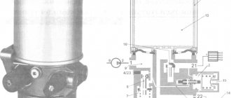
The hydraulic oil filter of the manipulator becomes clogged and can no longer perform its function.
The hydraulic filter for the manipulator can be quite expensive. Therefore, when servicing CMUs, they are often not replaced with new ones, but rather they are tried to be revived or extended their service life in order to reduce operating costs.
The service life of a hydraulic filter on a CMU depends on several factors. Firstly, it is dirt holding capacity, i.e. the ability to hold a certain volume of solid contaminants. Secondly, this is strength - it determines how long the CMU filter can operate without mechanical damage.
When increasing the service life of the oil filter on the manipulator, you can only act on the dirt holding capacity. There are also methods for regenerating a hydraulic filter that involve washing the membrane instead of replacing it.
Increasing the dirt holding capacity of the hydraulic filter on the manipulator
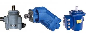
There are many types of hydraulic filters for CMU.
To change the dirt holding capacity of the CMU oil filter, you can use one of the following methods:
- change the filter material;
- change the filter configuration;
- change filter volume.
Any changes to the configuration of the hydraulic filter on the CMU will increase its price. But this is usually justified by the increased service life of the filter element. For example, if you double the working area of the hydraulic filter of the manipulator, then the dirt holding capacity will increase three times. Thus, while maintaining the intensity of use, the oil filter will last three times longer.
In practice, the easiest way to extend the life of the manipulator filter is to place a larger filter element in the housing. But, of course, this method is not suitable for all modifications of the hydraulic filter: in some models there is simply no free space to replace it with a larger cartridge. In this case, you can install a second manipulator hydraulic filter.
Connecting the second CMU oil filter in parallel
As a result of such actions, you can get a double benefit in the oil filter area. An additional bonus is that the speed of the oncoming flow will decrease, i.e. the hydraulic oil pressure on the surface of the filter element will decrease. This is important, since it is the excess pressure of the working fluid that often leads to mechanical damage to the hydraulic filter on the CMU.
By connecting a second manipulator hydraulic filter in parallel, you can increase the dirt holding capacity of the technical fluid cleaning system. As a result, the filter replacement interval in the CMU will increase. At the same time, the cost of purchasing the hydraulic filter itself will not change (since two will need to be changed at once). But the gain in maintenance frequency is noticeable.
Not all manipulator hydraulic filters can be connected in parallel
Connecting the second hydraulic filter KMU in series
Not all models of manipulators can mount an additional hydraulic filter in parallel. If it is not possible to install additional pipelines of the circulation circuit, then installation is carried out sequentially. As a result:
- the filtration area doubles;
- oil pressure decreases;
- the speed of the oncoming flow decreases.
The serial connection of the second CMU hydraulic filter also allows you to increase the replacement interval, but does not in any way affect the number of oil filters to be replaced.
Despite all the ways to extend the service life of the hydraulic filter of the manipulator, the main thing remains compliance with the operating rules of the CMU.
Regeneration of the hydraulic filter KMU
Instead of replacing the filter in the CMU, you can perform its regeneration, i.e. recovery. During this procedure, contaminants are removed from the filter elements, resulting in increased throughput. True, it is unlikely that it will be possible to restore the oil filter of the manipulator to factory parameters: with each subsequent cleaning, the performance characteristics of the hydraulic filter will deteriorate, and the replacement interval will decrease.
It is not recommended to perform more than ten restoration cycles for one CMU oil filter.
Methods for cleaning the manipulator hydraulic filter
The most effective ways to clean the hydraulic oil filter on a CMU are the following:
- Ultrasonic bath.
This technique gives excellent results when removing blockages from the steel mesh of surface filters.
- Electrostatic separation.
To clean the filter, a special separator is connected to the hydraulics of the manipulator. It circulates hydraulic oil through a system of pipelines placed between the electrodes. Under the influence of the electromagnetic field created by the electrodes, mechanical inclusions are pulled out of the hydraulic oil, as well as decomposition products formed when the technical fluid is heated above 60 degrees. In essence, electrostatic separation is a replacement for the filter in the CMU. If in a particular case the cost of electrostatic cleaning turns out to be comparable to the cost of the manipulator oil filter, then this method will be effective in increasing the replacement interval of filter elements.
Previously, we wrote about what technical characteristics of a truck crane exist.
Providing truck crane services: when is it profitable to rent equipment, how to conclude an agreement
What types of burners are there: by fuel type, gas, by application, for boilers
Screw screw conveyors for bulk materials: device, characteristics, types of spiral conveyors
Metal cable trays: advantages, types, which ones to choose
Truck tire rating: for drive and steering axles, for semi-trailer with characteristics in the table
Renting a front loader with or without a driver: which is more profitable?
Which trailer is better - single-axle or two-axle: which one is more convenient, which one is better to choose for a car or truck
Caterpillars for special equipment: what advantages do they have over wheeled vehicles?
How to choose tires for special equipment: choose the right one
Diagnostics of Common Rail diesel injectors: types, faults, repairs
Productivity of jaw crushers: what it depends on, calculation formula
Purpose
The Amkodor TO-18 B front loader was developed for loading and unloading operations. In practice, the machine is used not only for its intended purpose, but also for transporting goods over short distances. The equipment can be used in construction, public utilities and agriculture.
A variety of applications is provided by numerous interchangeable working equipment for the TO-18. The loader is adapted for work in open-pit mining of rocks and other deposits of bulk materials.