Westinghouse air brake is the name given to brake actuator systems that use compressed air to operate.
The first reliable (automatic) air brake system was patented by George Westinghouse on March 5, 1872. Westinghouse's invention was truly revolutionary for railroads, providing reliable braking, which, in turn, expanded the range of speeds at which trains of those years could travel. Westinghouse also proposed many additions to his invention, making it possible to use it in a wide variety of automatic braking systems.
In the simplest air brake system, called a direct-acting system (or direct-acting brake), compressed air presses against a piston in a cylinder. The piston is connected to the brake pad, which rubs against the wheel, causing it to stop.
The air brake system is used on trucks, buses, on domestically produced vehicles such as ZIL, Ural, KAMAZ, KrAZ, on foreign-made vehicles, this brake system is more suitable for trucks because it is more reliable than other braking systems.
The goals and objectives of writing the work: to provide an explanation of the ZIL-130 brake system, the design and repair of the ZIL-130 brake system and its maintenance, as well as to explain the technological process of disassembling and assembling the parking brake of a ZIL-130 car.
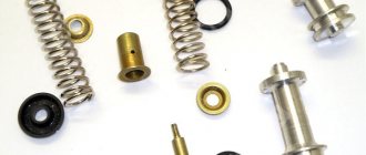
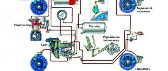
Compressed air is used as an energy source for braking. The pneumatic brake drive allows the development of large braking forces with little driver effort required only to open the device that allows compressed air into the system. This drive is used on the ZIL-130 car; the pneumatic brake drive system of the ZIL-130 car includes a compressor, air cylinders, pressure gauge, brake valve, wheel brake chambers, brake pedal, pressure regulator, safety valve, air bleed valve, water condensate drain valve and oils, isolation valve and connection head.
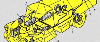
Diagram of the pneumatic drive of the brakes of the ZIL-130 car (Figure-1): 1 and 4 - brake drums; 2, 5, 10 and 13 – brake chambers; 3 - compressor; 6 — air cylinder; 7–safety valve; 8 — air bleed valve; 9 — tap for draining condensate water and oil; 11–disconnect valve; 12 — connecting head; 14 — two-section brake valve; 15–service brake lever; 16 – pressure gauge; 17–pressure regulator; 18– air exhaust pipe to the windshield wiper; 19 — brake pedal.
The compressor supplies the system with compressed air. The air entering the compressor through the air cleaner is compressed in it and then enters the cylinders. It is impossible for air to escape from the cylinders due to the presence of a check valve in the compressor.
The air pressure in the pneumatic brake drive system is monitored using a pressure gauge. When you press the pedal with your foot, access through the brake valve opens for compressed air from the cylinders into the brake chambers of the front and rear wheels, which activates the mechanisms that move the brake pads apart. The release of the brakes occurs thanks to the tension springs of the pads.
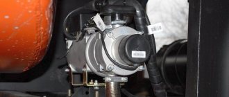
The two-cylinder compressor of the ZIL-130 car is installed on the right side of the engine block head. The main parts of the compressor are as follows: cylinder block, cylinder head, crankcase, front, rear and bottom covers.
The compressor crankshaft, rotating in ball bearings, is connected to the pistons by connecting rods and piston pins. At the front end of the crankshaft there is an oil seal and a pulley on the key, which is secured with a nut.
The compressor pulley is driven by a V-belt from a pulley mounted on the fan shaft. At the rear end of the crankshaft there is a seal and a nut for tightening the ball bearing.
A hole is made in the wall of the cylinder block for air entering the cylinders through the intake plate valves.
A plug is screwed into the block head above each cylinder, into which the spring of the discharge valve is placed, seated in the seat. The lower connecting rod heads are detachable and have shims.
Compressor lubrication system is combined. Oil from the engine lubrication system (from the main line) is supplied through a tube into the compressor crankshaft.
The connecting rod bearings, filled with antifriction alloy, are forcibly lubricated, and the remaining parts are lubricated with spray oil. From the compressor crankcase, waste oil is discharged through a special tube into the engine crankcase.
The compressor has a liquid cooling system connected to the engine cooling system. When one of the pistons moves down, a vacuum is created in the compressor cylinder and air is sucked into it through the engine air cleaner and the reed inlet valve.
As the piston rises, the air is compressed and through the valve enters the pipeline leading to the air cylinders and then into the pneumatic system, then this process is repeated.
Brake system ZIL-130
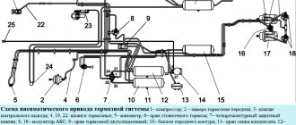
The brake system of ZIL 130-431410 vehicles can be multi-wire or single-circuit, depending on the time of production of the vehicle. Brake system diagrams are shown in Figures 12-15 and 12-16. The multi-circuit brake drive of ZIL-431410 vehicles differs from ZIL-433360 vehicles in the number of devices used and their connection. The brake drive devices themselves are the same. By car
multi-circuit braking system
Diagram of a service brake system with a single-circuit undivided drive
single-circuit braking system
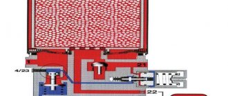
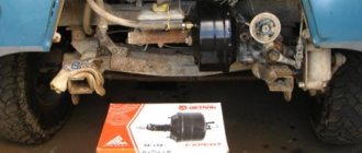
Braking systems, as we see in the pictures, come in 2 types. We will make a multi-circuit system similar to a single-circuit one. Let's remove unnecessary taps, which we can say are not needed for the operation of the brake system. Let's look at the third picture. Here I want to show how I made a single-circuit system from a multi-circuit ZIL-431410 system.
I removed valves such as: a brake force regulator, a trailer brake system control valve with a two-wire drive, a single safety valve, pneumatic-electric pressure reduction sensors, connecting heads for trailer brake drives. As they say, the simpler, the more reliable. The fewer air pressure tubes, the less air will bleed.
rebuilt brake system
In the upper and lower pictures, look at how the diagram of the pneumatic brake drive is made and you will see the difference. Using this diagram, you will make all the connections, I think you will figure it out, there is nothing complicated.
Maintenance and repair
Maintenance and repair of the ZIL-131 should only be carried out with the engine turned off and at a special site.
Reasons why repair work is required:
- The engine gets very hot and the muffler fires.
- Resource exhaustion, which causes the crankshaft, cylinder block, transmission and other main components of the car to fail.
- Burnout of the piston device.
- The presence of damage and cracks on the engine housing, gearbox and cylinder block.
- Short circuit or open circuit.
Maintenance involves replacing the oil fluid, external inspection of units and replacing consumables.
Why it won't start and what to do
The power unit may not start due to a lack of fuel in the system, a stuck air throttle valve, or clogged jets.
In order to repair the engine, you must:
- Blow out the fuel lines.
- Check the functionality of the needle valve located on the carburetor.
- Inspect the fuel pump for defects and damage.
- Blow out cylindrical elements.
- Crank the engine using an electric starter with the throttle valves fully open.
- Check the operation of the air damper.
- Wash the jets with acetone and blow through with air.
See » TOP 2 modifications of trucks based on the ZIL-MMZ-4502 dump truck
Carburetor adjustment
With a properly adjusted carburetor, the throttles and choke valves will open and close in response to the position of the brake pedal.
Carburetor adjustment takes place in several stages. First, the manual and foot drive of the throttles are adjusted, only after that they move on to setting the air damper.
The foot-type drive is adjusted using a threaded fork, and the manual drive is adjusted using a clamp that is installed on the end of the drive cable.
At low engine idle speeds, vacuum from the intake manifold is transmitted through the opening of the idle system, after which the working fluid enters the lubrication system.
How to set the ignition
In order to set the ignition on a ZIL, you must perform the following steps:
- Set the piston mechanism of cylinder number 1 to the top dead center position.
- Rotate the crankshaft until the hole on the crankshaft pulley aligns with the top dead center mark.
- Position the groove on the distributor drive shaft.
- Insert the drive into the slot of the block.
- Rotate the crankshaft to the installation angle.
- Remove the mounting bolt from the plate.
- Turn on the ignition.
- Rotate the switchgear housing into the drive socket.
- Check that the wires on all cylinders are installed correctly.
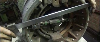
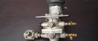
Parking brake system
Provides vehicle stability on a horizontal road or slope. The drive of the brake mechanisms of the parking brake system is mechanical, from brake chambers with spring energy accumulators. Installed on the rear axle. When the vehicle moves, the power springs of the energy accumulators are compressed by air pressure.
When the air pressure in the cylinders of the energy accumulators drops, the springs activate the brake mechanisms of the rear wheels. The parking brake system is controlled by a manual brake valve located in the cab to the right of the driver's seat.
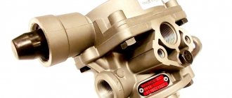
brake valve
brake system zil-130
The condition of the brake systems is monitored using a light and sound alarm system, the sensors of which are installed at various points of the pneumatic brake drive, as well as control outlet valves.
1-compressor; 2-pressure gauge; 3-receiver (compressed air tanks); 4-rear brake chambers; 5.6- tap for connecting to a trailer; 7-pneumatic line; 8-main brake valve; 9-front brake chambers.
130-3507015 - catalog number
Name:
Hand brake shoe ZIL
Contents: pcs
In our company you can buy original spare parts: hand brake pad at a wholesale price of 873.1 rubles. Item number: 130-3507015. Or you can choose replacement options using code 130-3507015 with non-original spare parts or analogues from other manufacturers.
We deliver to all regions of Russia using various transport companies.
For example, to Stavropol (Stavropol Territory) or to Vladivostok (Primorsky Territory), as well as to Kazakhstan: for example, to Alma-Ata.
We collect requests for auto parts for PAZ, GAZ, UAZ, ZMZ. We try to complete it 100%. Our store for the wholesale sale of auto parts is located in Nizhny Novgorod - we are waiting for orders and will be glad to see you among our regular customers. You can always send your request for a quote to the email address to evaluate our price level.
Delivery to the transport company terminal in Nizhny Novgorod is free. The cost of delivery to your city can be calculated on the website of the selected transport company. Departure point: Nizhny Novgorod.
We work with wholesale companies, bus depots, auto transport companies, auto parts stores, repair shops and service stations, and wholesale clients.
Regular customers are provided with discounts and deferred payment.
content .. 120 121 122 123 124 125 126 127 128 129 ..BRAKE SYSTEMS OF THE MODERNIZED ZIL-130
Control valve for the brake system of a trailer with a two-wire drive of the modernized ZIL-130
(Fig. 104) is designed to supply air to the control line of the trailer brake system, as well as to turn on the control valve for the single-line trailer brake system.
Terminal I of the valve is connected to the brake valve section that controls the brake mechanisms of the front axle wheels, terminal II is connected to the manual brake valve, terminal III is connected to the brake valve section that controls the brake mechanisms of the rear axle wheels, terminal IV is to the trailer control line and the single-wire control valve. trailer brake system, output V - through a single safety valve with air cylinders. Air is released into the atmosphere through terminal VI.
When the car is moving, compressed air is constantly supplied to terminals II and V and acts from above on the membrane 1 and from below on the middle piston 17, holding the piston 20 in the lower position. In this case, terminal VI, i.e., the trailer control line, is connected to the atmospheric terminal VI through the open central hole in the valve body 15 and the lower piston 20.
When compressed air is supplied to terminal III from the brake valve section, the upper pistons 7 and 8 simultaneously move down. Small
The upper piston 8 sits with its seat on valve 15, blocking the atmospheric outlet in the lower piston and lifting valve 15 from the middle piston 17. Compressed air from outlet V, connected to the air cylinders, flows to outlet IV and then into the control line of the trailer until until the pressure in the cavity under the pistons 7 and 8 becomes equal to the pressure of the compressed air supplied to terminal III. After this, valve 15, under the action of spring 16, blocks the access of compressed air from terminal V to terminal IV. In this way, the control valve follows the action.
After the supply of compressed air to port III from the brake valve section is stopped, when the brake is released, compressed air from port III escapes into the atmosphere through the brake valve. The large upper piston 7, under the action of the conical spring 13 and the compressed air in port IV, moves upward along with the small upper piston 8. The seat of the small upper piston comes off the valve 15, connecting pin IV to atmospheric port VI through the hollow lower piston 20.
When compressed air is supplied to terminal I from another section of the brake valve, it enters under the membrane 1 and moves the lower piston 20 together with the middle piston 17 and valve 15 upward. The valve reaches the seat in the small upper piston 8, closes the atmospheric outlet and comes off the seat of the middle piston 17. Air enters
from terminal V, connected to the air cylinders, to terminal IV and further into the control line of the trailer until its effect on the middle piston 17 from above is balanced by the pressure on the membrane from below. After this, valve 15 blocks the access of compressed air from terminal V to terminal IV. Thus, a tracking action is carried out.
When compressed air is released from outlet I into the atmosphere through the brake valve, the pressure under the membrane 1 decreases, and the lower piston 20, together with the middle piston 17, moves down. Valve 15 lifts off the seat in the upper piston 8, communicating port IV with atmospheric port VI through the hollow lower piston.
With the simultaneous supply of compressed air to terminals III and I, the large 7 and small 8 upper pistons simultaneously move down, and the lower piston 20 with the middle piston 17 moves upward. Filling the trailer control line through terminal IV and releasing the brakes occurs in the same way as described above.
When the parking brake system is turned on, the pressure in port II and above membrane 1 decreases. Under the action of compressed air from port V, the middle piston 17 together with the lower piston 20 moves upward. Filling of the trailer control line through terminal IV and braking occur in the same way as when compressed air is supplied to terminal I. The tracking action is carried out in this case by the interaction of compressed air pressure on the middle piston 17 from below and membrane I from above.
When air is supplied to terminal III or when air is supplied simultaneously to terminals III and I, the pressure in terminal IV, connected to the trailer control line, exceeds the pressure in terminal III, which ensures the leading action of the trailer braking system. The advance pressure is adjusted using screw 10.
Rice. 104. Control valve for the trailer brake system with a two-wire drive: 1 - membrane; 2 - middle body; 3, 4, 6, 12, 18 and 23 - sealing rings; 5 — upper body; 7 - large upper piston 8 - small upper piston; 9 — spring plate; 10 — adjusting screw; 11 and 16 — springs; 13 - conical spring; 14 and 19 — support rings; 15 - valve; 17 - middle piston; 20 - lower piston; 21 — lower body; 22 — atmospheric outlet housing; 24 - nut; 25 — washer
content .. 120 121 122 123 124 125 126 127 128 129 ..