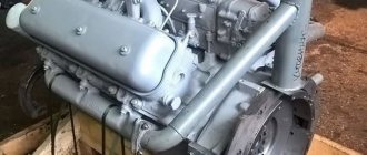
Installing cylinder heads, valve rocker arms and adjusting valve clearances
The cylinder head mounting studs are screwed into the right and left rows of the cylinder block, having previously lubricated the threaded holes for the studs in the block with diesel oil.
The studs are screwed in over the entire length of the thread with a torque of 80-100 Nm (8-10 kgcm); they should protrude above the plane of the block by 122 mm, which is checked with a bushing (Fig. 1).
Before installing the cylinder head, it is necessary to wipe the mating surface.
We install the cylinder head gasket on the studs so that it fits onto the pins, and the gasket surround onto the cylinder liner collars.
The cylinder head assembly must fit freely onto the studs and dowel pins without impact.
Then we screw the cylinder head nuts onto the studs and tighten them.
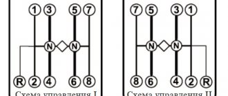
The nuts must be tightened in ascending order of numbers (see Fig. 2).
After the first tightening with a torque wrench, it is necessary to re-check the required torque of 220-250 Nm (22-25 kgcm) on each nut, following the indicated sequence.
The pusher rods are installed in the windows of the cylinder block and at the same time the tip of the rod is aligned with the heel of the pusher.
First, wipe the rod and lubricate the tip with diesel oil.
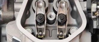
The right and left valve rocker arms with the axle assembly are installed so that the axle locating pins fit into the holes in the cylinder head, and the sphere of the adjusting screw is aligned with the tip of the rod.
The adjusting screw must be screwed into the rocker until it stops.
Then screw the rocker arm axis mounting bolts into the cylinder heads and tighten them to a torque of 120-150 Nm (12-15 kgcm).
Valve clearances are adjusted simultaneously on two cylinders and a dial is used (Fig. 4).
The dial is installed on the crankshaft pulley, and pin 3 is inserted into the threaded hole on the timing gear cover.
Thermal clearances of the YaMZ-326 engine are adjusted in the following sequence:
- rotate the crankshaft clockwise with a wrench using the pulley bolt, observe the movement of the intake valve of the first cylinder and set the moment when it is completely closed.
After this, the shaft is turned in the same direction until the marks on the crankshaft pulley align with the mark 1-4 YAM3-236 on the dial;
- adjust the gaps between the toes of the rocker arms and the ends of the valves of the first and fourth cylinders.
After tightening the locknut of the adjusting screw, the 0.25 mm thick feeler gauge should fit freely into the 0.30 mm thick gaps - with force.
After turning the crankshaft, it is allowed to change the gap within 0.20 - 0.35 mm;
— combining on the compression stroke the order of operation of the cylinders (1 – 4 – 2 – 5 – 3 – 6) with the mark on the pulley with marks 1 – 4, 2 – 5, 3 – 6 YaMZ – 236 on the dial, adjust the clearances for the remaining cylinders.
When adjusting the thermal clearances of the YaMZ-238 engine, the same techniques and methods are used as for the YaMZ-236 engine:
— on the compression stroke, combine figure 3 on the pulley with mark 1 – 5 YaMZ – 238 on the limb;
— adjust the valve clearances of the first and fifth cylinders;
combining on the compression stroke in the order of operation of the cylinders (1-5-4-2-6-3-7-8) the mark on the pulley with marks 4-2, 6-3 and 7-8 YaMZ-238 on the dial, adjust the valves of the rest cylinders
The control valve pushrods must rotate freely by hand.
The gap is adjusted using an adjusting screw; After adjustment, you need to securely fasten the screw with a nut and check the gap.
Installation of injectors, fuel lines and connecting pipe.
A set of injectors of the same spray group is installed on the engine.
The spray group is applied to the surface of the injector body.
Before installing the nozzles, wipe the inner surface of the glasses, and put one sealing copper washer on the sprayer.
The injectors are installed so that the fitting seal fits into the recess of the cylinder head.
The injector mounting brackets are installed on the cylinder head studs, washers are put on and nuts are screwed in, which are tightened with a torque of 50-60 Nm (5-6 kgf m).
Drainage tubes are installed on the left and right cylinder heads, having previously removed the transport plugs from the injectors.
Drainage tubes are attached to the nozzles with connecting nuts and bolts, having previously placed washers under the tips of the tubes and under the heads of the bolts.
To ensure a reliable seal in all cases, it is necessary to orient the washers with the tops of the cones away from the tips of the tubes outward.
Fuel return lines are installed in the camber between the cylinders and bolted to the right and left cylinder heads.
To ensure a more rigid fastening, a clamp is installed on each fuel line and secured to the flange stud of the left intake pipe.
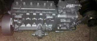
High-pressure fuel lines are attached to the fittings of the high-pressure fuel pump and injectors in a certain sequence corresponding to the operating order of the high-pressure fuel pump sections.
The YaMZ-236 engine pump has an operating order that corresponds to the operating order of the engine cylinders (1 – 4 – 2 – 5-3-6).
The order of operation of the pump sections of the YaMZ-238 engine differs from the order of operation of the cylinders of this engine.
If the operating order of the engine cylinders is 1-5-4-2-6-3-7-8, then the pump sections operate in the sequence 1-3-6-2-4-5-7-8.
Connection diagrams of pump sections with cylinders of YaMZ-236 and YaMZ-238 engines are shown in Fig. 5.
The connecting pipe of the intake pipelines is installed so that the flange under the compressor air duct is directed towards the front of the cylinder block.
The pipe is attached to the flanges of the inlet pipelines, having previously placed gaskets with assembled mesh and rubber gaskets on the flanges and secured with bolts and washers.
The oil dipstick is installed in the guide tube, after wiping it.
Then install the cylinder head covers, which are secured with screws on one or two threads, and remove the engine from the stand.
Install plugs on the technological holes and secure with bolts.
Cardboard spacers must be installed under the plugs.
Running-in and testing of engines after repair is carried out on STE-160-1500 stands with electric brakes.
At these stands you can test YaMZ-236 and YaMZ-238 engines of all modifications.
The characteristics of electric brakes for test benches are given in the table.
| Characteristics of electric brakes | ||
| Index | Electric brake | |
| AKB-104-4 | AK-102-4 | |
| power, kWt | 160 | 160 |
| Synchronous rotation speed, min-1 | 1500 | 1500 |
| Torque, Nm (kgcm) | 1070 (107) | 1100 (110) |
| Limit speed of engine crankshaft when operating in generator mode with rated torque, min-1 | 3000 | 2500 |
The engine running-in and testing stand must have the equipment necessary to measure engine power, crankshaft speed, hourly fuel consumption, temperature of water leaving the engine (from the right and left water pipes), oil temperature in the engine sump, oil pressure in the line , fuel injection advance angle in degrees of crankshaft rotation angle.
Fuel consumption must be measured on scales with a measurement limit of up to 15 kg, time is counted using a stopwatch with a division value of 0.1 s; measurement of rotation speed - with a manual tachometer or tachoscope with a division value of no more than 10 minutes.
The capacity of the supply tank should be 10 - 12 l, the level of the bottom of the measuring tank should be at least 500 mm from the axis of the inlet of the fuel pump, the internal diameter of the inlet and outlet fuel lines should be at least 8 mm.
Fuel lines should not touch the measuring tank and should be immersed in fuel to a depth of no more than ⅓ of the height of the tank from its bottom.
A reflector is installed at the submerged end of the fuel line that takes fuel away from the engine, preventing the direct direction of the fuel stream to the bottom of the tank and helping to equalize the temperature of the fuel in the tank.
The engine installed on the stand must be fully equipped (with the exception of the fan impeller, generator, compressor).
Engine running-in and testing is carried out using L grade diesel fuel.
During the running-in period, diesel oil is poured into the engine sump, fuel injection pump housing and regulator housing up to the upper marks of the oil level indicators.
The air filters are filled with diesel oil in the amount of 1.6 liters for the YaMZ-236 engine and 1.4 liters for the YaMZ-238 engine.
The oil temperature is maintained using technological oil radiators (at the beginning of the run-in not lower than 50˚ C).
Running-in and testing of the engine is carried out in special modes and includes cold and hot running-in, control acceptance.
Cold running-in of the engine
Before starting the stand, the crankshaft must be turned manually several times to ensure that the engine is in good condition and that it is installed correctly on the stand, and to check and, if necessary, adjust the thermal clearances in the valve mechanism.
During the break-in process, the oil pressure in the system, the oil supply to the rocker arm bearings and the tightness of the injector seals in the cylinder heads are checked.
A stethoscope can be used to listen for noises and knocks of timing gears, connecting rod and main bearings, piston pins and pistons.
If defects are detected, running-in should be stopped and continued after elimination.
The cold running mode is shown in the table.
At the end of the cold break-in, it is recommended to change the oil in the engine sump and wash the oil filters.
To wash the centrifugal filter rotor, unscrew nut 3 (see Fig. 6) of the filter cap, remove cap 1 and the rotor assembly.
The rotor is disassembled, sediment is removed from the cap 10 and rotor 11, and washed with diesel fuel.
The filter is assembled in the reverse order, checking the condition of the gasket 15, the cleanliness of the nozzle holes 22, the condition of the washer 2 and the position of the mesh 8.
To wash the filter for rough cleaning of the oil, you need to drain the oil from the Filter Housing through the hole closed with plug 2 (see Fig. 7), unscrew the bolt 11 securing the Filter cap, remove the cap 7, the top cover 8 and the filter element 5.
The filter element removed from the engine is placed in a bath with a solvent (gasoline or carbon tetrachloride) for 3 hours.
After 3 hours, the element is washed with a soft hair brush, rinsed in pure gasoline or carbon tetrachloride and blown with compressed air.
During washing, technological replaceable filter elements are installed.
| Engine cold running mode | ||
| Crankshaft rotation speed, min-1 | Duration of engine running-in, min | |
| YaMZ-236, YaMZ-238, YaMZ-2Z8A, YaMZ-238G, YaMZ-238K | YaMZ-238I | |
| 600 | 10 | 10 |
| 800 | 10 | 15 |
| 1000 | 5 | 15 |
| 1500 | 5 | — |
| Total | 40 | 40 |
Cars on which YaMZ-236 and YaMZ-238 were installed [edit | edit code]
- MAZ-500 (1965—1990). YaMZ-236 (180 hp).
- MAZ-503 (1965—1977). YaMZ-236 (180 hp).
- MAZ-504 (1965—1982). YaMZ-236 (180 hp).
- MAZ-509 (1966-1990). YaMZ-236 (180 hp).
- MAZ-516 (1973-1980). YaMZ-236 (180 hp).
- MAZ-5335 (1977-1990). YaMZ-236 (180, 300 hp).
- MAZ-5549 (1977-1990). YaMZ-236 (180 hp).
- MAZ-5551 (since 1985). YaMZ-236 (180 hp).
- MAZ-5432 (since 1981). YaMZ-238 (240, 250, 280, 300, 330, 360, 425 hp), YaMZ-236 (180 hp).
- MAZ-5516 (since 1995). YaMZ-238 (400 hp).
- MAZ-6422 (since 1978). YaMZ-238 (320, 330, 360, 425 hp).
- Ural-4320 (since 1993). YaMZ-236 (230 hp), YaMZ-238 (300 hp).
- KrAZ-255 (1967—1994). YaMZ-238 (240 hp).
- KrAZ-6443 (since 1992). YaMZ-238 (330 hp).
- KrAZ-6322 (since 1994). YaMZ-238 (330 hp).
- Ural-5323 (since 1989). YaMZ-238 (300 hp).
- KamAZ-5320 (1976—2000).
- LiAZ-5256.30 (2001-2004). YaMZ-236NE2 (230 hp).
- MAZ-104.X25 (2004-2005). YaMZ-236NE2 (230 hp).
Hot engine run-in
Before starting the engine, it is necessary to adjust the fuel injection advance angle.
To do this, check the relative position of the marks on the fuel injection advance clutch and the drive half coupling of the fuel pump drive shaft (the marks should be on one side);
— remove the high pressure pipe of the first section of the injection pump;
— a momentoscope is installed on the fitting of the first section of the pump.
After making sure that the regulator bracket is in the fuel supply on position, pump fuel into the engine power supply system with a manual booster pump for 2-3 minutes and rotate the engine crankshaft clockwise (as viewed from the fan) until fuel appears in the glass tube.
You can rotate the crankshaft using the crankshaft pulley mounting bolt or using a crowbar using the holes in the flywheel with the flywheel housing hatch cover removed.
Next, pour excess fuel out of the glass tube, shake it with your finger, turn the crankshaft counterclockwise about 118 turns and, slowly turning the crankshaft clockwise, carefully monitor the fuel level in the glass tube.
At the moment the fuel level begins to move in the tube, stop the rotation of the shaft and check the relative position of the marks:
— the mark on the crankshaft pulley should be opposite the mark with the number 20 on the cover 1 of the timing gears (Fig. 8, a) or the mark with the number 20 on the flywheel 4 should coincide with the pointer 3 on the flywheel housing (Fig. 8, b).
For the YaMZ-238K engine, the adjustment marks are combined with mark 14.
If, at the moment the fuel begins to move in the tube, the marks have not yet aligned, it is necessary to loosen the bolts, rotate the drive shaft coupling on its flange against the direction of its rotation, tighten the fastening bolts and check the injection timing again.
The discrepancy between the marks should be no more than one division.
If, at the moment the fuel begins to move, the risk tube has already passed the aligned position, the drive roller coupling must be turned in the direction of its rotation.
The displacement of the drive shaft coupling relative to its flange by one division corresponds to four divisions on the flywheel or timing gear cover.
After starting the engine, check the tightness of all connections in the engine fuel system.
The temperature of the water leaving the engine should be 75 – 95˚ C, while the difference in temperature of the water leaving the right and left pipes should not exceed 5˚ C.
It is recommended to maintain the temperature within the specified limits using a process radiator.
The oil pressure in the line at a temperature of 80 - 90˚ C should be 0.5 - 0.7 MPa (5 - 7 kgf/cm2) at the rated crankshaft speed and at least 0.1 MPa (1 kgf/cm2) at rotation 500 min-1.
Ejection and leakage of oil, water and fuel, as well as gas breakthrough at joints are not allowed.
Signs of defects are not sweating, the formation of oil stains and individual drops in the places of the stuffing box seals, with no more than one drop falling within 5 minutes, under any engine operating mode;
— slight sweating without drop formation at the connectors and connections;
— release of oil and condensate through the outlet pipe of the crankcase ventilation system in an amount of no more than two drops per minute at the nominal crankshaft speed;
— release of fuel through the drain tube of the injectors in the form of drops, as well as a mixture of fuel and oil from the drain tube of the injection pump housing;
— the release of water and lubricant from the drainage hole of the water pump is no more than one drop per 3 minutes, as well as drops of water when the engine is stopped;
- slight sweating without oil dripping through micropores on the annular rib of the cylinder head.
During the running-in period, individual drops of the fuel-oil mixture may be released from the exhaust pipe.
Hot running-in of engines is carried out in the modes given in the table
Replacing the MAZ cylinder head gasket
DIY cylinder head tightening torque for Lada Priora 8 and 16 valves
Don't risk your engine - if you don't replace the product in time, other parts may break.
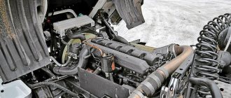
Below you will see a short report on the work done by one of the owners of the Belarusian MAZ car.
So, as described above, the failure of the cylinder head gasket of the internal combustion engine at MAZ was indicated by an antifreeze leak.
- drained the liquid;
- dismantled the valve cover and pipelines;
- they removed the return line.
To replace the MAZ cylinder head gasket, we unscrewed the nuts that secure the rocker arm axles. Only after this we moved on to dismantling the rocker arms themselves and the rod.
We worked with the Euro 3 cylinder head gasket for a short time.
However, replacement required compliance with one rule - when you unscrew the head, remember the direction. Use the same direction when tightening.
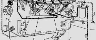
The photo below shows the process of removing the head.
After purchasing a cylinder head gasket 260 or 240, we begin assembly in the reverse order.
For convenience, we attach a diagram showing the sequence of tightening the head.
After proper assembly and replacement, the cylinder head gasket of the internal combustion engine on a MAZ should not overheat and wear out quickly.
But we recommend that you carry a spare one, just in case.
If you don’t know how to choose and buy the right MAZ cylinder head gasket, call us, we’ll help you out.
In our catalog you will find only high-quality parts at reasonable prices.
And finally, an interesting video on grinding the cylinder head.
It’s impossible to repeat in a garage environment :)
Control of the size of gaps of thermal compensators
According to the manufacturer's recommendations, adjustment should be made with an increased size of 0.25 mm. The most accurate measurement of clearances can be made at the moment of the compression stroke. To do this, turn the crankshaft. The intake valve on the first cylinder should close. The end that works in conjunction with the rocker arm will take the top point. After this, you need to rotate the crankshaft 120 degrees. This will allow you to accurately measure two valves at once.
Determining the cylinder number
You need to stand in front of the engine from the front of the car. The first cylinder is on the left. On the opposite side is the fifth cylinder. The crankshaft can be turned using a special wrench or a spanner. The gap size is determined using a feeler gauge. It should fit between the top of the valve and the bottom of the rocker without any problems. If a probe with a measuring sheet thickness of 0.25 mm fits freely, but with a size of 0.30 mm it is not possible to push the measuring sheet through, then it will not be possible to set the required gap.
Before adjustment, the rocker arms must be pressed.
- In cylinders one through four, the exhaust valves must be pressed against the end of the axle.
- The intake valves must be pressed against the thrust washer.
- In the fifth, sixth, seventh and eighth cylinders, the parts are pressed in the opposite way.
The process of adjusting valves on MAZ YaMZ 238
If the gap size does not correspond to the standard, the following actions must be taken.
- First, unscrew the nut on the adjusting screw. It is located on the rocker arm. After this, a probe of a given size is inserted between the closing valve and the rocker arm.
- Next, you need to turn the screw with a screwdriver until the required gap is created. To avoid further turning of the screw, carefully tighten the nut.
- If, when checking the size of the gap, a discrepancy between the size and the norm is discovered, then it is necessary to carry out the steps described above. Valve adjustment has its own order, which must not be violated. The setting is carried out from the fifth cylinder. Next, fourth, second, sixth, third, seventh, eighth. In this case, the cylinder inlet must be closed.
- At the end, the clearances on each cylinder are re-checked. Due to the possible presence of inaccuracies in the dimensions of parts at MAZ, a deviation from the norm of no more than 0.35 mm is allowed.
After adjusting the valves on the YaMZ-238, it is recommended to start the power unit. The absence of extraneous sounds, vibrations and noise indicates the correct setting
It is also important to pay attention to the condition of the cylinder head gasket. If it is in unsatisfactory condition, it needs to be replaced. The final operation will be to install the block head cover in place
If, after a short period of time, extraneous noise appears in the operation of the YaMZ V-shaped engine, it is necessary to adjust the system again. It must be carried out in the exact sequence of activities described above
The final operation will be to install the block head cover in place. If, after a short period of time, extraneous noise appears in the operation of the YaMZ V-shaped engine, it is necessary to adjust the system again. It must be carried out in the exact sequence of events described above.
Work on setting the timing belt is a responsible undertaking, on which the serviceability and reliability of the engine depends. The setup should be carried out by a specialist with practical skills and abilities. Incorrect settings can lead not only to loss of engine power, but also to failure of power unit elements.
How to tighten main bearings and connecting rod bearings
So, taking into account the above, it becomes clear that the tightening torque of the main and connecting rod bearings is extremely important. Now let's move on to the assembly process itself.
- First of all, molar liners are installed in the bed of the molar necks. Please note that the middle liner is different from the others. Before installing the bearings, the preservative lubricant is removed, after which a little motor oil is applied to the surface. After this, the bed covers are placed, after which the tightening is carried out. The tightening torque should be that recommended for the specific model of the power unit. For example, for engines on the VAZ 2108 model, this figure can be from 68 to 84 Nm.
- Next, the connecting rod bearings are installed. During assembly, it is necessary to accurately install the covers in place. The specified covers are marked, that is, their arbitrary installation is not allowed. The tightening torque of the connecting rod bearings is slightly less compared to the main bearings (the indicator ranges from 43 to 53 Nm). For Lada Priora, the main bearings are tightened with a torque of 68.31-84.38, and the connecting rod bearings have a tightening torque of 43.3-53.5.
It should be separately added that the specified tightening torque assumes the use of new parts. If we are talking about an assembly that uses used spare parts, then the presence of wear or other possible defects may lead to a deviation from the recommended standard. In this case, when tightening the bolts, you can start from the upper bar of the recommended torque, which is indicated in the technical manual.