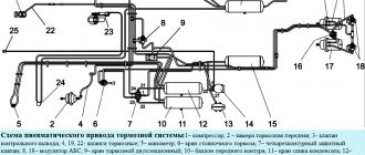
The trailer (semi-trailer) is equipped with service and parking brakes, as well as an electromagnetic valve, which, when the auxiliary brake of the tractor is activated, supplies compressed air to the brake chambers of the trailer (semi-trailer).
The brake mechanisms installed on all wheels of the trailer (semi-trailer) are unified with the brake mechanisms of cars and are common to the service and parking brakes.
The brake mechanisms are activated using brake chambers, the design of which is similar to the design of the brake chambers on the front axle of cars.
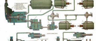
Air distributor KamAZ
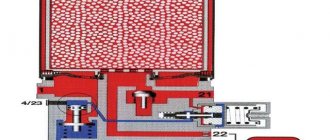
With a single-wire drive, the connecting line is connected to terminal I. The supplied compressed air bends the edges of cuff 1 of piston 2 and passes into the trailer cylinder through terminal IV. The trailer chambers with outlet III are connected to the atmosphere through an open exhaust valve 5, a hollow valve sleeve 6 and atmospheric outlet II.
When the pressure in the line drops (braking), the pressure in terminal I also decreases, and piston 2, overcoming the resistance of spring 9, moves downward under the influence of pressure in terminal IV. Rod 3 and piston 4 move with it. In this case, the outlet valve 5 closes, and the inlet valve 7 opens, and compressed air from the trailer cylinder through terminal IV flows to terminal III and then to the trailer chambers. The tracking action is carried out by piston 4.
If the pressure in the connecting line increases (deceleration occurs), the process occurs in the reverse order. Pistons 2 and 4 move upward, inlet valve 7 closes, then exhaust valve 5 opens, connecting port III (brake chambers) to atmospheric port II.
In the case of a two-wire drive, the supply line is connected to terminal I, and the control (brake) line is connected to terminal V. The compressed air supplied through the supply line through cuff 1 of piston 2 enters the trailer cylinder through terminal IV.
When braking, compressed air supplied to terminal V acts on piston 11 and moves it down. Compressed air from the trailer cylinder enters the brake chambers connected to terminal III. The tracking action is carried out in this case by piston II.
The air distributor has a built-in equalizing valve 10. With a single-line drive, when the air pressure supplied to terminal I does not exceed 5.2 kgf/cm2, valve 10 does not work. In the case of a two-wire drive, when compressed air with a nominal pressure of 7 kgf/cm2 is supplied to terminal I, valve 10 opens and the pressure above and below piston 2 is equalized.
In the event of an emergency drop in pressure in the supply line, valve 10 initially remains open, and the pressure in the trailer cylinder also decreases. If the pressure in the line drops below 5.3 kgf/cm2, then valve 10 closes, and the pressure in the sight cylinder and above piston 2 does not change. With a further decrease in pressure in the line, the air distributor brakes the trailer in the same way as with a single-line drive.
Rice. 127. KamAZ air distributor:
I - output to the connecting or supply line; II - release into the atmosphere; III - output to the brake chambers; IV - output to the air balloon; V - output to the brake control line;
1 - cuff; 2 - piston; 3 - rod; 4 - internal piston; 5 — exhaust valve; 6 — valve sleeve; 7 — inlet valve; 8 - spring; 9 — balancing spring; 10 - equalizing valve; 11 - outer piston.
How does the system function when braking?
When the tractor brakes are activated, compressed air from the double-circuit valve flows to the valve of the single-line valve for controlling the brakes of the MAZ trailer. The mixture fills the plane under the diaphragm. After overcoming the spring force, the diaphragm moves upward along with the pusher, the intake valve closes, and the exhaust element opens. The air escapes into the atmosphere, bypassing a special outlet, a pusher and a hole in the cover.
The stepped piston performs a follower action. If the pressure at the outlet and in the cavity decreases, the force on the piston from below also decreases. In the upper part, this element is subjected to pressure from the corresponding cavity, identical to the force in the second compartment. The hub, in turn, receives force from the first cavity. As a result, due to the pressure difference, the piston moves downward, dragging with it the pusher, which closes the outlet window with its seat. The subsequent increase in pressure causes the complete release of the air mixture from the main brake structure of the semi-trailer. The pusher is in the lowest position, the inlet window is blocked, and the outlet element is open.
Design and principle of operation
The device includes the following elements:
- inlet and outlet type valve;
- spring mechanism and compressor;
- rubber bushing;
- air pressure regulator;
- piston part and diaphragm.
The operating principle of the brake valve of a KamAZ semi-trailer:
- Pressing the brake pedal causes the rod to move to the right, which closes the valve.
- At this time, the valve opens, activating the brake chamber and receiver. The pressure in the brake system will depend on the degree of pressure on the pedal.
- With constant force on the brake pedal, the pressure on the piston increases.
- The force is transmitted through the mechanism of handles and rods to the crane lever, passing through the pusher element and the rubber bushing.
- The movable intake valve seat moves downward along with the piston part.
- The inlet window closes, the exhaust valve window opens.
- Passing through the outlet and the open valve window, the air flow is directed to the valve cavity.
- The pressure in the upper cavity begins to increase. When the pressure level increases, the air flow moves to the area above the piston, activating the operation of the entire mechanism.
How does a brake valve work during braking?
During the active working phase, compressed air is sent to the outlet openings. Through another channel, the compressed gas is sent to the control output, and then to the common line. These manipulations provide such pressure on the piston that it will be balanced with the force from below.
The piston located above operates due to the force of air pressure plus spring force. At the same time, the middle piston must be balanced according to similar factors.
During release, the compressed gas is released into the atmosphere through a corresponding channel. Spring force moves the pistons to the top position. At the same time, the rod moves downwards. Also, the internal and external inputs are connected, because this is facilitated by the separation of the valve from its seat.
The compressed gas forces the rod and piston to move upward, with the small and large piston elements moving in the opposite direction. If the parking or backup brake is activated, the compressed gas is directed through the atmospheric channel of the hand valve and removed from the system. The pressure level behind the membrane decreases, reducing the load on the working parts. At the same time, the seat rests on the valve, separating the interface with the atmosphere. Later, the valve opens, allowing the main line and the outlet flow to communicate with each other.
KAMAZ brake release valve
KAMAZ brake release valve
installed on the air distributor and is designed to release the brakes of the trailer (semi-trailer) in the uncoupled state.
Compressed air from the connecting line of a single-wire drive or the supply line of a two-wire drive is supplied to terminal III and then through terminal II enters the trailer air distributor. Terminal I is connected to the trailer cylinder through an air distributor.
When the trailer is coupled to the tractor and air is supplied to port III, valve stem 1 automatically takes the working position.
While the road train is moving, valve rod 1 is in the working position. The inlet valve is open and compressed air flows from port III to port II.
When uncoupling the trailer, the position of the valve does not change; the trailer is braked due to a drop in pressure in the supply line of the two-wire drive or in the connecting line of the single-wire drive.
If you need to move the uncoupled trailer, you need to pull the valve stem 1 all the way towards you. In this case, inlet port III closes (it is connected to the atmosphere), and the cavities of ports I and II are connected, compressed air from the trailer cylinder, supplied to port I, enters the air distributor through port II, and the trailer is released.
Rice. 128. KamAZ brake release valve:
I—output to the air cylinder; II - output to the air distributor; III - output to the connecting or supply line; 1 - rod.
Work specifics
During braking, the valve compresses the gas to a certain degree until the reaction under the piston equals the force applied to the membrane. The valve in such a situation participates as a controller.
When compressed air passes to the working terminals, the pressure inside the valve cavity exceeds the control values of the output force by 20–100 kPa and the advanced action of the brakes is triggered. The required pressure value can be adjusted by turning the screw.
A single safety valve in the system is used to stabilize pressure in air cavities when a sudden and rapid decrease in pressure in the lines occurs.
A single safety valve in the system is used to stabilize pressure in air cavities when a sudden and rapid decrease in pressure in the lines occurs.
Also, the OZK is entrusted with the mission of preventing gas leakage from the system when the pressure in the vehicle’s main air drive drops. This helps prevent the trailer wheels from inadvertently braking while driving.
The single valve is set to bypass air if the outlet pressure approaches 550 Pa. The compressed gas penetrates through the outlet into the working cavity below the membrane, then its path continues in the cavity in front of the valve, and then the compressed volume of air is sent to the outlet into the main line. The required pressure is adjusted using the adjusting screw.
Isolation valve
This part is involved in the operation of the trailer brake control valve as follows:
- If necessary, it closes the pneumatic line connecting the tractor with the towbar.
- If you install the handle of the device along the axis of the valve, the pusher with the rod will be in the lower position and the valve will be open. Air in a compressed state through it and the corresponding outlet is directed from the car to the semi-trailer.
- When the handle is placed across the frame, the rod and diaphragm move upward under the influence of air pressure and spring. The valve blocks the leads by sitting in the seat. The air mixture flows from the connecting system into the atmosphere, which makes it possible to disconnect the connecting heads.
Below is a schematic representation of the crane, as well as the main symbols and components.
- a — the device is not active;
- b - position of the open tap;
- 1—output to the tractor air cylinder control valve through a single safety valve;
- II - Main outlet of the trailer brake system;
- III - atmospheric output;
- 1 - spring mechanism;
- 2 - valve;
- 3 — diaphragm with rod;
- 4 — return spring;
- 5 - pusher with handle.
Using a Check Valve
A special valve is used in the faucet to control the trailer brakes. It has a small and large piston with springs, as well as three working sections. An inlet valve is installed on the middle piston element, held in the seat through a spring. Additionally, elements such as a membrane, an adjusting screw, a vent hole and a rod are used.
If the system is not in working condition (not braking), then an air flow is constantly sent to the output parts. The gas presses on the diaphragm with the piston to maintain the rod in the down position. These characteristics are facilitated by the increased membrane area. The exhaust valve is removed from its seat, the pistons are moved to their highest position. The inlet element, under the influence of spring force, blocks the passage of air, and in the brake line there is one free outlet to the atmosphere thanks to the rod and relief holes.
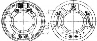
Trailer and semi-trailer parking brakes
The parking brake of a
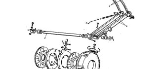
KamAZ is designed to slow it down when coupling, uncoupling and when parking. The parking brake drive consists of a lever 1 with a handle, a cable 4 and two drive levers 5 that act on the brake mechanisms of the rear wheels. To brake the trailer, pull lever 1 all the way. Rice.
130. Trailer parking piston: 1 - lever with pawl; 2 - gear sector; 3 - roller; 4 - cable; 5 - drive lever; 6 — bracket; 7 — tension spring; 8 - brake chamber.
Semi-trailer parking brake
manual, with separate mechanical drive of the brake mechanisms of the wheels of the front and rear axles of the bogie. It is designed to brake the semi-trailer when coupling, uncoupling and parking. When parking, it is necessary to place chocks under the wheels of the semi-trailer.
Wabco Trailer Brake Control Valve
It is these structures that are equipped with trailers connected to MAN, DAF, and Volvo vehicles. There are several modifications of cranes. Let's consider the features of the unit with the ability to set advance.
The working braking of the unit consists of supplying air through the connection head. Power passes through the tap outlet to the semi-trailer receiver. Synchronously, the piston, under spring pressure, moves down along with the valve. Opening the outlet that connects to the working leads. After the tractor brakes are activated, the compressed air mixture flows through the connecting head into the piston chamber.
After closing the outlet, the MAN trailer brake control valve supplies air from the receiver through the outlets to the cylinders. At the same time, the mixture enters a special chamber and creates a force on the valve. After the maximum pressure is built up, the valve opens to meet the compression of the spring. As a result, air enters the storage compartment, loading the lower part of the piston. After the summed pressure in all chambers reaches the set limit, the piston moves upward.
Control valve
The trailer brake control valve is equipped with a main valve, which consists of three sections, a large and small piston with springs. The middle piston element has an inlet valve that presses the spring against the seat.
The remaining components of the part in question:
- Diaphragm.
- Discharge hole.
- Stock.
- Adjustment screw.
In the released position, compressed air is constantly supplied to the output parts. It acts on the diaphragm and piston, holding it together with the rod in the lower position. This is facilitated by the increased diaphragm area. At the top, the piston group is located in the uppermost position, and the exhaust valve is separated from the seat. The inlet analogue is in a closed state under the influence of a spring. One of the leads connects the brake control line to the atmospheric outlet using relief holes and a rod.
Operating principle
The trailer brake release valve operates on a fairly simple principle. When the brake pedal is released, the trailer brake control valves move to a position that closes the reservoir line, while the brake chambers have free communication with the atmosphere.
Simply put, this situation indicates that the brakes are currently inactive. When the driver presses the brake, the follower closes the exhaust valve, in turn opening the intake valve.
Thus, compressed air enters the chambers through the valves and the receiver, producing braking. When the brake pedal is held for a long time, the air pressure increases and the follower spring is compressed, thereby raising the bleeder valve seat.
Thus, the flow of air from the receivers to the brake chambers is stopped, but the exhaust valve is in the same position, which ensures the proper level of pressure. If you release the pedal and press it again, the valves open again and even more compressed air enters the chambers, resulting in more intense braking, the so-called “pedal feel”.
Accordingly, when the brake pedal is released, the follower opens the exhaust valve and compressed air escapes, which ensures brake release. Each time you press the brake pedal, this process is repeated.
Today there are more modern brake valves with an improved design, but their operating principle is almost no different from those given above. The main feature of such elements is the fact that such taps have only one valve, which acts as both a drain and an outlet mechanism.
As a rule, they have two sections, one of which serves as a tracking device, and the other may have several additional devices that ensure the operation of one of the sections in the absence of air in one or the other part.
The main auxiliary elements of brake valves include:
- A brake light switch on a pneumatic switching drive, which, at high pressure in the valves, turns on the vehicle's signaling light elements (stops);
- Muffler. It is also called “fungus”. This device is used as a muffler for the release of compressed air from the brake chambers;
- Manual rods and levers that allow you to independently brake or release the trailer in the event of repairs or an emergency.
Moreover, factory threaded holes are made on the outside of the brake valves, which make it possible to connect pipelines running from the receivers to the chamber lines. Also on the body there are bosses and brackets, which allow you to retrofit the brake valves with additional equipment.
The trailer brake control valve can be installed in the most convenient place, at your discretion. Experts advise mounting it near other pneumatic systems, or alternatively, under the brake pedal.
Source
Single wire system
Unlike the two-wire trailer brake control valve, this design consists of a control valve, a disconnecting analogue and an L-shaped connecting head.
The single-line actuator brake control valve operates through a single line that serves as a supply and control system. It is worth noting that the valve functions to reduce pressure in the main line, with the ability to bring the indicator to the atmospheric parameter. As the pressure decreases, the intensity of the towbar braking increases. Other parts of the valve include: pusher with diaphragm, step type piston, valves (inlet and outlet). They are aggregated between themselves by means of a connecting rod. There is also a lower piston.
Trailer brake controls
The brake drive of a trailer can be two-wire or single-wire, depending on the number of circuits designed to supply the pneumatic drive with air and control the braking processes of the trailer. Therefore, to connect to the pneumatic drive of trailers, valves for two-wire or single-wire drives of different designs can be used.
Modern trailed vehicles are often equipped with two-wire drives, which have two lines and provide reliable control of the trailer brakes. However, the single-line drive is also widely used in the braking systems of trailers and semi-trailers due to its simplicity and the ability to automatically brake the trailer in the event of separation from the tractor.
For these reasons, tractor-trailer vehicles are typically equipped with both types of control valves, as well as corresponding coupling heads, to allow connection to a trailer with any air drive configuration. The main role in controlling the trailer brakes is played by the combined air distributor.
Combined air distributor
The combined trailer air distributor allows the trailer to be used with towing vehicles that have a single-wire or a two-wire drive to the trailer. The supply line is connected to terminal II. The control line is connected to pin III. Pin IV is connected to the brake chambers, and pin I is connected to the trailer receiver.
When the brake pedal is released, compressed air is supplied through the supply line to terminal II and through cavity B under piston 8. Then, bending around the edges of the piston collar 8, the air enters cavity A and through channel 6 and terminal I into the trailer receiver. The brake chambers are connected to the environment through terminal IV, open inlet valve and terminal V.
When braking, compressed air is supplied through the control line to terminal III and, passing through the channel into the cavity above piston 5, lowers it down. The exhaust valve 16 closes, and the inlet valve 3 opens, and compressed air from the receiver through terminals I and IV through channel a and the open valve 3 enters the brake chambers. Air will flow in until the pressure acting on piston 5 from below and above is balanced. After which both valves 3 and 16 will close. In this way, a tracking action is carried out.
If the trailer is separated from the tractor, compressed air from the connecting supply line escapes into the environment, and the pressure in port II and in cavity B drops sharply. This leads to the lowering of piston 8 under the influence of pressure in cavity A and the opening of inlet valve 3, through which air from the receiver begins to flow into the brake chambers, performing emergency braking of the trailer.
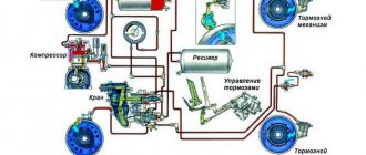
Kamaz trailer brakes
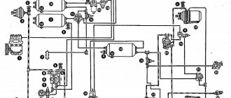
Design and operation of Kamaz trailer brake drive devices
The brake drive of a trailer (semi-trailer) of a tractor vehicle is combined (single-wire and two-wire),
includes a trailer brake control valve 6 with a two-wire drive, a single safety valve 2, a trailer brake control valve 9 with a single-wire drive, three disconnect valves 3 and three connecting heads - two heads 4 of the Palm type for a two-wire drive of the trailer brakes and one head 10 type A for a single-line drive of trailer brakes, pipelines and hoses connecting the devices.
The trailer brake drive is powered from receivers 1 of the parking and spare brake drive circuits.
The trailer brake control valve with a two-wire drive operates in the presence of two autonomous connecting lines - supply and control
It consists of three sections:
— the lower one (pin I) operates when the brake drive circuit of the front axle of the service brake system is operating;
— upper (terminal III) – when the brake drive circuit of the wheels of the rear bogie of the service brake system is operating;
- average (pin II) - when the brake drive circuit of the parking or spare brake systems is operating
In addition, there are two more terminals in the middle section: terminal V is connected to the air cylinder of the parking and spare brake systems; terminal IV - with a control line for a two-wire drive and a trailer brake control valve with a single-wire drive.
The valve controls the trailer brakes - supplies compressed air from the source (pin V) to consumers (pin IV) - with three independent commands acting simultaneously and separately; in this case, a direct action command is sent to terminals I, III (to increase the pressure when supplying air with a two-section brake valve), to terminal II - a reverse action command (to reduce the pressure when releasing air with a manual brake valve)
The main parts of the valve are: upper 5, middle 13 and lower 15 body (sections); large 6 and small 9 upper pistons with their own springs 10 and 8, respectively; middle piston 12 with inlet valve 4, constantly pressed by a spring to the piston seat, and rod 14; exhaust valve 11; unloading hole 3.
In the braked position (Fig. 2 b), compressed air is constantly supplied to terminals II and V, which, acting from above on diagram 1 and from below on piston 12, holds rod 14 together with piston 12 in the lower position, since the area of the diaphragm is larger than the area of the piston
In the upper part of the housing, the pistons 6 and 9, under the action of the spring 10, are in the uppermost position and the exhaust valve 11 is torn off from the seat made in the valve 4, and the inlet valve 4 is closed under the action of the spring 2. In this case, the IV output through the relief holes 3 of the valve and rod
When braking (Fig. 2, c), compressed air from the brake valve section is supplied to terminals I and II. Under the action of compressed air supplied to terminal I, rod 14, together with the middle piston 12 and valve 4, moves upward. Compressed air supplied to terminal III moves the upper pistons 6 and 9 down, compressing the spring 10. In this case, the exhaust valve 11 sits in the valve seat 4, disconnecting terminal IV from the atmospheric terminal VI, and then lifts valve 4 from the seat of the middle piston 12
Compressed air from terminal V, connected to the air cylinder, flows to terminal IV and further into the trailer brake control line until the force from the air pressure on piston 9 from below is balanced by the force acting on piston 9 from above, developed by the compressed air pressure and springs 8, and the force from the air pressure on the middle piston 12 will not be balanced by the force from the air pressure acting on the diaphragm 1 from below, i.e., tracking pressure is applied
When braking (Fig. 2, b), compressed air is removed from terminals I and III through an atmospheric hole in the brake valve. Pistons 6 and 9, under the action of spring 10 and compressed air, occupy the upper position, rod 14 with piston 12 – the lower position. Valve 11 is detached from valve seat 4 and communicates terminal IV with atmospheric terminal VI
When compressed air is supplied to terminals I or III separately, the rod 14 with the piston 12 moves upward, or the large 6 and small 9 pistons move downwards. Braking and deceleration occurs in the same way as already described
When braking with the spare or parking brake system of a car (Fig. 2, d), compressed air from outlet II is released into the atmosphere through an atmospheric hole in the reverse-action manual brake valve. The pressure above the diaphragm 1 drops and thereby reduces the force acting on the diaphragm and with it on the rod 14 and the piston 12 from above. Under the influence of constant pressure of compressed air supplied to terminal V, piston 12 together with rod 14 moves upward. In this case, valve seat 4 rests against valve 11, disconnecting terminal IV from the atmosphere, and then valve 4 is torn off from the piston seat 12 and terminal IV communicates with terminal V. Compressed air enters the controlled line of the trailer
The pressure in the trailer brake control line increases until the force acting on piston 12 from below is balanced by the force acting on diaphragm 1 and piston 12 from above, which ensures the follower action of valve 4
When compressed air is supplied to terminal III or simultaneously to terminals III and I, the pressure in terminal IV connected to the trailer brake control line exceeds the air pressure supplied to terminal III by 20-100 kPa (0.2-1.0 kgf/ cm 2), which ensures the advanced action of the trailer (semi-trailer) brakes. The excess pressure is regulated by screw 7 (Fig. 2, a): when the screw is screwed in, the excess increases, when turned out, it decreases.
Definition
What is a trailer brake valve and what is it for? The trailer brake valve is, perhaps, the main “control” element in the brake system of a pneumatically driven trailer. When you press the brake pedal, compressed air is supplied by a pneumatic valve to special brake chambers, due to which braking occurs.
Large vehicles, as well as other wheeled vehicles, are often equipped with a pneumatic braking system, which, both in terms of reliability and efficiency, is several times superior to hydraulic trailer brakes. The brake system is controlled by the brake valve and trailer brake control valves.
The trailer braking system works as follows:
- By supplying compressed air to the chambers, braking occurs;
- When pressing the brake pedal, the trailer valve regulates the force proportional to the degree of depression and the force on the pedal, so that the driver can clearly control the braking progress;
- If the trailer is equipped with a two-section brake valve, it ensures smooth operation between the two circuits if air passes from one section to the other.
It is thanks to the brake valve that the entire system is controlled in any driving mode, therefore, this element is extremely important for the normal use of the trailer. If the faucet fails, it must be replaced or repaired.
If you operate a trailer with a faulty crane, this can lead to an emergency while driving. If you need to completely replace this element, you should carefully understand the existing types of trailer brakes, as well as the design, and directly the principle of its operation.
Malfunctions
There are a number of problems that can reduce the effectiveness of your brakes. A trailer brake control valve repair kit may be needed in the following cases:
- After disconnecting the heads in the main line and opening the isolation valve, air from it does not flow to the tractor.
- When the disconnect valve is open, the air mixture flows from the head into the tractor line, but after connecting the elements of the tractor and the trailer distributor, the flow stops.
- When the brakes are activated, the brakes on the vehicle work, but the brakes on the semi-trailer do not.
- In the case when air comes out of the head during braking.
- During the release of the brakes, the wheels of the tractor react, but remain in a braked state on the towbar.
Spare part trailer brake control valve with two-wire drive MAZ, KamAZ
Purpose: Designed to control the brake system of a trailer with a two-wire drive. If the control brake line of a trailer breaks, the compressed air supplied from the vehicle to the trailer is blocked, with a simultaneous reduction in the pressure of the supply line. Available in two versions. A design feature of version 6024.35.22.010-10 is the installed muffler* 8088.00.00.000 TU RB 100185185.060-2001, designed to reduce the noise level when releasing compressed air into the atmosphere.
Description of operation: The supply line from the tractor receiver is connected to terminal 11 of the valve (Fig. 1), and the supply line of the two-wire trailer drive is connected to terminal 12. Pin 22 is connected to the control line of the two-wire drive, pins 41 and 42 are supplied with compressed air from both sections of the brake valve (that is, from the drive circuits of the tractor's service brake system), and pin 43 is connected to the manual reverse-acting brake valve (that is, with drive of the spare and parking brake systems). Pin 3 is atmospheric. When the vehicle is disengaged, compressed air from the tractor's receiver passes through terminal 11 to terminal 12 and then into the supply line of the trailer. Compressed air entering port 43 from the reverse-acting manual brake valve holds the middle piston 6 in its lowest position. When braking by the vehicle's working brake system, compressed air enters terminals 41 and 42. Pistons 8 and 9 move down, valve 5 opens and the trailer brake control line connected to terminal 22 is filled with compressed air. The pressure increase in terminal 22 continues until the pressure from below on pistons 8 and 9 will not balance the pressure coming from pin 41 on these pistons from above. An equilibrium position arises. In this way, a tracking action is carried out. When the brakes are released, the pressure in ports 41 and 42 decreases and pistons 8 and 9 move upward, closing valve 5. Air is released from port 22 into the atmosphere through port 3. When braking with the parking or emergency brake system, air is released from port 43. Piston 6 rises up to the stop against the piston seat 9. Valve 5 opens and the trailer brake control line is filled. The tracking action is achieved by balancing the pressure of compressed air from below on piston 6 and the sum of pressures from above on piston 6 and diaphragm 13. If the control line is damaged or depressurized, the pressure in cavity A begins to drop during braking, piston 10, under the influence of pressure in cavity B, moves down and shuts off supply line connected to terminal 11. As a result, the pressure in terminal 12 also begins to drop, since air from the trailer supply line connected to terminal 12 escapes into the atmosphere through damage to the control line. The trailer quickly self-brakes.
What is a trailer/semi-trailer brake air distributor?
The trailer/semi-trailer brake air distributor (air distribution valve) is a monitoring and control component of the brake system of trailers and semi-trailers with pneumatic drive. A unit with a system of channels and valves that ensures the distribution of compressed air flows between system components.
The air distributor is designed to control a road train and a separate trailer/semi-trailer:
• Braking and release of a trailer/semi-trailer as part of a road train; • Trailer/semi-trailer braking when disconnected from the vehicle; • Release the brakes of the trailer/semi-trailer when maneuvers are necessary without being connected to the tractor; • Emergency braking of the trailer/semi-trailer when separated from the road train.
All cargo trailers and semi-trailers are equipped with brake air distributors, but they differ in purpose, type and design, which needs to be discussed in more detail.
KAMAZ trailer braking system
KamAZ trailer air distributor
disconnecting the trailer brake control valve
Pneumatic braking system
Air leak from the brake valve KAMAZ ZIL PAZ MAZ KRAZ GAZ
How the WABCO ABS pneumatic braking system works
Brakes jam on KAMAZ ZIL GAZ PAZ LAZ MAZ. Brake valve repair.
CONVERTING BRAKE SHAFTS FOR BEARINGS (FRUEHAUF, BPW, ROR, SAF)
- Replacing a KAMAZ vehicle engine
- Rem dimensions of KAMAZ shaft
- Buses on KAMAZ Ural chassis
- KAMAZ cylinder head
- KAMAZ cabs with sofa
- Transferring fuel from tank to tank on a KAMAZ
- Soars from the breather onto a hot KAMAZ
- There is no reverse gear on KAMAZ
- KAMAZ fits the platon
- Standard time for KAMAZ maintenance
- How to properly remove the box on a KAMAZ
- KAMAZ windshield wiper blade size
- Adjusting the steering wheel KAMAZ 53215
- Shock absorber KAMAZ 5312
- How much does KAMAZ consume when idling?
Home » Popular » KAMAZ trailer braking system kamaz136.ru
Types and applicability of brake air distributors
Air distributors are divided into groups according to the type of pneumatic drive of the brake system in which they can operate, and the configuration.
There are three types of air distributors:
• For single-line brake systems; • For two-wire brake systems; • Universal.
Single-line trailer and semi-trailer brakes are connected to the vehicle's air system with one hose. With its help, both the tanks of the trailer/semi-trailer are filled and the brakes are controlled. Two-line brake systems are connected to the tractor pneumatic system by two lines - the supply line, through which the trailer's receivers are filled, and the control line.
To operate in a single-line brake system, air distributors with a follower mechanism are used, which monitors the pressure in the line and, depending on it, supplies compressed air from the trailer’s receiver to its brake chambers.
To operate in a two-wire system, air distributors with a separate tracking mechanism are used, which monitors the pressure in the control line and, depending on it, controls the air supply from the receivers to the components of the trailer/semi-trailer braking system. Universal air distributors can work in both single- and two-line brake systems.
Design and principle of operation of brake air distributors
Today, a large number of models of air distribution valves for trailers and semi-trailers are produced, but they all have a fundamentally identical design. The unit combines several pistons and valves that switch the line from the tractor, the receiver and the wheel brake chambers, depending on the condition of the brake system of the tractor. Let's consider the design and operating principle of a universal (used in both single- and 2-wire brake systems) air distributor for KAMAZ trailers with a separate brake release valve.
Let us immediately note that the air distributor controls the trailer braking system only when using the main braking system of the tractor. If your tow vehicle is equipped with a backup or parking brake system, a solenoid valve controls the air supply to the trailer brake system components. We will not consider the operation of this node here.
KAMAZ how to remove the trailer crane
disconnecting the trailer brake control valve
How to remove the main brake valve on a Kamaz 5511 car
KamAZ trailer air distributor
Repair of trailer crane and generator.
Air leak from the brake valve KAMAZ ZIL PAZ MAZ KRAZ GAZ
Wabco air distribution valve.
Trailer brake control valve
KAMAZ accelerator valve
Trailer brake control valve.
- KAMAZ 740 cylinder head bolt tightening diagram
- Gur KAMAZ 45143
- How to make the front of a KAMAZ truck softer
- Video tutorials on KAMAZ repairs
- Fire truck KAMAZ 43118 diagram
- Overview of the KAMAZ 5460 cab
- Dump truck KAMAZ 5510 technical characteristics
- Tie rod KAMAZ longitudinal rostar
- Tataria KAMAZ plant
- KAMAZ results of the first quarter of 2015
- Engine KAMAZ 11113
- How to properly adjust valves on KAMAZ video
- Standards for repairing KAMAZ vehicles
- KAMAZ is the master of whose engine
- How to change gears on a KAMAZ vehicle video
Home » Clips » KAMAZ how to remove the trailer crane kamaz136.ru
Connection diagram for KAMAZ brake trailer valve
disconnecting the trailer brake control valve
KamAZ trailer air distributor
Air leak from the brake valve KAMAZ ZIL PAZ MAZ KRAZ GAZ
Wabco air distribution valve.
11.3531010-70 air distributor connection
11.3531010-70 air distributor
Repair of trailer crane and generator.
KUTP 1 TRAILER BRAKE CONTROL VALVE WITH SINGLE WIRE ACTUATOR ZTD
We install the KAMAZ accelerator on Foton 1093
air distributor 11.3531010-81.80 PAAZ connection
Also see:
- How to change gears on a KAMAZ dump truck
- KAMAZ dump truck 2012
- How to seal the casing on a KAMAZ
- Mode of part-time working KAMAZ
- Wedge disks for KAMAZ
- KAMAZ vehicles characteristics
- Installation of a Bosch fuel pump on KAMAZ
- Installation of a turbine on KAMAZ 53212
- KAMAZ trucks what category is needed
- KAMAZ design projects
- Disaster with KAMAZ
- Steering rod repair kit KAMAZ 4310
- Brake system of the KAMAZ 5310 vehicle
- Firefighter rapid response vehicle based on KAMAZ
- Air sensor KAMAZ
Home » Video » Connection diagram for the KAMAZ brake trailer valve
kamaz-parts.ru
Operation of the air distributor with a two-wire air distributor circuit
Two lines from the tractor are connected to the air distributor - the supply line to pipe I and the control line to pipe V. The remaining pipes have a connection similar to a single-wire circuit. Also, with a 2-wire circuit of the pneumatic drive, equalizing valve 10 comes into operation. With this connection circuit, a higher pressure is supplied to pipe I than with a single-wire circuit, which makes it difficult for the piston 2 to move and disrupts the operation of the entire brake system. This problem is eliminated by an equalizing valve - at high pressure it opens and connects the cavities above and below the piston, equalizing the pressure in them.
Connection of a trailer/semi-trailer with a tractor. Road train movement. In this case, air from the supply hose fills the receivers through pipes I and IV; the remaining components of the air distributor do not work.
Braking a road train. When the tractor is braked, the pressure at port V increases, compressed air enters the chamber above the piston 11, forcing it to move down. In this case, the processes described above occur - valve 5 closes, valve 7 opens, pipes IV and III are connected, and air from the receivers enters the brake chambers, performing braking.
Release of the brakes of the road train. When the tractor is released, all processes occur in the reverse order: the pressure on pipe V drops, the piston rises, pipe III connects to pipe II, the air is released from the brake chambers and the trailer is released.
Emergency braking in case of a line break, trailer disconnection. In these cases, the role of the tracking mechanism is performed by the equalizing valve. When the pressure on pipe II drops to atmospheric pressure, the valve closes, separating the chambers above and below piston 2. As a result, the pressure above the piston (due to the air coming from the receivers through pipe IV) increases, and processes similar to braking with a single-wire connection scheme occur. Thus, in the event of a rupture/disconnection of a hose or when the road train disassembles, the trailer/semi-trailer is automatically braked.
Valve operation during braking
The valve of the KamAZ trailer brake control valve supplies compressed air from the sections of the device to the terminals when braking. From the other outlet of the air tank, the compressed mixture flows to the control terminal, after which it is sent to the main part. There, the air acts on the piston until it is balanced at the bottom under the upper pressure. The upper piston operates under the force of air pressure and spring. In this case, the middle piston must also be balanced under the influence of identical factors. In principle, a general tracking action occurs.
When the brakes are released, compressed air is discharged through the atmospheric opening of the valve from the filled compartments. The pistons, under the pressure of the spring and the air mixture, move to the upper position, and the rod with the piston moves down. The valve comes off the seat and connects the internal and external inlet.
Suitable compressed air causes the rod and piston to move separately upward, and the large and small piston element downward. Subsequent operation of the brakes follows a similar principle.
When the truck's backup or parking system is activated, compressed air is drawn through the atmospheric port in the manual return valve and released to the outside. The degree of pressure above the diaphragm decreases, reducing the force on the working elements. The seat rests on the valve, separating the outlet from the atmosphere. Then the valve opens, communicating between the outlet and the main line.
Design and principle of operation of the brake release valve
The CD has a simple structure and operation. Let's consider the functioning of this unit using the example of a trailer crane from the Kama Automobile Plant.
The unit can be installed directly on the air distributor housing or located nearby in a more convenient location. Its pipe I is connected to the trailer/semi-trailer receiver through the air distributor channel or a separate pipeline. Pipe II is connected to pipe I of the air distributor, and pipe III is connected to the car's main line.
During the main operation of the trailer, rod 1 is in the upper position (it is fixed in this position by means of spring-loaded balls that rest against recesses in the body of the device), air from pipe III flows to pipe II, and port I remains closed, so the valve has no effect for the operation of the air distributor.
If it is necessary to move the uncoupled trailer, you need to move rod 1 down using the handle - this will lead to the separation of pipes II and III and the connection of pipes II and I. As a result, air from the receiver is directed to the inlet I of the air distributor, the pressure on it increases and processes similar to to the release processes with a single-wire pneumatic drive circuit - the trailer is released. To brake, you must return the rod to the top position.
KAMAZ trailer air distributor device | KAMAZ
KamAZ trailer air distributor
Brake air distributor Design and operation
disconnecting the trailer brake control valve
11.3531010-70 air distributor connection
Air leak from the brake valve KAMAZ ZIL PAZ MAZ KRAZ GAZ
air distributor 11.3531010-81.80 PAAZ connection
How does an air brake system work?
- Cummins engine for KAMAZ power
- Removing timber on your KAMAZ
- Engine KAMAZ 570
- Front towing hook KAMAZ
- Video under the wheels of KAMAZ
- KAMAZ container truck body volume
- Mounting the mirror on KAMAZ
- KAMAZ 4 axle 20 cubic meters
- How to install a Cummins engine on a KAMAZ
- KAMAZ 65117 frame repair
- Laugh about KAMAZ trucks
- The largest KAMAZ plant
- Repair instructions for KAMAZ 53229
- Antifreeze went into KAMAZ oil reasons
- Oil scraper caps KAMAZ
Home » Selections » KAMAZ trailer air distributor device kamaz136.ru
Selection, replacement and maintenance of the brake air distributor
The brake air distributor is constantly subjected to high loads; gaps in its moving parts increase, which can cause air leaks, poor performance, or, on the contrary, spontaneous brake application. In case of any problems, it makes sense to replace the assembly.
When choosing an air distributor, you should follow the recommendations of the trailer manufacturer and install units of certain models and catalog numbers. However, today the market offers a wide selection of original air distributors and their analogues with improved characteristics. Therefore, in a number of cases, it may be justified to install an analogue, but in order to avoid problems in the future, it is necessary to choose analogues with suitable connection dimensions and characteristics.
With the correct selection and installation of the air distributor, the brakes of a trailer or semi-trailer will work reliably and efficiently in any conditions, ensuring the safety of the road train.
Source