1. The heater operates independently of the car engine. It is the main component in the vehicle engine coolant heating system. 2. The heater is started and turned off “manually” using the control panel.
Fig. 1 Electrical connection diagram of the PRAMTRONIK 16ZhD-24 heater
3. The heater is controlled by a control panel, which is located on the vehicle dashboard. On the front panel of the remote control there is a potentiometer knob position 1 (Fig. 2) for setting the air temperature inside the car. The temperature can be set from +15 °C to +30 °C (one division on the remote control panel corresponds to a temperature increase of 3 °C). On the front panel of the remote control, there is a Pr1 button (item 2) and a Pr2 button (item 3). The buttons are designed to turn the heater on and off according to program 1 and program 2, respectively. The buttons are illuminated in green, which indicates the presence of voltage in the heater power circuit. The front panel of the control panel also displays LEDs pos. 4 and pos. 5 (see Fig. 2), which show the state of the heater and the program according to which the heater operates (see Table 2).
Rice. 2 Control panel
| Indication | Heater condition |
| No indication | Heater is off |
| Green glow of LEDs pos.4 or pos.5. | The heater operates according to program 1 or program 2, respectively |
| Short flashing of the LED pos. 4 or pos. 5 in red, accompanied by a sound signal. | A malfunction has been detected in the heater |
| Three-time short-term flashing of LEDs pos. 4 and pos. 5 in red light. | The heater is in blocking mode |
4. After pressing the Pr 1 or Pr 2 button to start the heater, the control unit diagnoses all elements of the control system and their power circuits. If all elements are in good condition, the control unit starts operating the heater according to the specified program; when you press the Pr 1 button (pos. 2), the heater starts working according to program No. 1, and when you press the Pr 2 button (pos. 3), according to program No. 2.
5. If for some reason the heater does not start, the process of starting the heater is automatically repeated. After 2 unsuccessful attempts to start the heater, it automatically turns off. At this time, the heater is purged for 3 minutes. This purge is carried out when any malfunction of the heater occurs. After the purge is completed, the electric pump is turned off. The fault code is displayed and signaled for 10 minutes. The fault codes are shown in Table 3. The fault code can be cleared with the corresponding program button by pressing and holding it pressed for 5 seconds. 6. When you press the Pr 1 button (item 2), the heater operates according to program No. 1, which provides for quick preparation (heating) of the engine for starting. When the temperature reaches +80 °C, the heater goes into standby mode, i.e. heating of the coolant stops, and the electric pump continues to operate. The heater operation indication is on at this time. The “standby” mode continues until the coolant temperature drops to +55 °C. When this temperature is reached, the control unit starts the heater and runs program No. 1 again. The heater can be turned off at any time during operation by pressing the Pr 1 button (item 2) again, or switched to program No. 2 by pressing the Pr 2 button (item 3). When the heater is operating according to program No. 2, the control unit, based on a signal from the incoming liquid temperature sensor, when the liquid reaches a temperature of +40 ° C, turns on the cabin heater fan (if the heater is normally connected to the vehicle), begins heating the air in the cabin and maintaining the air temperature, which set on the control panel. The heater automatically maintains the set temperature in the car cabin. The temperature in the car cabin is measured:
- remote temperature sensor A7 (Fig. 1), which must be installed in a place where it is necessary to maintain the set temperature. The remote sensor must be well blown with air (additional option);
- temperature sensor built into the heater control panel.
The temperature is adjusted by turning the cabin heater fan on and off. When the temperature reaches +70 °C, the heater goes into standby mode, i.e. heating of the coolant stops, and the electric pump continues to operate. The heater operation indication is on at this time.
When the temperature reaches +40 °C, the control unit turns on the heater and program No. 2 is executed again.
1. On the control panel the buttons Pr1 (item 2) and Pr2 (item 3) are not illuminated (see Fig. 2). Check the presence of supply voltage (Unom=24 V) in the XS3 car block (see Fig. 1).
- Check for open circuit and, if necessary, replace the 15 A fuse in the heater power harness. A fuse can blow due to a short circuit in the vehicle's on-board network.
- Check for an open circuit in the power supply and the condition of the contacts in the connectors of the harnesses connecting the remote control (A 3) and the heater (A 2).
If the above elements are in good condition, replace the control unit. 2. All possible malfunctions that may arise during the operation of the heater are displayed in the form of fault codes on the control panel. Each fault code is displayed in the form of repeated flashes and pauses of the LED pos. 4 or pos. 5 (see Fig. 2) (red) and is accompanied by a sound signal.
Malfunctions and their elimination
The organization of searching for defects is described in the operating instructions for the device. Malfunctions that arise during operation and require complete or partial disassembly of the heater must be carried out by specialists from repair organizations. All faults, except the inability to turn on the heater, are indicated by a blinking LED on the control panel.
Error codes
The heater is equipped with a monitoring system for the proper operation of components and individual elements. If a defect occurs, the automation classifies it and notifies the driver by the number of LED flashes. The list of possible malfunctions is summarized in a table indicating the necessary actions to be taken to restore the device to operability. Error codes correspond to the number of blinks of the indicator.
Malfunctions are collected into 10 groups based on the same causes of occurrence and methods for eliminating defects. The table is given in the heater operating manual.
You can find out about the error by the indicator on the timer-thermostat or control panel.
Timer error codes:
On the control lamp, the same errors are identified by the number of blinks, and their number corresponds to the error code. For example, if the indicator blinks 4 times, then there is a malfunction in the flame indicator circuit (E-04).
If error E-20 occurs, the indicator lamp will not blink.
Error codes on the control panel are indicated by a sound and light signal: the indicator begins to flash red. The number of times the sound and color signals are the same, for example, the error code corresponds to 02 flashes of the indicator and 2 sound signals.
Error codes: 01 - flame failure 02 - no ignition 03 - high voltage 04 - low voltage 05 - temperature sensor failure 06 - flame indicator circuit failure 07 - electric pump failure 08 - solenoid valve failure 09 - burner motor failure 10 - problems in the high-voltage source voltage 11 – no connection with the control unit 12 – thermal fuse trips 13 – fuel heater transistor is broken
Why doesn't it start
If, when you try to turn on the heater, the LED indicator does not light up and the start-up does not occur, then there may be several reasons for this situation, but they are all related to a lack of power:
If there is power to the control panel, the cause of the malfunction may be a defect in any of the controlled elements. In this case, the defect code will be shown by a flashing indicator.
How to turn it on
Starting and changing operating modes of the “autonomy” are carried out from the control panel. To start the heater, you need to select a program using the mode key (3 or 8 hours) and turn on the power switch. The LED will light up and the control unit will begin executing the program. After testing is completed and the blower, pump and fuel pump are turned on, the burner will ignite. The program runs automatically and does not require driver intervention. At the end of the set time, the device will stop.
Restart is possible after a power failure; its subsequent activation - no earlier than after 10 seconds.
Control panel design
The remote control is used to manually control the heater modes, to extend the operating time, as well as to turn it on and off.
Remote panel drawing:
One switch is used to turn on/off, the second to control operating modes.
The thermostat knob is used to regulate cabin heating, which is carried out when the coolant temperature is above 55°C.
If the LED indicator is flashing, then there is a malfunction in the preheater; stable lighting indicates that the system is working
Repair
Despite the fact that the manufacturer recommends repairing breakdowns associated with disassembling an autonomous heater in specialized workshops, many drivers and car owners prefer to fix the faults themselves. The fairly high price of the work pushes them to this decision.
Most often, the flame sensor fails and the fuel line becomes clogged. The work is simple and does not require the use of special tools.
Regular scheduled maintenance will help reduce the number of defects.
For this type of heaters, there are 2 types of maintenance: daily and seasonal. The volumes, timing and list of work performed are given in the technical documentation for the device.
Do-it-yourself repair of PZD 14TS-10
Car owners are asking the question: is it possible to repair the PZD with your own hands? It all depends on the complexity of the breakdown: some faults are easy to fix yourself, others can only be fixed by a specialist.
Before repairs, it is necessary to carry out diagnostics: set the error code and the possible cause of the malfunction.
For example, if the voltage is low, the problem is most likely in the voltage regulator; you either need to replace it or check the contacts.
If the flame fails, the source of the problem may be clogged filters, poor-quality gas exhaust or air injection.
If the cause has been established, but the situation cannot be corrected, then it is better to contact a specialist, because poor-quality repairs can further aggravate the problem.
Pramotronik 12ZhD24, 16Zh24, 24.8106
| Flashing | Malfunction | Recommendations for elimination |
| 1 | The battery voltage is not normal. | Check the voltage at the connector. The voltage should be from 20÷30 V. If the voltage is less than 20 V, charge the battery or replace it; if it is more than 30 V, check the voltage regulator. |
| 2 | Two startup attempts were used. | Check the presence of fuel in the fuel tank, disconnect the fuel line from the heater and check the fuel supply, if there is no fuel, check the operation of the fuel pump, replace if necessary. Check the air intake filter and exhaust pipe for blockages. |
| 3 | Flame interruption in the combustion chamber. | Check the amount of fuel supplied. Check the air intake filter and exhaust pipe for blockages. If the heater starts and turns off, check the flame indicator and replace if necessary. |
| 4 | Electric pump malfunction. | Check the electric motor circuit with the harness for open circuit and short circuit. The resistance between the terminals should be ~1 Ohm. |
| 5 | Fuel pump malfunction. | Check the fuel pump harness for opens and short circuits without disconnecting it from the pump. The resistance between the terminals should be ~ 20 Ohms. |
| 6 | Ambient temperature sensor circuit malfunction. | Check the connector connecting the remote control and the ambient temperature sensor, check the harness for a break. |
| 7 | Blower motor circuit malfunction. | Check the motor circuit and replace the air blower if necessary. |
| 8 | Faulty glow plug. | Check the spark plug chain. Resistance should be ~2 ohms. |
| 9 | Lack of communication with the control panel. | Check the connector connecting the control panel to the heater control unit. |
| 10 | Malfunction of the incoming fluid temperature sensor circuit. | Check the connector connecting the sensor to the control unit, check the harness for a break. |
| 11 | Outgoing fluid temperature sensor circuit malfunction. | Check the connector connecting the sensor to the control unit, check the harness for a break. |
| 13 | Heat exchanger overheating. | Check the electric pump, the presence (level) of coolant, and the absence of air pockets in the liquid system. |
Design and operating principle of 14TS-10
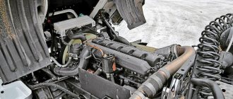
The 14TS 10 device is a special device built into a break in the circuit of the engine liquid cooling system. Structurally, it consists of a housing in which a combustion chamber, a built-in heat exchanger and an electric pump are located. Switching on and monitoring the operation of the heater is carried out by a control unit with a remote control. The heater is connected to the fuel system and on-board electrical network of the vehicle.
When fuel burns in the heater chamber, heat is released, which is transferred to the heat exchanger. The liquid passing through it is heated and, with the help of a built-in pump, circulates in the engine water cooling system.
The camera operation process is controlled by a combustion indicator. Having reached the specified heating temperature limit (80°C), combustion stops and the device begins to cool down. The heated liquid continues to circulate in the system.
Automatic operation of the 14TC-10 is carried out according to one of the selected programs: economical or pre-start. In the first case, the operating cycle lasts 8 hours at low power, in the second, heating occurs in 3 hours at maximum power.
Pramotronik 30ZhD24, 35Zh24, 141.8106
Decoding errors
1 — Flame failure during heater operation
Causes
2 - Heater does not start
Causes
3 - Supply voltage does not meet specified limits
Causes
4 - Supply voltage does not meet specified limits
Causes
7 - Heater does not start
Causes
8 - Solenoid valve circuit malfunction
Causes
Other faults
No voltage
Lamps HL1 and HL2 do not light up when the heater is turned on.
Causes
How to use a KAMAZ autonomous vehicle
Pzh14TS TS 10(GP) Kamaz Omsk How air auxiliary heaters work
Video instructions for using the EasyStart Timer control unit (weekly) from Eberspacher.
malfunction of pre-heater 14TS-10 Kamaz
Setting up the Planar remote control
AUTONOMY AND PRE-HEATER - TWO IN ONE
WEBASTO for trucks
How to revive the autonomous (webasto) Volvo Fh
autonomous stove KAMAZ
General signs of malfunction of Pramotronic flare heaters
| Symptoms of a problem | Possible reasons |
| The heater does not start. | There is no voltage supply, the connection polarity is reversed. |
| There is no ignition. | Lack of fuel. |
The fuel pump is not working.
The solenoid does not open.
The injector is clogged, the connection of the fuel lines is leaking (the pump sucks in air).
Incorrect fuel spray angle, less than 80º.
Low motor speed.
Pramotronik 143.8106
The HG27 lamp does not light up when the heater is turned on.
Poor contact in electrical connections.
Break in the power supply circuit using thermobimetallic fuse FU25.
Poor contact at the battery terminals.
Break in the heater power wiring harness.
The polarity of the heater power wires on the battery is reversed.
Poor contact in electrical connections.
The fuel filter is clogged.
The tightness in the supply line of the heater fuel line is broken.
Thickening of fuel in the fuel line during climate change.
Flame failure during heater operation.
The tightness in the supply line of the heater fuel line is broken.
Solidification of fuel in the fuel line during climate change.
Solenoid valve circuit malfunction.
Solenoid valve circuit malfunction.
The heat exchanger overheated, the heater thermal fuse tripped.
10The supply voltage does not meet the specified limits. The ATC voltage regulator is faulty. 3The supply voltage does not meet the specified limits. The battery is discharged.Preheater 14TS-10
PZD 14TS-10 prepares the engine for operation by heating the coolant.
This type of preheater has several heating modes:
And also 2 heating programs:
In full mode, the pre-start program warms up the liquid to 70°C, in economy mode – up to 55°C. After reaching the highest temperature, the PZD switches to the “medium” mode, in which the liquid is heated to 75°C, and then to the “small” mode: in it the maximum temperature of 80°C is reached. Next, the heater goes into cooling mode.
Electrical diagram
The heater operates from a battery and is also powered by diesel fuel. It is the electrical circuits of the heater that provide automatic and remote control through the unit and control panel.
When overheated, the system automatically turns off. Also, when the voltage decreases to 20 W or increases to 30 W, the preheater turns off. In addition, the PZD switches off after two unsuccessful startup attempts; If the combustion stops during operation, the system turns off.
Connection diagram for the electrical circuit 14TS-10:
Control panel 27.3854 (15.8106, 151.8106)
| Code | Number of long flashes, LED color | Number of beeps | Malfunction |
| – | There is no glow. | – | The heater is turned off. |
| 00 | The LED glows green constantly. | – | The heater starts and works. |
| 01 | 1 red | 1 | Flame failure. |
| 02 | 2 red | 2 | No ignition. |
| 03 | 3 red | 3 | Supply voltage is higher than 30 V. |
| 04 | 4 red | 4 | Supply voltage is below 20 V. |
| 05 | 5 red | 5 | Temperature sensor circuit malfunction. |
| 06 | 6 red | 6 | Flame indicator circuit malfunction. |
| 07 | 7 red | 7 | Electric pump malfunction. |
| 08 | 8 red | 8 | Solenoid valve malfunction. |
| 09 | 9 red | 9 | Burner motor malfunction. |
| 10 | 10 red | 10 | Malfunction of the high voltage voltage source. |
| 11 | 11 red | 11 | Lack of communication with the control unit. |
| 12* | 12 red | 12 | The thermal fuse has tripped. |
| 13* | 13 red | 13 | Faulty circuit (transistor broken) of the fuel heater. |
The manufacturer strongly recommends that if malfunctions occur, contact specialized service centers and not carry out repairs yourself.
Source
Control unit and control panel
The block performs three options: performs primary diagnostics and checks errors during operation; starts the heater and operates it in economy or pre-start mode; turns off the device due to inoperability of the components or some parameter that has exceeded its limit, as well as due to flame failure.
Using the remote control, you can control the autonomy - turn it on and off manually, set the heating time and control the ventilation system in the cabin. Instruction 14TS-10 is not complicated, but you need to study it. All actions are performed using the panel .
It has 2 switches, an LED and a thermostat knob.
The remote control will help you with control
Pramotronik 143.8106
Decoding errors
1 — Flame failure during heater operation
Causes
2 - Heater does not start
Causes
3 - Supply voltage does not meet specified limits
Causes
7 - Malfunction of the solenoid valve circuit
Causes
9 - Heater does not start
Causes
10 - Supply voltage does not meet specified limits
Causes
Other faults
No voltage
The HG27 lamp does not light up when the heater is turned on.
Causes
Source
Autonomous vehicle for Kamaz | Thread starter: Agne
We write about who had any troubles and how they dealt with them.
Andryukha (Jemeil) I have the same problem, the standard heater is wet, I recently read the instructions for it, and it turns out that you can turn on the heater in the cabin using the remote control for the heater. but no matter how much I turn the regulator on the remote control, the heater in the cabin still does not blow automatically. Maybe I can put a relay somewhere, or hook up the wires, tell me.
Yu (Shripati) and everything happened to her: the bullets failed and the circulation pump closed and the candle and brains died.
Heater Errors
Eberspacher 001 01 Voltage is less than rated - the heater is working 002 02 Voltage is higher than rated - the heater is working 004 03 Fan short circuit (D2I) 005 05 Alarm wire short circuit (D2I) 009 09 Heater switched off by TRS system (D2I / D9W) 010 0A Voltage is higher rated (heater stopped) 011 0B Voltage less than rated (heater stopped) 012 0C Overheating - fuel pump is turned off 013 0D Temperature sensor recorded high temperature 014 0E Large difference in t values. Dutch overheating and sensor regul. t (D3W / D9W) 015 0F The heater has overheated many times - the heater is turned off (D2I / D9W) 017 11 Repeated overheating (t has exceeded the 2nd response threshold) (D3W) 020 14 Glow plug / core is faulty 021 15 Short circuit of the plug / core Enjoyment 022 16 Failed candle / incandescent relay (d2W) 023 17 internal defect of the relay regulator R2 candle / incandescent rod 024 18 Short short circuit of the relay-regulator of incandescent 025 19 Diagnostic connector 029 1d air fan in position 5 does not work. R3 030 1E Air fan does not work in all positions (R3-D3W) 031 1F Air fan does not work in all positions (R3-D3W) 032 20 Air fan does not work in all positions (R3-D3W) 033 21 Air fan does not work in all positions (R4-D2I / D9W) 034 22 No contact with the cooling system solenoid valve. (D2W / D9W) 035 23 No contact with the average capacity relay 036 24 Short circuit of the average capacity relay 037 25 Water pump does not rotate (D2W / D9W) 038 26 No contact with the cabin heating fan relay (D2W / D9W) 039 27 Short circuit of the relay cabin heating fan (D2W / D9W) 040 28 Electromagnetic short circuit. cooling system valve (D2W / D9W) 042 2A Short circuit of the water pump (D9W) 043 2B Short circuit of the cable from the heater ECU to the fuel pump (D9W) 047 2F Short circuit of the fuel pump 048 30 No contact with the fuel pump 050 32 The heater started many times but did not work (relay R3) 051 33 Flame appeared immediately after pressing the heater start button 052 34 No start (purge restart) 053 35 Flame stops during start-up 054 36 Flame stops at max. performance 055 37 Flame stops in the medium performance position 056 38 Flame stops in the low performance position 057 39 Short circuit of the flame sensor (photoresistor) 058 3A Heater is off, but there is a flame in the combustion chamber (D2W) 059 3B Water temperature rises too quickly (D9W) 060 3C Нет контакта с датчиком регулировки температуры 061 3D Короткое замыкание датчика регулировки температуры 062 3E Нет контакта с потенциометром (D2H / D2I) 063 3F Короткое замыкание потенциометра (D2H / D2I) 064 40 Нет контакта с датчиком пламени 065 41 Короткое замыкание датчика пламени 071 47 No contact with overheat sensor (D3W / D9W) 072 48 Short circuit of overheat sensor (D3W / D9W) 073 49 Overheat sensor detected rapid temperature rise (D9W) 090 5A Spontaneous error 091 5B High voltage surge (high voltage wires, CB radio, etc.) 092 5C Heater ECU defective - ROM fault 093 5D Heater ECU faulty - RAM fault 094 5E Heater ECU faulty - EEPROM fault 096 60 Temperature sensor Heater ECU faulty (D2I) 097 61 Heater ECU faulty (D2I / D2) W/D9W) 255 FF Memory cleared but EEPROM faulty
Autonomous vehicle for Kamaz | Thread starter: Agne
We write about who had any troubles and how they dealt with them.
Andryukha (Jemeil) I have the same problem, the standard heater is wet, I recently read the instructions for it, and it turns out that you can turn on the heater in the cabin using the remote control for the heater. but no matter how much I turn the regulator on the remote control, the heater in the cabin still does not blow automatically. Maybe I can put a relay somewhere, or hook up the wires, tell me.
Yu (Shripati) and everything happened to her: the bullets failed and the circulation pump closed and the candle and brains died.
Principle of operation
The PZD is connected to the diesel engine cooling system. The system must be fully operational and filled with liquid in the required volume. When the diesel engine is turned on, fuel is supplied to its combustion chamber through a pump and a fuel pump and air, the fuel-air mixture ignites and begins to heat the engine cooling system liquid, which circulates around the combustion chamber body. The spent exhaust gases are discharged through its own exhaust system. After a few minutes, the temperature in the engine cooling system reaches an acceptable temperature for starting.
Recommendations
1. To ensure long-term operation of the heater, it is recommended to briefly turn on the heater for about 5 minutes once a month throughout the year (including during the warm period of the year). Switch on when the ambient temperature at the control panel and temperature sensor is below +30 °C. In this way, sticking of the moving parts of the fuel pump (which can occur from low-quality fuel) can be prevented. 2. Reliable operation of the heater depends on the fuel used depending on the ambient temperature. Recommended fuel types are shown in Table 2.
Purpose of the device
Unit features
For KAMAZ vehicles, autonomous liquid pre-heaters are used, which operate on diesel fuel. The main advantage of these variations is that they can provide effective engine warming up with minimal consumption.
Pre-heater KamAZ
It should also be noted that the device connects to the car’s electrical network, but does not consume a lot of electricity. It turns out that when using the KAMAZ preheater, the battery operates autonomously and does not require third-party power sources.
In more outdated truck models, simple devices of the 4310, 520 series are installed. These variations have a simple design and do not differ in complex installation schemes. Modern units are in great demand in new KAMAZ vehicles, buses, special equipment and tractors. But despite the difference in functions, the operating principle of the devices consists of standard steps.
VIDEO: Preheating a cold engine
Design and device
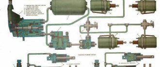
The design of the KAMAZ pre-heater includes several main components:
The main element is the boiler compartment, which consists of 4 durable cylinders that form a heat exchanger. This part includes 2 cavities that facilitate the unhindered passage of exhaust gas and coolant circulation. There are 3 tubes on the outer part of the engine heater, 2 of them are intended for draining or supplying antifreeze, one is for exhaust gas removal.
Pre-heater device
The exhaust gases hit the damped part of the boiler, which due to this action change direction and flow to the outlet pipe. In this case, thermal energy is consumed for heating in the engine sump.
On the reverse side, at the open end of the boiler compartment, a burner is mounted, which includes:
How to use a KAMAZ autonomous vehicle
Pzh14TS TS 10(GP) Kamaz Omsk
How do air auxiliary heaters work?
Video instructions for using the EasyStart Timer control unit (weekly) from Eberspacher.
malfunction of pre-heater 14TS-10 Kamaz
Setting up the Planar remote control
AUTONOMY AND PRE-HEATER - TWO IN ONE
WEBASTO for trucks
How to revive the autonomous (webasto) Volvo Fh
autonomous stove KAMAZ