Adjusting the Kamaz double-disc clutch
Incorrect clutch adjustment on a Kamaz vehicle. The cost of the issue is repeated removal of the gearbox. Or the agony of adjusting without removing the box. How to adjust the clutch This is an eternal question when installing a clutch basket. If you put a basket every day, there is no doubt. There are very important issues that it is better to know about when installing the clutch basket.
How to know when it's time to change your clutch
There are cases when adjusting the clutch cannot correct the problem. Perhaps you missed a moment when you could get by with little effort, or maybe the device failed for some objective reason. So, it’s time to change the MAZ clutch if you notice the following signs:
- The device turns on abruptly, the car jerks and abruptly pulls away.
- Noise in the mechanism, perhaps a loud cracking sound when the gear is engaged.
- The car starts moving late, even if you release the clutch on time.
- A characteristic burning smell in the cabin (this is a clear sign that the clutch has burned out).
There is no need to delay replacing the clutch. As a result, everything may end in damage to the gearbox or in the fact that one fine day the car simply will not be able to move.
However, if you are confident in your abilities or the KamAZ clutch basket is familiar to you, you can get down to business.
What you need
Before starting work, you need to stock up on a certain set of tools. So, you will need:
- A set of wrenches or socket heads.
- Emphasis.
- A ruler to later measure the free play of the pedal.
- Pliers and pliers.
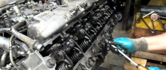
Replacing the Kamaz clutch
If you have all this, it's time to get to work. The main thing is to strictly follow the entire sequence of actions:
- First of all, remove the gearbox. KamAZ has it very heavy, so you will need the help of several people.
- Next, next is the clutch basket, remove it too.
- Then remove the driven, middle and driving clutch discs.
- Then install new parts of the device in their place. Start by installing the first driven disk and then install the parts in the reverse order of disassembly.
- Make sure once again that the device is assembled correctly and that’s it – you can put the gearbox in place.
If the clutch is single-plate, the process is similar and even easier. It may seem that everything is quite simple, but this is far from the case. Replacing and adjusting the MAZ clutch will require a lot of physical effort and time. Perhaps it makes sense to trust specialists who will do everything correctly and without mistakes. By observing the process, you will be able to remember the entire sequence in practice, and next time you will be able to adjust or replace the device yourself.
How to use the clutch to make it work as much as possible
There are several simple rules to extend the life of the KamAZ clutch. Unfortunately, not all drivers use them and often the device has to be changed much earlier than provided by the manufacturer.
- Do not keep the mechanism depressed for too long. Use at traffic lights and to reduce speed is very harmful to the device.
- And, most importantly, check the free play of the pedal as often as possible and lubricate all accessible components of the clutch mechanism. This is probably the most important guarantee that you won’t have to think about replacing the mechanism for at least several years.
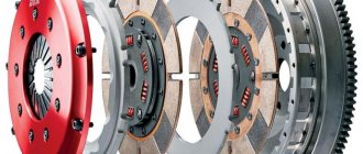
Installation of clutch discs.
Clutch disc hubs have a protrusion in one direction more than in the other. When installed, their large sides should face in different directions. Toward the flywheel
and towards the clutch basket. The first disk is installed with its larger side towards the flywheel. Next comes the intermediate clutch disc.
The second disc is installed with the larger side of the hub facing the basket. If at least one disk is installed incorrectly. They will bump into each other and the basket will not work.
The intermediate disk must move freely in the grooves of the flywheel. This is a very important condition. There should be no jamming or wedging. Otherwise, it will cling to some kind of disk. At least the disk won't be pressed too hard. But it will constantly rotate. And together with it the input shaft rotates. And you won’t be able to shift into gear without the gear crackling. It is better if the intermediate disk is a little free. A characteristic knocking sound when pressing the clutch pedal is heard on all KamAZ vehicles with two clutch discs. And it does not interfere with the clutch.
It happens that the clutch is adjusted correctly. The basket fully depresses the clutch discs. And when starting off, the transmission engages with a big roar. Or it may not be possible to turn it on at all. That's exactly why. That when the basket is depressed, at least one disk constantly rotates along with the flywheel. When the clutch is released, both discs should stop. Only then will the transmission shift into gear without any problems. And the reason for clutch malfunction is the intermediate disc. It jams in the grooves of the flywheel. Touches the disc. And the input shaft continues to rotate when the clutch is depressed. Therefore, it is very important to pay attention to how the intermediate disk is positioned.
After the cart is installed. It is necessary to correctly adjust the position of the clutch basket feet.
Do-it-yourself KAMAZ clutch replacement
To replace the clutch yourself, you will need help removing the gearbox.
Work order:
- Unscrew the fastening nuts, remove the cardan, pneumatic hydraulic booster, and release the starter from the mounting.
- Remove the pipes for the reduction gear, as well as the gear lever.
- Take a jack.
- Place a jack under the engine sump and lift the engine.
- Remove the rear cross member and the spacer rod.
- Release the bracket from the fastening.
- Secure the hoist and tighten it.
- Remove the engine side mounts. Unscrew the gearbox fasteners to the engine.
- Using a hoist, move the gearbox away from the engine until the input shaft comes out, then remove it.
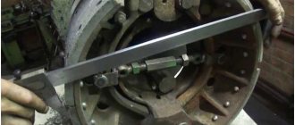
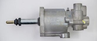
Adjusting the double-disc clutch basket using a caliper
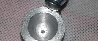
There is a ring on the paws. Adjusting the double-disc clutch of a Kamaz vehicle requires correctly setting the distance from the outer plane of the pressure ring to the clutch disc. The double-disc clutch is adjusted using a caliper. It is necessary to measure from the metal plane of the disk to the outer plane of the pressure ring.
Many people try to do this from the disc hub. But it's not right. And there are no such sizes. The lock washer on each leg is unscrewed. It is closed with a lid that is attached to two bolts at each adjusting nut. Rotating this nut raises or lowers the clutch tab. The gap is set this way. So that the ring is removed from the disk at the same distance. That is, when rotating the adjusting nuts, the disk must be perfectly level.
Factory distance
The factory default distance from the clutch disc to the top plane of the pressure ring is 65 mm. The clutch works perfectly. All operating angles are observed when the clutch fork is pressed onto the release bearing. The clutch operates smoothly. The clutch pedal is adjustable. The clearance on the PSU rod is also easy to set.
Desired distance
Kamaz is used in agriculture. Removing crops from the fields. It is almost impossible to leave the field without setting the clutch on fire. The disc wears out quickly. Therefore, other car models will not appear in the fields for a long time.
When the clutch disc wears out, the paws come out to meet the release bearing. This increases the gap from the disk to the upper plane of the ring. Therefore, when adjusting, it is necessary to take this into account. And make the gap a little smaller. The best option is 62 mm.
At 62mm, the clutch is also highly adjustable. And the difference from 65 mm is almost invisible. But we still have a margin of 3 mm, which will extend the operation of the clutch until the ring rests the release bearing on the gearbox housing. In this case, the clutch will soon stop working.
Undesirable distance
They say on the Internet. That the optimal size is 57 mm is not true. I tried. At the owner's insistence. He failed to immediately prove the opposite. What happened. The clutch released well. But it became impossible to move off without a jerk. The release bearing fork is in the most extreme position. And when the pedal was released, there was a sharp release of the release pedal. The position of the fork when the clutch is depressed should look like this.
And at 57 mm it became like this.
The fork ends up facing the release lever. Smooth release of the release lever became impossible. There are two options left: either wait until the disk is erased. And the paws will come out on their own. But this will most likely damage the gearbox. Or adjust the clutch locally. This is possible although very inconvenient.
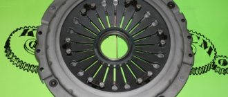
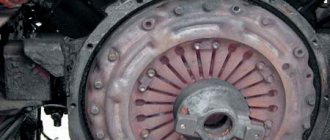
Assembly of parts and their replacement
Installing and replacing a double-disc clutch on a KAMAZ is a simple process. Common types of damage to the driven and pressure discs are cracks on their surfaces, on the linings, wear of the rings and linings, curvature of the disc, deterioration of the hub fastening, damage to the rivets, and scuffing on the disc surfaces. Replacing used gaskets with new ones requires removing old rivets. Disks that have become unusable also need to be replaced.
Not every car owner knows how to properly install clutch discs on a KAMAZ. There is a certain procedure.
The first of the driven disks is installed with the long end of its hub towards the motor, and the second - with the same end towards the gearbox. Before tightening the basket, the discs must be balanced.
As the linings on the driven disks wear out, as well as their replacement, the clutch drive should be adjusted, as well as the free play of the clutch.
Adjusting the Kamaz double-disc clutch without removing the gearbox
The upper hatch of the clutch housing allows you to do this. The stoppers are removed one by one from the adjusting nuts. Then the paws are released. Through the hatch you can see the gap between the ring and the release bearing. The release bearing must be moved away from the basket. The lever on which the PSU rod presses must take a vertical position. In this position, the PSU operates correctly and is easily adjusted. The plane of the release bearing will become clearly visible. After this, the paws are brought in. You can use a wire with a diameter of 3 m. Insert it between the ring and the release ring. When bringing the paws in, the wire should not be pinched too much. It’s not convenient to adjust each foot this way. But much easier than removing the gearbox.
Therefore, if the question arises about how to properly adjust the clutch, I do not recommend setting the gap to 57 mm.
Additional adjustments
The rest of the Kamaz clutch adjustment consists of maintaining the gaps between the release bearing and the pressure ring. It is 1.5 - 3 mm. The gap is adjusted by moving the PSU rod. The lock nut unscrews and the rod rotates. Here it is not necessary to go to the release bearing and measure the clearance on it. It is enough that a slight play appears on the release fork rod. You can hear the release fork hitting the ring. When pressing the fork.
Adjusting the free play of the clutch pedal is to ensure that there is a gap between the rod and the piston in the clutch master cylinder. It is also 1.5 – 3 mm. If the gap is larger, the PSU rod will not fully come out and depress the clutch. If the rod presses on the clutch master cylinder piston. The cylinder will stop working. And the clutch will not be depressed. These are the main points of adjustment on a double-disc clutch.
Source
Adjusting the KAMAZ clutch: instructions
Reliability, excellent performance, efficiency - all this can be said about KAMAZ trucks. The machines are in demand for household, commercial and military purposes. The key to long-term and trouble-free operation is constant checking of the technical condition. Adjusting the KAMAZ clutch is always relevant. This brand is usually equipped with a dry double-disc or single-disc clutch (friction type). During its entire service life, the unit experiences enormous loads. Competent selection of spare parts and timely maintenance will guarantee long-term operation. Adjusting the KAMAZ clutch basket requires experience and certain knowledge.
KAMAZ clutch adjustment technology
Removing and adjusting the KAMAZ clutch is carried out in several steps.
Adjusting the free travel of the KAMAZ clutch pedal
The pedal must have a play of 6 to 12 mm. Measurements are taken from the central part of the plate. The pedal must be lowered until the main cylinder starts working. If there is a deviation from the norm, adjust the distance between the PSU pusher and the stop at the top.
To do this, you will need an eccentric pin connecting the pedal to the top eye of the pushrod. The pedal for traction must press the clutch pedal against the stop from above. The finger is turned so that the gap between the piston and the PSU pusher is in the range from 6 to 12 millimeters. When finished, tighten the castle nut securely. The full pedal travel should be approximately 19 centimeters.
Adjusting the KAMAZ clutch
The manufacturer recommends maintaining a free play value in the range from 3.2 to 4 millimeters. To measure, you will need to move the fork shaft lever by hand. It must move in the direction from the spherical nut of the pusher. It is located on the pneumatic or hydraulic clutch drive amplifier. Adjusting the KAMAZ clutch clearance will require removing the spring: the lever should move no more than five millimeters. If the free play is less than three millimeters, then it is adjusted using a spherical nut. The idle speed of the clutch must be from 3.2 to 4 millimeters.
Adjusting the KAMAZ clutch drive
To measure the function indicator, it is worth pressing the pedal all the way. If the value is less than 24 mm, then complete shutdown will not occur. It is necessary to measure the free play of the pedal and the volume of fluid in the master cylinder. 380 cubic centimeters is the total volume in the hydraulic drive. If the data does not satisfy the requests, it is important to get rid of air in the system. This will return all indicators to normal.
Adjusting the KAMAZ clutch pressure plate
During this operation, you must strictly follow the sequence:
- Initially, the gearbox is dismantled. You can't do it without helpers.
- Remove the clutch basket.
- The clutch discs are dismantled: first the driven one, then the middle one, and finally the driving one.
- New parts are being installed. The order is already reversed.
- It is important to adjust the nickel of the KAMAZ clutch basket.
- The correct installation of all mechanisms is checked in detail.
- The gearbox returns to its place.
If there is only one disc in the clutch design, the job is much easier!
But even a KAMAZ single-plate clutch, adjusting its parts will require serious skills, strength and knowledge. Don't take risks - entrust the matter to professionals. Or do a one-time replacement with a real mechanic. For some mechanics, adjusting the KAMAZ double-disc clutch without removing the gearbox is a reality.
Adjusting the legs of the KAMAZ clutch basket
The case is carried out in several steps:
- The checkpoint is dismantled. Use wrenches to unscrew the fastening bolts.
- Raise the box: it is better to do this with a cargo winch.
- Check the condition of the coupling, tension spring element, and release bearing.
- Unscrew the screws connecting the pressure plate and flywheel. To dismantle the pressure element, the driven disk must be supported.
- Carry out troubleshooting of all parts of the system (preferably).
- Check the condition of the release bearing. A working mechanism rotates easily, without unnecessary sounds.
- Conduct a visual inspection of the working surface of the pressure plate feet. After installing the new parts, the KS feet are adjusted. In this case, you will need a flat slab.
The location of the paws is oriented towards the working position of the pressure plate surface. Important : the operation does not require removing the joint from the additional flywheel. In this work you will need wrenches for the adjusting screws. The KS feet must be positioned so that the distance from the working plane of the pressure plate to the upper edges of the spherical protrusions on the inner surface of the feet is no more than 41 millimeters. But 40 mm is better.
To check the installation of the paws, you will need a special plate. The spherical protrusions must touch the control plate (it is installed on the hub). After completing the adjustment, all screws securing the support plates are tightened until they stop. Assembly proceeds in reverse order.
Source
Design and operation of the clutch drive of the KamAZ-5320 vehicle
Any student work is EXPENSIVE, HIGH QUALITY
100 rub. bonus for the first order. Just 3 questions:
Find out the cost of work
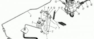
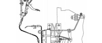
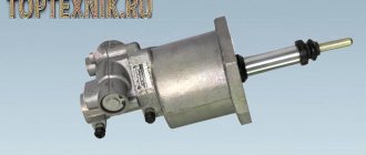
The clutch drive is remote, hydraulic with a pneumatic booster. The inclusion of a pneumatic booster in the drive made it significantly easier for the driver to disengage and hold the clutch in the disengaged state. A schematic diagram of the connection, placement and fastening of control drive elements is shown in Fig. 3.2.
When you press pedal 1 (Fig. 3.2) when the clutch is released, the force from the driver’s foot through the lever and rod is transmitted to the main cylinder 2, from where liquid under pressure through pipelines 10 enters the housing of the follower device 4, which at the same time ensures the passage of compressed air entering through the air line 5 into the cylinder of the pneumatic booster 3. At the same time, liquid under pressure from the main cylinder enters the working hydraulic cylinder 6 of the booster. The follower device, the pneumatic booster cylinder and the working hydraulic cylinder are made in one unit - the pneumohydraulic booster.
| Rice. 3.2. Schematic diagram of the connection and placement of clutch control drive elements of the KamAZ-5320 vehicle: a – schematic diagram of the connection of drive elements; b – placement and fastening of drive elements; 1 – clutch pedal; 2 – main cylinder; 3 – pneumatic booster cylinder; 4 – pneumatic booster tracking device; 5 – air duct; 6 – working hydraulic cylinder; 7 – release clutch with bearing; 8 – lever; 9 – rod; 10 – pipelines and hydraulic hoses. |
The total force, determined by the air pressure in the pneumatic booster cylinder and the fluid pressure in the working cylinder, is transmitted to the rod 9 and through the lever 5, the shaft and the switch fork ensures the movement of the clutch with bearing 7 necessary to disengage the clutch.
Clutch pedal 1 (Fig. 3.2, b) is installed on an axis in a bracket and is equipped with a release spring. The pedal travel is limited by stops in the upper (clutch on) and lower (clutch off) positions. There is an eccentric pin in the connection of the clutch pedal with the rod of master cylinder 2, which allows you to adjust the gap between the pusher and the master cylinder piston when the clutch pedal is released.
The master cylinder (Fig. 3.3) is installed on the clutch pedal bracket. In the housing 1 of the main cylinder there are cylindrical cavities A and compensation cavities B, in which the working fluid is located. The body is closed with a protective cover 2. In the cylindrical cavity A there is a piston 4 with an end sealing collar 5. In the piston 4 there is a hole B, which is closed during the working stroke by a sealing ring located at the end of the rod 3. When the clutch pedal is released, the piston 4 is in the upper position under under the influence of spring 6. From below, the cylindrical cavity A is closed with a plug 7, in the center of which there is a cut hole for connecting the hydraulic drive pipelines.
| When the clutch pedal is released, the cylindrical A and compensation cavities B communicate through hole B, since there is a gap between the end of the rod 3 and the piston 4. When you press the clutch pedal, the rod 3 moves towards the piston 4, closes the hole B and the liquid from the cylindrical cavity A is forced by the piston under pressure through the hydraulic pipelines to the pneumatic-hydraulic amplifier. The pressure of the working fluid is proportional to the force the driver presses the clutch pedal. The pneumohydraulic booster is mounted on the clutch housing (Fig. 3.2) on the right side of the power unit. The amplifier housing (Fig. 3.4) consists of two parts. The front (right in Fig. 3.4) part of the body 14 is made of aluminum alloy, and the rear part 5 is made of cast iron. A gasket is installed between the parts of the housing, which is also the diaphragm 9 of the follower device located above the cylinder of the pneumatic amplifier. The tracking device automatically changes the air pressure on the pneumatic piston 12 depending on the force of pressing the clutch pedal. The main parts of the follower device include a follower piston 7 with a sealing collar, inlet 10 and outlet 11 valves, diaphragm 9 and springs |
| Rice. 3.3. Main cylinder: 1 – body; 2 – protective cover; 3 – rod; 4 – piston; 5 – end sealing collar; 6 – spring; 7 – plug; A – cylindrical cavity; B – compensation cavity; B – hole. |
When the clutch pedal is released (the clutch is engaged), the pneumatic piston 12 and the clutch release piston 4 are in the extreme right (front) position (the pneumatic piston occupies this position under the action of the return spring). The pressure in the cavity in front of the piston corresponds to atmospheric pressure. The position of the clutch release piston 4 is determined by the stop of its pusher in the bottom of the pneumatic piston. In the tracking device, the outlet valve 11 is open and the inlet valve 10 is closed.
When you press the clutch pedal, the working fluid flows under pressure to hole A, creating pressure in the cavity of the clutch release cylinder and at the end of the follower piston 7. Under the pressure of the working fluid, the follower piston acts on the valve device in such a way that the outlet valve 11 closes, and the inlet valve 10 opens, allowing compressed air to pass through pipelines to hole B in the housing of the pneumatic-hydraulic booster. Under the pressure of compressed air, the pneumatic piston 12 moves, acting on the piston rod. As a result, the total force acts on the clutch release piston 2, ensuring complete release of the clutch when the driver presses the pedal with a force of about 200 N (20 kgf).
When the pedal is released, the pressure in front of the follower piston 7 drops, as a result, the inlet valve in the follower device closes and the outlet valve opens. Compressed air from the cavity behind the pneumatic piston is gradually released into the atmosphere, the impact of the piston on the rod is reduced and the clutch is engaged smoothly.
In the absence of compressed air in the pneumatic system, the ability to control the clutch remains, since the clutch can be released using pressure only in the hydraulic part of the amplifier. In this case, the pedal force created by the driver should be about 600 N (60 kgf).
| Rice. 3.4. Pneumohydraulic booster: 1 – spherical nut with locknut; 2 – clutch release piston pusher; 3 – protective cover; 4 – clutch release piston; 5 – rear part of the housing; 6 – combined seal; 7 – follower piston; 8 – bypass valve with cap; 9 – follower diaphragm; 10 – inlet valve; 11 – exhaust valve; 12 – pneumatic piston; 13 – hole plug for draining condensate; 14 – front part of the housing; A – hole for supplying working fluid; B – hole for supplying compressed air. |
students-library.com
Repair of KAMAZ clutch baskets
The clutch of Kamaz-4310, 55111, 43118, 5320 vehicles must be replaced:
— Slipping of the clutch discs as a result of weakening or breaking of the pressure springs, wear of the friction linings of the driven discs, in which it is impossible to restore the free play of the clutch release fork shaft lever by adjustment.
— Incomplete release of the clutch as a result of distortion or warping of the driven and pressure disks, as well as loosening of the rivets of the driven disk hub.
— Mechanical damage to the clutch, interfering with its normal operation.
Removing the clutch of Kamaz-4310, 55111, 43118, 5320 vehicles
— Remove the gearbox, do it without draining the oil from the gearbox housing.
- Screw four technological bolts into the pressure disk until they stop in the casing. Bend the tabs of the lock washers.
— Remove the bolts securing the clutch housing to the flywheel and remove the clutch housing with the pressure plate assembly, the middle and driven clutch discs.
Installation of clutch KamAZ-4310, 55111, 43118, 5320
— Insert the driven and middle disks into the flywheel cavity.
Technical condition - Correct location of the hubs of the driven disks - with short protruding ends towards each other
Align the holes on the clutch housing with the holes in the flywheel.
— Insert the drive shaft of the gearbox into the splined holes of the driven disks KamAZ-4310, 55111, 43118, 5320, insert the casing mounting bolts and tighten them. The tightening torque of the bolts is 53.9–61.8 nm (5.5–6.3 kg/cm). Tighten the bolts evenly in 2-3 steps
Technical specifications - Before installing the Kamaz-4310, 55111, 43118, 5320 clutch housing with the pressure plate assembly, check the correct position of the thrust ring
To check, install and secure the pressure disk assembly on a test stand or on a flywheel with an insert, providing an installation dimension of 29 ± 0.1 mm, and loosen the technological bolts. The correct position of the thrust ring is determined by the mounting size of 54±0.3 mm, the runout of the ends is no more than 0.2 mm.
— Unscrew the technological bolts and remove the spline mandrel
— Install the gearbox.
Fig.1. Clutch disc KamAZ-4310, 55111, 43118, 5320 pressure
1—clutch push disk; 2-ring persistent pull-out levers; 3 — pull lever; 4 — needle roller for tightening the levers and forks of the levers; 5 — axis of the lever fork; 6—thrust ring; 7, 19 — washers; 8 — lever fork; 9 — thrust ring spring; 10 — pull lever with fork and spring assembly; 11 — spring loop; 12 — clutch casing; 13 — adjusting nut of the lever fork; 14 — lock washer; 15 — support plate; 16 — locking plate; 17 - bolt; 18 — coupling bolt; 20—clutch pressure spring; 21 — lining washer; 22 — pressure spring lining
Disassembling the clutch mechanism KamAZ-4310, 55111, 43118, 5320
— Install the clutch housing assembly with the pressure plate on the stand and secure
TRUCKS GAZ, ZIL, KAMAZ, URAL, MAZ, KRAZ
_________________________________________________________________________________________
Adjustments and repairs of clutch KamAZ-5320, 55111
The Kamaz-5320, 55111, 43118 clutch consists of a mechanism and a drive and has the following design features: – the Kamaz-5320 clutch mechanism has a device for automatically setting the middle drive disk to the middle position when the clutch is disengaged. This device does not require adjustment during operation; – the shape of the casing ensures fixation of the pressure springs; – the driven disk has a heat-resistant friction lining with a long service life; – the clutch pedal is suspended, which does not violate the seal of the cabin, and the metal-plastic bushings in the pedal supports do not require replenishment of lubricant. The clutch mechanism Kamaz-55111, 43118, 5320 (Fig. 1) consists of a housing 20, a pressure plate (basket) with a casing 17, pressure springs 16 and pull-out levers 6, two driven disks 1 with friction linings 22 and torsional vibration dampers; middle drive disk 2. The stamped Kamaz-5320 clutch casing is installed on the flywheel using two mounting sleeves 3 and secured with ten M10 and two M8 bolts. The driving disks of the Kamaz-55111, 43118, 5320 clutch 4 and middle 2 have four spikes on the outer surface, which fit into special grooves of the flywheel and transmit engine torque to the friction surfaces of the driven disks, the hubs of which are mounted on the splines of the drive shaft of the gearbox or divider Between the housing 17 of the Kamaz-5320 clutch and the pressure plate 4 there are pressure springs 16, under the action of which the driven and middle drive disks are clamped between the pressure plate and the flywheel. The middle drive disk of the Kamaz-5320 has a lever mechanism 27. It automatically sets disk 2 to the middle position when the clutch is disengaged. The Kamaz-5320 clutch release device consists of 4 pull-off levers balanced on a pressure plate with a thrust ring 14, a clutch release clutch 12 with a thrust bearing 10 mounted on the bearing cover of the drive shaft of the gearbox or divider, and a release fork 13 located on the shaft in the crankcase clutch (divider). The Kamaz-5320 clutch drive (Fig. 2) consists of a clutch pedal 1 with a release spring 11, a master cylinder 2, a compensation tank 5 with working fluid, a pneumohydraulic booster, 18 pipelines and hoses for supplying working fluid from the master cylinder to the clutch booster and air supply from the pneumatic system to the clutch booster.
Fig.1. Clutch KamAZ-43118, 5320, 55111 1 – driven disc; 2 — leading middle disk; 3 — installation sleeve; 4 – pressure disk; 5 — release lever fork; 6 — release lever; 7 – thrust ring spring; 8 — coupling lubrication hose; 9 — spring loop; 10 — release bearing; 11 – release spring; 12 — clutch release; 13 — clutch release fork; 14 - thrust ring; 15 — fork shaft; 16 — external pressure spring; 17 — clutch casing; 18 — heat-insulating washer; 19 — casing mounting bolt; 20 — clutch housing; 21 - flywheel; 22 — friction lining; 23 – internal pressure spring; 24 – input shaft; 25 - torsional vibration damper disk; 26 — internal spring of the torsional vibration damper; 27 — external spring of torsional vibration damper; 8 — driven disk ring; 29 – mechanism for automatically adjusting the position of the middle drive disk. The pneumohydraulic drive booster of the KamAZ-5320 serves to reduce the force on the clutch pedal. It is secured with two bolts to the clutch housing flange (divider) on the right side of the power unit.
Rice. 2. Drive of the clutch mechanism KamAZ-55111, 5320 1 – pedal; 2 – main cylinder; 3.10 – upper and lower stops; 4 – bracket; 5 – compensation tank; 6 – hydraulic pipeline; 7 – lever; 8 – piston pusher; 9 – eccentric pin; 11 – tension spring; 12 – plug; 13 – pipeline; 14 – air release valve; 15 – spherical adjusting nut; 16 – pneumatic piston pusher; 17 – protective cover; 18 – pneumatic hydraulic booster; I – compressed air When you press the Kamaz-5320 clutch pedal, the fluid pressure from the master cylinder is transmitted through pipelines and hoses to the clutch pneumatic booster to the hydraulic piston and to the piston of the follower device, which automatically changes the air pressure in the power pneumatic cylinder of the booster in proportion to the force on the clutch pedal. During operation, as the linings of the driven discs wear out, the clutch drive should be adjusted to ensure free movement of the clutch release clutch. Clutch adjustments KamAZ-43118, 5320, 55111 Clutch adjustments KamAZ-5320, 55111, 43118 during service: - tighten the mounting bolts of the pneumatic booster of the clutch drive: - check by external inspection the tightness of the clutch drive, if necessary, eliminate leaks and bleed the hydraulic system of the drive; — check the action of the release springs of the clutch pedal and the clutch release fork shaft lever, and if necessary, correct the faults; — adjust the clutch drive; — lubricate the clutch release clutch bearing and the clutch release fork shaft bushing; — check the fluid level in the clutch compensation tank and top up if necessary; — drain the condensate from the air-hydraulic booster by unscrewing plug 12 (see Fig. 3). Adjusting the clutch drive of KamAZ-55111, 43118, 5320 consists of checking and adjusting the free play of the clutch pedal, the free play of the clutch release clutch and the full travel of the pneumatic hydraulic booster pusher. Checking and adjusting the free play of the Kamaz-5320 clutch release clutch is carried out by manually moving the fork shaft lever from the adjusting spherical nut 15 of the pusher 16 of the pneumatic hydraulic booster of the clutch drive (in this case, it is necessary to disconnect the spring from the lever). If the free play of the lever, measured at a radius of 90 mm, turns out to be less than 3 mm, then adjust it with the spherical nut of the pneumatic hydraulic booster pusher to a value of 3.7... 4.6 mm, which corresponds to the free play of the clutch release 3.2... 4 mm. Then check the full stroke of the pusher of the Kamaz-5320 pneumatic hydraulic booster by pressing the clutch pedal all the way, while the full stroke of the pusher must be at least 25 mm; with a smaller stroke, complete disengagement of the clutch is not ensured. If the pusher stroke of the Kamaz-5320 pneumatic hydraulic booster is insufficient, check the free play of the clutch pedal, the amount of fluid in the master cylinder (Fig. 3) and the clutch reservoir, and if necessary, bleed the clutch hydraulic system. The free play of the pedal, corresponding to the start of operation of the master cylinder, should be 6 ... 12 mm. It should be measured in the middle part of the clutch pedal area. If the free play is outside the limits specified above, adjust the clearance A between the piston and the master cylinder piston pushrod. Adjust the gap between the piston and the piston pusher of the Kamaz-5320 main cylinder using eccentric pin 9 (see Fig. 3), which connects the upper eye of the pusher 8 with the pedal lever 7. Adjust the gap when the release spring presses the clutch pedal to the upper stop 10. Turn the eccentric pin so that the movement of the pedal from the upper stop until the pusher touches the piston is 6... 12 mm, then tighten and cotter the castle nut. Lubricating the Kamaz-5320 clutch. Lubricate the clutch release fork shaft bushings through two grease nipples 5, and the clutch release clutch bearing through grease nipple 6, making no more than three strokes with a syringe. Otherwise, excess lubricant may get into the clutch housing. Check the fluid level in the compensation tank of the master cylinder visually. The normal liquid level in the tank corresponds to 15...20 mm from the top edge of the tank. The total volume of fluid in the Kamaz-5320 hydraulic clutch is 380 cm3. During service C (autumn), change the fluid in the clutch hydraulic system.
Rice. 3. Pneumatic booster KamAZ-5320 1 - spherical nut: 2 lock nut; 3 — clutch release piston pusher: 4 — protective cover: 5 — clutch release piston; 6 — follower piston body: 7, 21, 24, 26 cuffs; 8 — bypass valve; 9 — breather; 10 membrane of the tracking device; 11 — membrane seat; 12 — plug: 13 — return spring; 14 — air supply cover; 15 — valve stem; 16 — inlet valve; 17 — exhaust valve; 18, 22 — membrane and piston springs; 19 — front body; 20 — pneumatic piston; 23 — piston seal housing; 25 — spacer spring; 27 — rear body; I — brake fluid supply; II - air supply The main cylinder of the Kamaz-5320 clutch consists of a pusher, a housing, a piston, a compensation tank and a tank cover. Repair of the Kamaz-43118, 55111, 5320 clutch. Bleed the hydraulic system of the KamAZ-5320 clutch drive after eliminating the leak in the hydraulic drive in the following order: - Clean the rubber protective cap of the air release valve 14 (see Fig. 3) from dust and dirt, remove it and put the rubber hose supplied with the car onto the valve head. Dip the free end of the hose into brake fluid poured into a clean glass container. — Press the clutch pedal sharply 3...4 times, and then, leaving the pedal pressed, unscrew the air release valve 1/4...1/3 turn. Under the influence of pressure, part of the liquid and the air contained in it in the form of bubbles will come out through the hose. — After the liquid stops coming out, close the air release valve. — Repeat the operations according to paragraphs. 2 and 3 until the release of air from the hose completely stops. During the bleeding process, it is necessary to add brake fluid to the system, not allowing its level in the compensation tank of the master cylinder to decrease by more than 2/3 of normal in order to avoid atmospheric air entering the system. After bleeding is complete, with the clutch pedal pressed, screw the air release valve all the way in and only then remove the hose from its head and put on the protective cap. Next, set the normal fluid level in the master cylinder. The brake fluid that is released from the hydraulic system during pumping can be used again after settling and subsequent filtration. The quality of pumping is determined by the full stroke of the pneumatic hydraulic booster pusher. Check for condensation in the power cylinder of the air-hydraulic booster. To drain the condensate, unscrew the plug in the aluminum housing of the air-hydraulic booster. To drain completely, lightly press the clutch pedal. At least once every three years, it is recommended to flush the clutch drive hydraulic system with industrial alcohol or clean brake fluid, disassemble the master cylinder and pneumatic power steering and refill with fresh brake fluid. Wash the hydraulic system pipelines with alcohol or brake fluid and blow them with compressed air, having first disconnected both ends. Before assembling, moisten the pistons and cuffs of the hydraulic system with brake fluid.
Replace defective (hardened, damaged working edges and worn) cuffs and protective covers. When replacing the pneumatic hydraulic booster of the Kamaz-5320 clutch drive to remove the pneumatic hydraulic booster: - release air from circuit IV of the auxiliary brake system drive and other consumers through the valve on the receiver; — remove the release spring of the clutch release fork shaft lever, disconnect the air piping of the air-hydraulic booster, the hydraulic hose and drain the fluid from the hydraulic drive system; — Unscrew the two bolts securing the pneumatic hydraulic booster and remove the booster with the rod. To install the Kamaz-5320 pneumatic hydraulic booster: - align the mounting holes with the holes in the clutch housing and secure the booster with two bolts and spring washers; — connect the hydraulic hose of the pneumatic power steering and the air pipeline: install the release spring of the clutch release fork shaft. Pour brake fluid into the master cylinder compensation tank and bleed the hydraulic drive system. Check the tightness of the pipeline connections (leaking of brake fluid from the connections is not allowed); if necessary, eliminate the leakage by tightening or replacing individual elements of the connections. Check and, if necessary, adjust the gap between the end of the cover and the travel limiter of the gear divider valve rod. When removing the KamAZ-5320 clutch from the engine after disconnecting the gearbox, first screw four M10x1.25x62 coupling bolts into the pressure plate until it stops in the casing, and then unscrew the bolts securing the clutch casing to the flywheel and remove the casing with the pressure plate assembly, the middle and driven discs clutch. In case of replacing individual parts of the KamAZ-5320 clutch, adjust the position of the thrust ring of the retracting arms before installing it on the engine. To adjust the KamAZ-5320 clutch, install the pressure plate assembly and secure it to the control stand (Fig. 4) or to the flywheel with an insert, ensuring the installation dimension A = (29 + 0.1) mm, and loosen the tightening bolts. The correct position of the thrust ring is determined by the mounting dimension B = (54 + 0.3) mm, the runout of the end T2 relative to T1 should be no more than 0.2 mm. If the position of the thrust ring is violated, adjust the position of the ring on the device using nuts 3, restoring dimension B, while the supporting surfaces of all four pull-off levers must simultaneously touch the thrust ring. Do not adjust the position of the thrust ring using the specified nuts on the engine. Before installing the KamAZ-5320 clutch on the engine, place 15 g of lubricant 158 into the cavity of the front bearing of the drive shaft, located in the crankshaft. Install the Kamaz-5320 clutch using a splined mandrel, ensuring the coaxial arrangement of the axes of the driven disks with the axis of the crankshaft. Pay attention to the correct relative position of the driven disk hubs - with short protruding ends facing each other. The Kamaz-5320 middle drive disk assembly should move easily in the grooves of the flywheel under the action of the pull-out levers. Install the KamAZ-5320 pressure plate (basket) with the casing assembly on the engine flywheel also without additional adjustment, but without distortions, achieving this by uniformly tightening the fastening bolts with a torque of 54... 61.8 Nm (5.5... 6.3 kg/ cm). After the bolts securing the casing to the flywheel are tightened, remove the tightening bolts from the pressure plate. The runout of the thrust ring of the retraction arms relative to the axis of the crankshaft should be no more than 0.5 mm. Rice. 4. Pressure disk (basket) KamAZ-5320 with casing assembly 1 - control stand; 2 - bolt; 3 — adjusting nut; 4 — locking plate; 5 - thrust ring; 6 - coupling bolt: A - installation size; B—installation size; T1, T2 - end runout
_________________________________________________________________________________________
- GAZ-3307 clutch maintenance
- Steering system GAZ-3307
- Gearbox parts for GAZ-3307
- Maintenance of the rear axle GAZ-3307
- Maintenance of the fuel system of the D-245 diesel engine
- Clutch GAZ-3309 with a diesel engine
- Operations for disassembling the GAZ-3309 gearbox
- GAZ-3309 front axle service
- Repair of cardan shafts of GAZ-3309 cars
_________________________________________________________________________________________
_________________________________________________________________________________________
- Operations for assembling basic components of the ZIL-130 engine
- Service and repair operations for the ZIL-130 gearbox
- Maintenance and repair of ZIL-130 clutch
- Repair and adjustment of the rear axle ZIL-130
_________________________________________________________________________________________
- KAMAZ-4310, 43118, 43114
- KAMAZ-5320, 55111, 53212, 5511, 55102
- KAMAZ-65115, 6520, 65117
- KAMAZ-4308
- Engine KAMAZ-740
_________________________________________________________________________________________
- Parts of the cylinder block and head of the YaMZ-236 engine
- Service maintenance of the YaMZ-236 piston group and crankshaft
- Diagnostics and technical adjustments of the YaMZ-236 engine
- Design and adjustment of fuel injection pump and injectors of the YaMZ-236 engine
- Cylinder block and piston YaMZ-238
- Components of the YaMZ-238 diesel fuel supply system
- Design and adjustment of the fuel injection pump of the YaMZ-238 diesel engine
- Technical design of the YaMZ-239 gearbox
_________________________________________________________________________________________
- Components of the front axle and steering rods of the Maz-5516, 5440
- Steering system of Maz-5516, 5440 cars
- Clutch and gearbox parts Maz-5516, 5440
- Maintenance of drive axles of MAZ-5516, 5440 vehicles
- Power steering for Maz-5551, 5335 cars
- Maintenance of cardan transmission of Maz-5551, 5335 cars
- Maintenance and adjustment of clutch MAZ-5551, 5335
- Repair and service of the rear axle of MAZ-5551, 5335 cars
_________________________________________________________________________________________
- Gearbox Ural-4320
- Construction and adjustment of Ural-4320 bridges
- Maintenance of transfer case Ural-4320
- Steering components Ural-4320
_________________________________________________________________________________________
- Servicing the KRAZ-255, 260 gearbox
- Steering mechanism and power steering Kraz-255, 260
- Adjustments and repairs of the power steering cylinder and steering rods of the Kraz car
- Drive axle components and drive shafts Kraz-255, 260
The need for regular maintenance of the unit
To ensure that the mechanism works properly and does not annoy the owner with malfunctions, it is recommended to perform maintenance along with the adjustment work. So, the bolt holding the pneumatic booster should be tightened well. The mechanism is also checked for leaks of working fluid. If a leak is found, it should be repaired.
- Clutch adjustment concept, process instructions, preparation and steps
- VAZ 2106 clutch device replacement of basket and disc adjustment and repair instructions with photos and videos
- How it works, malfunctions and do-it-yourself adjustment of the VAZ 2107 clutch, why it slips, how to adjust, instructions with photos and videos
- Clutch pedal adjustment: how the procedure is performed
Preparing for adjustment
Before properly adjusting and bleeding the clutch on Kamaz 740, 5511 or other trucks, you must perform the following steps:
- Check the tightness of the drive device. To do this, you need to depress the clutch pedal several times. The presence of a serious air leak can be determined by hearing, and a weaker one can be determined by using a soap solution. If brake fluid is leaving the system, this can be determined visually. If problems are detected in the tightness, the components are tightened or the pipes are replaced.
- Carry out diagnostics of the fluid level in the expansion tank of the drive device. The volume of consumables should be about 15-20 mm below the edge of the tank neck. If required, the fluid level is replenished. It is not recommended to mix supplies from different manufacturers when performing this task.
- Check the operation of the pedal release springs, as well as the system release fork pulley lever.
- Tighten the bolts that secure the pneumatic reinforcement device CC. This procedure is performed using a torque wrench. The tightening torque should be about 90-100 Nm.
- Drain condensate, if any, from the pneumatic hydraulic booster.
Adjusting the clutch operation
To complete the task, you will need a special homemade product in the form of a piece of wire, one side of which should be 2 mm and bent at an angle of 90 degrees. The thickness of the rod is at least 3-4 mm. This size is optimal for controlling the gap between the tab outline and the disc release component. Adjustment is made using the nut of the pneumatic booster device. The legs must be brought to the ring through a hole located in the upper part of the crankcase.
You need to adjust the clutch like this:
- The locking screws are unscrewed with a wrench.
- The stoppers and plates are dismantled.
- Each nut is loosened and released 5 turns; for convenience, it is recommended to use a ratchet. If the penny protrudes beyond the surface of the ring, it must be recessed, checking in advance for the presence of ferodo at the bottom.
- When performing this task, you can also change the spring elements if they are worn out. The paws should be positioned so that they are in equal contact with the ring.
- The disk area runout is checked. If necessary, the bearing device is lubricated. The adjustment gap should be about 29-30 mm.
How to adjust the pedal free play?
To adjust the gap, unscrew and loosen the castle nut of the eccentric pin (see Fig. Adjusting the gap) and, by rotating the eccentric pin, set the required free play of the clutch pedal.
remove plug 5 from the tank and fill the tank with working fluid to a level not lower than 15-20 mm from the top cap of the tank filler neck;
remove the cap from the bypass valve (see Fig. Bleeding the clutch), place a hose on the valve head, the free end of which is lowered into a transparent vessel with working fluid;
unscrew the bypass valve ½-1 turn and sharply press the clutch pedal all the way to the pedal stop until air bubbles stop emitting from the working fluid;
during pumping, add working fluid to the system, not allowing its level in the tank to drop below 40 mm from the upper edge of the filler neck;
at the end of pumping, with the pedal pressed all the way, screw the bypass valve all the way, remove the hose from the valve head, and put on the cap;
After bleeding the system, add fresh working fluid to the tank to the normal level.
The quality of pumping can be determined by the full stroke of the clutch pneumatic booster pusher (see Fig. Bleeding the clutch). If the fluid level in the master cylinder is normal and there is no air in the fluid, then the full stroke of the pusher should be at least 25 mm. To measure the full stroke of the pusher, press the clutch pedal all the way.