Interpretation of GAZelle Next instrument cluster icons.
Location of alarms.
1. Indicator light (orange) for particulate filter clogging .
Informs the driver about the status of the particulate filter.
2. Warning lamp (orange) high exhaust temperature.
Informs the driver that the particulate filter is clogged.
3. Warning light (orange) for low coolant level.
When the warning light comes on, it is necessary to eliminate the cause of the coolant leak and bring the level in the expansion tank of the engine cooling system to normal.
4. Indicator (red) of critical engine malfunction.
Lights up briefly when the instruments (ignition) are turned on. If there are no malfunctions, it lights up when the devices (ignition) are turned on and lights continuously for 2-5 seconds, then goes out.
When lit continuously, it informs the driver about the presence of a critical malfunction (engine overheating, drop in oil pressure, gas pedal failure, critical malfunction of the electronic unit) in which case it is necessary to immediately stop driving and stop the engine.
5. MIL indicator (orange).
Lights up briefly when the instruments (ignition) are turned on. Informs the driver about malfunctions recorded by the on-board diagnostic system related to exhaust gas and particulate emissions.
If the indicator lights up continuously, it is necessary to diagnose the engine control system at a maintenance facility.
After the malfunction is eliminated, the indicator remains on for four engine starting cycles, then goes out.
6. Indicator (orange) “Attention” of the engine control system.
If the control system is working properly, the indicator lights up after turning on the devices (ignition) and lights continuously for 2-5 seconds, then goes out. This indicates that the system is ready to start the engine.
When lit continuously, it informs the driver about the presence of a non-critical fault, in which case the driver can continue driving. In this case, the vehicle needs to be diagnosed at a maintenance facility.
7. Signal lamp (green) for turning on the left direction indicators.
8. Indicator (white) for turning on daytime running lights.
9. Alarm (red) for abnormally high coolant temperature.
Lights up briefly when the instruments (ignition) are turned on. If the indicator lights up continuously, you must immediately stop the engine to determine and eliminate the cause of overheating.
10. Signal lamp (green) for turning on the side lights.
11. Signal indicator (red) “STOP”.
Lights up simultaneously with one of the red hazard warning lights. When these warning lights come on, further operation of the vehicle is not allowed until the malfunction is eliminated.
Lighting of the indicator in a flashing mode and duplication of a periodic sound signal indicates a request for a stop by passengers (pressing a button in the cabin).
12. Indicator (blue) for turning on the high beam headlights.
13. Indicator (orange) of the minimum fuel reserve in the tank.
Lights up when the fuel level float is in the region of 8 liters.
14. Indicator (green) for low beam headlights.
15. Signal lamp (green) for turning on the right direction indicators.
16. Indicator (orange) for turning on the center differential lock or reserve.
17. Signal indicator (orange) for front axle differential lock activation or reserve.
18. Alarm (red) for unfastened seat belts or reserve.
19. Warning lamp (red) for airbag or seat belt malfunction or backup.
20.
21. Indicator (orange) for disabling the exchange rate stabilization system or reserve.
22. Warning lamp (red) for malfunction of the electronic brake force regulator or reserve.
Lights up when the instruments (ignition) are turned on and goes out after a few seconds.
Continuous lighting of the indicator or if it lights up while driving indicates a malfunction of the brake force regulator.
The vehicle must be checked by a service facility. Operating the vehicle until this malfunction is eliminated is not allowed.
23. Indicator (orange) of a malfunction of the exchange rate stabilization system or reserve.
Lights up when the instruments (ignition) are turned on and goes out after a few seconds.
Continuous lighting of the indicator or its lighting up while driving indicates a malfunction of the exchange rate control system.
The vehicle must be checked by a service facility.
24. Signal indicator (green) for downshift or reserve.
25. Warning lamp (orange) for anti-lock brake system malfunction or backup.
Lights up when the instruments (ignition) are turned on and goes out after a few seconds.
If the warning light stays on for a long time or comes on while driving, it indicates a malfunction of the anti-lock brake system. At the same time, the service brake system remains operational.
The vehicle must be checked by a service facility.
26. Alarm (red) for open doors and/or extended running boards.
Illumination of the indicator in a flashing mode and duplication of a periodic sound signal when driving indicates unlocked front and/or side doors and/or an extended running board.
If the indicator lights up continuously and is accompanied by a constant sound signal, it indicates that the rear doors of the bus are not closed.
27. Indicator (orange) for rear axle differential lock activation or reserve.
28. Indicator (orange) for turning on the air heater (for a diesel engine).
Lights up when the devices are turned on. Start the engine with the starter only after the warning light goes out.
29. Indicator (orange) for the presence of water in the fuel (for a diesel engine).
Lights up briefly when the devices are turned on.
Continuous lighting of the indicator indicates the presence of water in the fuel filter. Stop the engine immediately, drain the fuel filter, or contact a service center.
30. Low battery indicator (red).
Lights up when the instruments (ignition) are turned on and goes out after the engine is started.
If the indicator lights up when the engine is running, it indicates a weak tension or break in the drive belt of the engine's attachments or a malfunction in the battery charging circuit.
31. Signal lamp (red) for engaging the parking brake.
Lights up with a flashing light when the instruments (ignition) are turned on, if the car is slowed down by the parking brake (duplicated by a short-term sound signal when the car is moving).
32. Alarm (red) for emergency low oil pressure.
Lights up when the instruments (ignition) are turned on and goes out after the engine is started (duplicated by a short-term sound signal when the car is moving).
If the warning light comes on while the engine is running, it indicates low oil pressure in the engine lubrication system; in this case, you must immediately stop the engine and check the oil level in the crankcase, top up if necessary. If the oil level is within normal limits, contact a service center.
33. Alarm (red) for emergency low level of brake fluid in the brake master cylinder reservoir.
If the warning light comes on, this indicates a malfunction of the brake system.
The vehicle must be checked immediately by a service facility.
Operating the vehicle until this malfunction is eliminated is not allowed.
34. Indicator (orange) for turning on the rear fog light.
ATTENTION!
It is prohibited to operate a vehicle with red warning lights constantly on or flashing. If it is impossible to eliminate the malfunction on site, the vehicle may be driven to a maintenance facility, except in cases where the warning lights come on, prohibiting further operation. If you fail to contact a maintenance facility in a timely manner, the vehicle may be removed from warranty service. The operating time of the vehicle with the warning lights on is recorded in the memory of the control unit.
I was getting ready for a 400 km trip to Tula. At 5 am I left, picked up a colleague, while I was waiting for him, I went out to clean the windshield wipers. The engine stalled. I'm starting again. The water in fuel sensor came on. I went to a gas station, filled up with anti-gel and 56 liters of fuel. It's -13° outside. Well, I think it'll blow up in a minute. I just leave the city, the car doesn’t pull, it’s fine at idle, but it stalls under load. The check light came on, the check with an exclamation mark to boot. I drained the fuel from the separator, pumped it, and started it up. Looks like she's gone. I decided to drive through the city to the exit to the highway from another region, and decide whether the car would go to Tulu or not. I drove fine, the check went out. As soon as I got on the highway, it was the same story again. 20 km per hour in second gear, full throttle to the house. It took a long time to sort all the things, the tools, into the passenger savior, because... it was difficult to climb... the snow was still knee-deep and not ending. I went to Tula and Moscow at the same time. I bought an original fuel filter and changed it. The car drove off, but it was terribly slow. I drove around the city in circles for 3 hours. The next day everything is sad again. Went in for diagnostics. Lots of errors on fuel, pressure... one error on the camshaft and the last one. I got to work. It started up there, didn't drive, now it starts and stalls. Through the miracle of the Gas Assistance program, on February 1st in the morning, he will travel from Kursk to Belgorod to the official dealer on a tow truck at the expense of the manufacturer, I will post the news below) News from the fields) They asked me to sit for 4 hours. They called. Let's go for a ride with the receptionist. We drove 10 kilometers around the city - the flight was normal. I ask what happened. They say that I didn’t click the connector on the filter, although I double-checked it... Well, okay, I picked up the docks at the reception, and off I went.
Scheduled Maintenance
Regular maintenance is the key to vehicle efficiency, reliability and safety.
It must be remembered that the responsibility for maintaining the vehicle in a reliable, serviceable condition rests entirely with its owner. The work performed during maintenance is indicated in the service book attached to the vehicle. Carry out maintenance at a service station.
Safety precautions during maintenance:
It is necessary to turn off the instruments and the starter and remove the key unless otherwise required during maintenance. Hands, tools and clothing should not be in the area of drive belts or pulleys while the engine is running. The radiator cooling fan may turn on at any time
Keep hands and clothing away from the fan blades. Take precautions when working on a hot engine. It is not allowed to touch wires and electrical equipment when the devices and starter are turned on. Do not leave the engine running in an unventilated area. If possible, work in the engine compartment with the engine off and the negative terminal of the battery disconnected. If it is necessary to carry out work in the engine compartment while the engine is running, it is necessary to place the car on a solid and level horizontal platform and brake the car with the parking brake. Do not work under a vehicle supported only by a jack.
For safety, you should put chocks under the wheels. Sparks and open flames are not allowed near the battery and fuel system parts. No smoking. Many operating fluids used in cars are toxic. It is unacceptable for them to come into contact with the skin or eyes. If necessary, protective gloves should be worn. Follow label and container directions. You must protect your eyes when working under a vehicle. Prolonged contact with engine oil may cause skin irritation. Hands should be washed thoroughly after contact.
Types of maintenance
The following types of maintenance are established:
- Daily Maintenance (DM).
- Periodic maintenance (MOT).
- Seasonal maintenance (MS).
Seasonal maintenance is performed once a year, together with regular maintenance.
The frequency of maintenance is determined depending on the operating conditions of the vehicle.
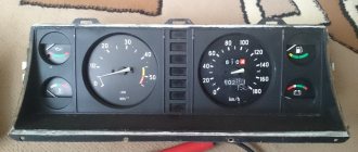
GAZelle Business dashboard: description of icons
The dashboard of a car with a UMZ 4216 engine has 26 current status indicators. Lamps and devices are divided into three groups:
- notifying;
- indicator;
- warning.
The third on the list is a type of signal that is reflected in red and requires immediate intervention from the motorist. Serious breakdowns or problems with the machine are displayed here.
The photo shows the location of all elements of the 2016 Gazelle Business tidy.
Important! In versions 2010, 2012 and 2022, the location of the indicators and the design of the tidy itself may differ.
A complete decoding of combinations and decoding of icons describes the appearance and functional decoding.
- 1 – Fuel tank full indicator. The pointer element is based on a mechanical principle and rarely fails.
- 2 – Speedometer. The electronic part has a gradation of 20 km/h from 0 to 200.
- 3 – Handbrake operating position indicator. If the handbrake is raised, the element lights up red. The serviceability of the line is checked when the ignition is turned on - the lamp flickers. If the car starts moving, the indicator is duplicated by an additional sound signal.
- 4 – Battery health indicator. If the lamp ignites, there are problems with charging or the integrity of the battery is compromised. You need to check the generator wires and measure the voltage at the output terminals.
- 5/9 – turn signal indicators. It also indicates that the hazard warning system is activated. When switched on, they blink green.
- 6 – emergency oil pressure indicator. When the ignition is turned on, the light comes on - this indicates that the electrical line is working properly. When the engine reaches idle speed, the lamp goes out, which indicates that the required pressure has been built up. In some cases, the indicator begins to blink during a critical decrease in the crankshaft speed. When you let it go, everything becomes normal.
- 7 – STOP is located strictly in the center of the instrument and lights up simultaneously with some elements. The combination indicates that further use of the vehicle is strictly prohibited until the breakdown is repaired. A failure can be identified by the icon lighting up at the same time.
- 8 – ECM unit status indicator. The warning light is activated immediately after the ignition is turned on and does not go out for 7-8 seconds. If the sequence is followed, this indicates that the module is ready to start the engine. If the indicator periodically flashes while driving, one of the circuit elements has failed or there is an error in the electronic engine control system.
- 10 – indicator of the anti-lock brake system. When it is activated, the operation of the mechanism is disrupted. You can find out about the presence of a module in the vehicle's service manual.
- 11 – standard tachometer. The magnetic circuit is lined from 0 to 6 and indicates the actual speed of the crankshaft.
- 12 – the EBD option is installed on some vehicle modifications. Usually mounted in tandem with an ABS device. The indicator is displayed in the upper right corner. The ebd light says that the brakes are not working properly, the electronic force distribution is broken - requires immediate repair. If you continue to drive the car, the calipers may not work properly.
- 13 – indicator that the doors are closed correctly. If the car is moving with the locks open, the icon lights up and sounds a sound signal.
- 14 – the lamp is installed on a Cummins engine with a 4x4 drive and is responsible for indicating that the transfer clutch is engaged. Not used on vehicles version 3302 and similar.
- 15 – critical overheating lamp of the power unit. If an element is displayed on the dashboard, you need to stop immediately and turn off the engine. Continued use of the car until the antifreeze cools down is fraught with irreversible consequences for the car. In some situations, pipes rupture and the piston group jams.
- 16 – pointer indicator of the actual engine coolant temperature. Driving is allowed until the pointer moves into the red zone. The normal position is approximately in the middle of the scale in the green compartment.
- 17 – service key “mode” – installed on all modifications of cars.
- 18/22 – the light indicates that the rear/front fog lights are on. When the lighting is turned off, the indicator goes out.
- 19 – the indicator is intended to notify the driver about the inclusion of the high-range head lighting mode.
- 20 – indicator for turning on the headlights, located in the central part of the LCD display, paralleled by an audible alarm.
- 21 – indicator for turning on the low beam headlights.
- 23 – emergency loss of brake fluid volume in the expansion tank. When the indicator turns on, you must immediately stop and check the serviceability of the lines, eliminate leaks and replenish the tank.
- 24 – odometer. The lower part indicates the daily mileage, the upper part indicates the total mileage.
- 25 – reset key – using the control, the accumulated kilometers per day are reset to zero.
- 26 – fuel tank reserve lamp, lights up when most of the fuel is used up. The indicator lights up when there is no more than 8 liters of gasoline left in the fuel tank. It is prohibited to move in this mode for a long time - this may damage the pressure pump.
Opening and closing the hood
Opening
Pull handle 1 of the hood lock, located on the left under the instrument panel.
Lift the front of the hood slightly by sliding the safety latch 2 upward and lift the hood.
Fold out the support stand and insert the stand into the hood hole.
Closing
Lift the front of the hood, release, stow and secure the support post.
Lower the hood to a distance of 100–150 mm from the engine compartment.
Release the hood until it closes.
Make sure by trying to lift the hood that it is securely locked.
ATTENTION!
Before closing the hood, make sure there are no foreign objects in the engine compartment.
Scheduled Maintenance
Regular maintenance is the key to the efficiency, reliability and safety of the bus. It must be remembered that the responsibility for maintaining the bus in a reliable, serviceable condition rests entirely with its owner.
The work performed during maintenance is indicated in the service book attached to the bus. Carry out maintenance at a service station.
Safety precautions during maintenance:
It is necessary to turn off the instruments and the starter and remove the key unless otherwise required during maintenance. Hands, tools and clothing should not be in the area of drive belts or pulleys while the engine is running. The radiator fan may turn on at any time
Keep hands and clothing away from the fan blade area. Take precautions when working on a hot engine. It is not allowed to touch wires and electrical equipment when the devices and starter are turned on. Do not leave the engine running in an unventilated area. If possible, work in the engine compartment with the engine off and the negative terminals of the battery disconnected. If it is necessary to carry out work in the engine compartment while the engine is running, it is necessary to place the bus on a solid and level horizontal platform and brake the bus with the parking brake. You cannot work under a bus supported only by a jack.
For safety, you should put chocks under the wheels. Sparks and open flames are not allowed near the battery and fuel system parts. No smoking. Many operating fluids used in buses are toxic. It is unacceptable for them to come into contact with the skin or eyes. If necessary, protective gloves should be worn. Follow label and container directions. You must protect your eyes when working under a bus. Prolonged contact with engine oil may cause skin irritation. Hands should be washed thoroughly after contact.
Types of maintenance
The following types of maintenance are established:
- Daily Maintenance (DM).
- Periodic maintenance (MOT).
- Seasonal maintenance (MS).
Seasonal maintenance is performed once a year, together with regular maintenance.
The frequency of maintenance is determined depending on the operating conditions of the bus.
Seat belts
Seat belts are an effective means of protecting the driver and passengers from the serious consequences of road accidents.
Cars can be equipped with two types of belts: three-point (diagonal-waist) with inertial reels, two-point (waist) with automatic reels, or static with manual adjustment of the belt length. In the first case, the belts do not need adjustment. In the second case, individual adjustment of the belt length is necessary; the waist strap should fit snugly to the hips. The length of the strap is changed using a regulator.
The seat belts of the driver and front right passenger are equipped with mechanisms that allow you to adjust the upper guide of the seat belt in height, thereby ensuring ease of use of the belt for people of different height groups.
To adjust the position of the top guide, pull button 1 towards you and at the same time move it either up or down as necessary.
For fastening with a belt
slowly (without jerking) pull the belt strap by tongue 1 so that its length along the chest and hips is approximately the same, and insert it into the lock 2 corresponding to the seat until a characteristic click is heard.
The top of the belt should pass through the middle of the shoulder and never over the neck or under the arm, and should fit snugly around the upper torso.
The lap part of the belt should lie as low as possible and always fit snugly against the hips. Otherwise, you should release the belt and pull it.
To release the belts
press the red button 3 of the corresponding lock. In this case, the tongue will be pushed out of its socket by the spring. Pull the belt strap back by the tongue with your hand to make it easier for the mechanism to wind it up.
Pregnant women must also wear seat belts. It must be remembered that the belt should be positioned in such a way as to avoid any pressure on the abdomen. The waist part of the belt should be located below the stomach.
ATTENTION!
Belts that have experienced heavy loads in a traffic accident or that have abrasions, tears or other damage must be replaced with appropriate new seat belt assemblies.
Any changes in the design of seat belts are unacceptable. It is forbidden for two people to fasten themselves with the same seat belt; it is especially unacceptable to fasten a child sitting on a passenger’s lap with a belt.
Links
| This is a preliminary article about cars. You can help the project by adding to it. |
| Trucks, buses and all-terrain vehicles of the Gorky Automobile Plant | |
| GAZ trucks |
|
| GAZ buses |
|
| GAZ special equipment |
|
Economical driving
Bus driving style is the most important factor affecting fuel consumption.
— Maintain a sufficient distance from the vehicle in front to allow you to move more smoothly in traffic. Avoid sudden acceleration and frequent braking.
— As the speed increases, the resistance to the movement of the bus increases, and therefore fuel consumption increases. In addition, as the speed of the bus increases, the wear rate of the tires increases. — For economical driving mode, it is recommended to select a gear in the crankshaft speed range from 1600 to 2400 min-1, which corresponds to the green zone of the tachometer.
Driving under load in higher gears with a low crankshaft speed leads to increased fuel consumption, increased noise in the transmission and more intensive wear of engine parts.
Incorrect use of lower gears with increased crankshaft speed, sudden acceleration and driving at high speeds also lead to increased fuel consumption.
The general condition of the bus and the serviceability of its systems largely determine fuel consumption.
— Maintain the bus in technically sound condition at all times. The values of the adjustable parameters must comply with the manufacturer's requirements.
— Check the air pressure in your tires regularly. Insufficient pressure increases rolling resistance. This leads to increased fuel consumption, increased tire wear and a negative impact on the behavior of the bus on the road.
Increased tire pressure beyond normal limits negatively affects the smooth running of the bus.
The activation of the engine management system malfunction indicator while driving indicates that the engine is operating in standby mode, accompanied by increased fuel consumption.
The characteristics and operating conditions of the bus have a significant impact on fuel consumption.
— Insufficiently heated oil in the engine and transmission units leads to increased resistance and wear of rubbing surfaces. For faster warm-up, we recommend starting to drive at moderate engine speeds without sudden acceleration one to two minutes after starting a cold engine. At low ambient temperatures and after a long period of parking, it is recommended to drive for some time in lower gears with a low engine speed.
Use only lubricants recommended by the manufacturer. The temperature range of the oil used in the engine lubrication system must correspond to the stable ambient temperature range.
— Avoid driving short distances where you have to stop the engine and then start it again. This prevents the engine from reaching normal operating temperature. — Avoid running the engine unnecessarily while parked. — Avoid carrying unnecessary items and cargo on the bus.
Reporting a malfunction
The battery icon lights up if the voltage in the on-board network drops; often this problem is associated with a lack of battery charge from the generator, so it can also be called the “alternator icon”. On vehicles with a hybrid engine, this indicator is supplemented by the inscription “MAIN” at the bottom.
The oil icon , also known as a red oil can, indicates a drop in the oil level in the car engine. This icon lights up when you start the engine, and does not go out after a few seconds or may light up while driving. This fact indicates problems in the lubrication system or a drop in oil level or pressure. The oil icon on the panel may have a droplet or waves at the bottom; on some cars the indicator is supplemented with the inscription min, senso, oil level (yellow inscriptions) or simply the letters L and H (characterizing low and high oil levels).
The airbag icon can light up in several ways: either the red inscription SRS and AIRBAG, or “a red man wearing a seat belt,” with a circle in front of him. When one of these airbag icons lights up on the panel, the on-board computer notifies you of a malfunction in the passive safety system, and in the event of an accident, the airbags will not deploy. Read the article on the website for the reasons why the airbag sign lights up and how to fix the problem.
The exclamation mark icon may look different and its meaning will accordingly be different. So, for example, when the red (!) light is on in the circle, this indicates a malfunction of the brake system and it is advisable not to continue driving until the cause of its occurrence is determined. They can be very different: the handbrake is up, the brake pads are worn out, or the brake fluid level has dropped. A low level is precisely what poses a danger, because the reason may not only be in heavily worn pads, as a result of which, when you press the pedal, the fluid disperses throughout the system, and the float gives a signal about a low level, the brake hose may be damaged somewhere, and this is much more serious. Although, very often the exclamation mark lights up if the float (level sensor) is faulty or shorted, and then it simply lies. On some cars, the exclamation mark is accompanied by the words “BRAKE”, but this does not change the essence of the problem.
An exclamation mark can also light up in the form of an “attention” sign, both on a red and yellow background. When the yellow “attention” sign lights up, it informs about a malfunction in the electronic stabilization system, and if it is on a red background, it simply warns the driver about something, and, as a rule, explanatory text is displayed on the dashboard display or combined with other informative text designation.
The ABS icon may have several display options on the dashboard, but regardless of this, it means the same thing on all cars - a problem has occurred in the ABS system, and that the anti-lock wheel system is not working at the moment. You can find out the reasons why ABS does not work in our article. In this case, movement can be made, but there is no need to rely on the ABS to activate; the brakes will operate as usual.
The ESP icon may either light up intermittently or stay on constantly. A light with this inscription indicates problems with the stabilization system. The Electronic Stability Program indicator, as a rule, lights up for one of two reasons - either the rotation angle sensor has failed, or the brake light sensor (aka “frog”) has died for a long time. Although, there can be a more serious problem, for example, the brake system pressure sensor is covered.
The engine icon , some drivers may call it the “injector icon” or check, may glow yellow when the engine is running. It informs about the presence of engine errors and malfunctions of its electronic systems. To determine the reason for its appearance on the dashboard display, self-diagnosis or computer diagnostics are performed.
The glow plug icon may light up on the dashboard of a diesel car; the meaning of such an indicator is exactly the same as the “check” icon on gasoline cars. When there are no errors in the electronic unit’s memory, the spiral icon should go out after the engine warms up and the glow plugs are turned off. Read how to check glow plugs here.
Gazelle Next
Gazelle Next is a car that has been almost completely changed compared to the previous model. Body, interior, engine, steering, independent suspension - these are just the main changes. The car has become safer, more comfortable, more manageable, and more economical. Due to such deep modernization, the car has become more complex. This means that servicing it requires much higher qualifications. Our company has many years of experience (since the next gazelles appeared on the roads) in repairing cars of this make and model. And now a little more about the changes.
Body
Compared to the previous model, it has undergone significant changes. The frame has been strengthened, the metal parts of the body are now galvanized, which means that in the future there will be significantly fewer problems with corrosion. Inside, the driver will have electric windows, an adjustable seat, and heated mirrors. As the number of electricians increases, more problems will inevitably arise with their repair.
Engine
The new diesel engine for the gazelle next is the Cummins ISF. It is more powerful and economical than the engines of previous models. Owners speak of it as a reliable engine with good dynamics. However, even such an engine can develop problems over time. Engine repairs must be carried out in station conditions. Repairs should be carried out by professionals. Grad Auto has all the necessary equipment and personnel to perform repairs of any complexity: from replacing a valve cover to a complete engine overhaul.
Suspension, brakes, steering
The suspension, brakes and steering of the gazelle next have undergone significant changes. Towing and anti-skid systems were added to the car, providing more effective braking and safety. The suspension of the new gazelle is independent, spring. It is more comfortable, but not as reliable as the old spring one. The steering has become rack and pinion, which has dramatically improved handling.
Contact our service and be confident in the quality of repairs for your gazelle. We provide a guarantee for all work.
GET TO KNOW US! VISIT OUR GROUP
https://vk.com/albums-28701088
Bus movement
It is recommended to start driving the bus with a partially warmed up engine. If this is not possible, and the engine is warmed up while the bus is moving, then at low ambient temperatures and after a long stay, it is recommended to move for some time in lower gears with a low engine speed. As it warms up, gradually shift to higher gears.
When overcoming a ford, make sure that its depth, taking into account the oncoming wave and the water shaft in front of the bus, does not exceed the height of the lower edge of the front buffer above the road surface; in this case, you must move at the minimum possible speed, not exceeding 20 km/h, in order to avoid water being thrown into the air intake air filter.
After overcoming a ford, after washing the bus, as well as when driving for a long time on a wet road, when water gets into the brake mechanisms of the wheels, it is necessary to perform several smooth braking while driving to dry the discs, drums and brake linings.
When driving through puddles, reduce your speed to avoid hydroplaning, which can cause skidding or loss of control; With worn tires this danger increases.
If possible, drive the bus without sudden acceleration and deceleration, as this leads to increased tire wear and increased fuel consumption.
Driving a bus in 3rd, 4th and 5th gears at low engine speeds (up to 1500 rpm) leads to additional loads on the engine and transmission and may be accompanied by the appearance of resonance phenomena in the transmission. Driving in these modes is not recommended. To avoid such phenomena, you should switch to a lower gear.
To avoid damage to the plastic housing of the clutch master cylinder, it is prohibited to operate the clutch pedal in the direction opposite to its normal movement to disengage the clutch when the bus rod is connected to the clutch pedal.
To ensure long-lasting operation of the gearbox when operating the bus, be sure to follow the following rules, which will ensure easy and silent gear shifting:
1. The clutch drive must ensure complete disengagement of the clutch. When the pedal is depressed, the clutch should not “drive”.
2. All gear changes should be carried out by smoothly moving the lever only after the clutch is completely disengaged. Shifting gears too quickly leads to premature wear of the synchronizers or their failure. It is not allowed to change gears with the clutch not completely disengaged, as well as to simultaneously operate the pedal and lever.
3. It is not allowed to engage the clutch when the gear is not disengaged.
4. Engage the rear entry gear only after the bus has come to a complete stop.
The driving axle of the bus is equipped with a bevel gear differential, which allows the bus wheels to rotate at different speeds, which is necessary to ensure stability and controllability when the bus is moving. Long-term (more than 5 minutes) slipping of one of the wheels of the drive axle can lead to overheating of the differential parts and its failure. If such a situation arises, use available means to improve wheel grip on the road or evacuate the bus from a dangerous area in tow.
GAZ errors via OBDII protocol
Fuel system and air supply
P0000-P0099, P0100-P0199, P0200-P0299
P0016 - Temporary inconsistency (phase shift) of the camshaft and crankshaft
P0031 - Oxygen sensor heater circuit short circuit
P0032 - Open circuit of the oxygen sensor heater
P0068 - Throttle position sensor error (mismatch with absolute pressure sensor)
P0071 - Ambient temperature sensor error (mismatch with other sensors)
P0072 - Ambient temperature sensor circuit short circuit
P0073 - Ambient temperature sensor circuit open
P0101 - Mass air flow sensor signal out of acceptable range
P0102 - Mass Air Flow Sensor Circuit Low
P0103 - Mass Air Flow Sensor Circuit High
P0106 - Absolute pressure sensor signal out of acceptable range
P0107 - Intake Air Absolute Pressure Sensor Circuit Low
P0108 - Intake Air Absolute Pressure Sensor Circuit High
P0112 - Air Temperature Sensor Circuit Low
P0113 - Air Temperature Sensor Circuit High
P0116 - Coolant temperature sensor signal out of acceptable range
P0117 - Coolant Temperature Sensor Circuit Low
P0118 - Coolant Temperature Sensor Circuit High
P0121 - Throttle position sensor signal out of range
P0122 - Throttle Position Sensor Circuit Low
P0123 - Throttle Position Sensor Circuit High
P0125 - Insufficient Cooling Temperature for Fuel Control Feedback
P0128 - Thermostat malfunction
P0129 - Incorrect reading of the absolute pressure sensor when the ignition is turned off
P0130 - Oxygen sensor No. 1 circuit faulty
P0131 - Low signal level of oxygen sensor No. 1, to the converter
P0132 - High signal level of oxygen sensor No. 1, to the converter
P0133 - Slow response to rich or lean oxygen sensor No. 1
P0134 - Open circuit of oxygen sensor No. 1
P0135 - No. 1 Oxygen Sensor Heater Malfunction
P0136 - No. 2 Oxygen Sensor Circuit Malfunction
P0137 - Low signal level of oxygen sensor No. 2 (after the converter)
P0138 - High signal level of oxygen sensor No. 2 (after the converter)
P0140 - Oxygen sensor signal circuit open No. 2
P0141 - No. 2 Oxygen Sensor Heater Malfunction
P0155 - No messages on the data bus
P0171 - Fuel system too lean
P0172 - Fuel system too rich
P0200 - Injector control circuit faulty
P0201 - Injector 1 control circuit open
P0202 - Injector 2 control circuit open
P0203 - Injector 3 control circuit open
P0204 - Injector 4 control circuit open
P0217 - Engine cooling system overheating
P0219 - Exceeding the permissible engine speed
P0222 - No. 2 Throttle Position Sensor Circuit Low
P0223 - No. 2 Throttle Position Sensor Circuit High
P0230 - Fuel pump relay control circuit malfunction
P0261 - Injector 1 control circuit short to ground
P0262 - Short circuit to power supply or open circuit of injector 1
P0263 - Injector 1 driver faulty
P0264 - Injector 2 control circuit short to ground
P0265 - Short circuit to the on-board network or open circuit of injector 2
P0266 - Injector 2 driver faulty
P0267 - Injector 3 control circuit short to ground
P0268 - Short circuit to power supply or open circuit of injector 2
P0269 - Injector 3 driver faulty
P0270 - Injector 4 control circuit short to ground
P0271 - Short circuit to the on-board network or open circuit of injector 4
P0272 - Injector 4 driver faulty
P0297 - Vehicle speed exceeded
Ignition system
P0300-P0399
P0300 - Random/Multiple Misfires
P0301 - Misfire in cylinder 1
P0302 - Misfire in cylinder 2
P0303 - Misfire in cylinder 3
P0304 - Misfire in cylinder 4
P0315 - Incorrect signal from the crankshaft sensor
P0325 - Knock sensor circuit open
P0327 - Knock Sensor Circuit Low
P0328 - Knock Sensor Circuit High
P0335 - Crankshaft Position Sensor Circuit Malfunction
P0336 - Crankshaft Position Sensor Signal Out of Range
P0337 - Crankshaft position sensor circuit short to ground
P0338 - Crankshaft position sensor circuit open
P0339 - Missing signal pulses from the crankshaft position sensor
P0340 - Camshaft Position Sensor (Phase Sensor) Circuit Malfunction
P0342 - Camshaft Position Sensor (Phase Sensor) Circuit Low
P0343 - Camshaft Position Sensor (Phase Sensor) Circuit High
P0344 - Missing signal pulses from the camshaft and crankshaft position sensors
P0351 - Ignition coil 1 primary circuit open
P0352 - Ignition coil 2 primary circuit open
P0353 - Ignition coil 3 primary circuit open
P0354 - Ignition coil 4 primary circuit open
Emission control
P0400-P0499
P0422 - Neutralizer efficiency is below acceptable
P0441 - Incorrect air flow through the canister purge valve
P0443 - Canister purge valve control circuit malfunction
P0444 - Short circuit to the on-board network or open circuit of the canister purge valve control circuit
P0445 - Short circuit to ground, canister purge valve control circuit
P0480 - No. 1 Fan Relay Control Circuit Malfunction
P0481 - No. 2 Fan Relay Control Circuit Malfunction
Speed and idle control
P0500-P0599
P0500 - No signal from vehicle speed sensor
P0501 - Speed Sensor Circuit Malfunction
P0503 - Speed sensor signal intermittent
P0505 - Idle Air Control Circuit Malfunction
P0506 - Low idle speed (idle speed control locked)
P0507 - High idle speed (idle speed control locked)
P0508 - Idle speed control circuit short circuit to ground
P0509 - Short circuit of the idle speed control stepper control circuit to the on-board network
P0511 - Open circuit for idle speed control stepper control
P0516 - Battery temperature sensor circuit open
P0517 - Low battery temperature sensor signal
P0532 - Air conditioner pressure sensor signal low
P0533 - Air conditioner pressure sensor circuit open
P0560 - On-board voltage below operating threshold
P0562 - Undervoltage on-board network
P0563 - On-board network voltage too high
P0572 - Brake Pedal Switch A: Signal Low
P0573 - Brake Pedal Switch A: High Signal
Electronic control unit (ECU) and its subsystems
P0600-P0699
P0600 - Malfunction of internal circuits of the control unit
P0601 - Controller ROM failure
P0602 - Controller RAM failure
P0603 - Controller internal RAM failure
P0604 - Controller external RAM failure
P0615 - Starter relay control circuit open
P0616 - Starter relay control circuit short to ground
P0617 - Short circuit to the starter relay control circuit
P0622 - Generator field winding circuit malfunction
P0627 - Fuel pump relay control circuit open
P0628 - Fuel pump relay control circuit short to ground
P0629 - Short circuit to the on-board network of the fuel pump relay control circuit
P0630 - VIN storage fault or vehicle VIN is not written to the controller
P0632 - Odometer not programmed into the ECU
P0645 - Open air conditioner clutch relay control circuit
P0646 - A/C clutch relay circuit short to ground
P0647 - Short circuit to the on-board network of the air conditioner clutch relay circuit
P0650 - Check engine lamp circuit malfunction
P0654 - Instrument panel tachometer circuit malfunction
P0685 - Main relay control circuit open
P0687 - Short circuit to main relay control circuit
P0688 - Open circuit from the main relay output
P0690 - Short circuit to main relay power circuit
Transmission
P0700-P0799, P0800-P0899, P0900-P0999
P0719 - Brake pedal switch B: signal low
P0724 - Brake pedal switch B: high signal level
P0831 - Clutch pedal switch A: low signal level
P0832 - Clutch pedal switch A: high signal level
Other errors
P1102 - Oxygen Sensor No. 1 Heater Resistance Low
P1115 - Oxygen Sensor No. 1 Heater Control Circuit Malfunction
P1123 - Mixture "rich" - additive correction of the air-fuel mixture exceeds the set threshold
P1124 - Composition “lean” - additive correction of the air-fuel mixture exceeds the set threshold
P1127 - Mixture “rich” - multiplicative correction of the fuel-air mixture composition exceeds the set threshold
P1128 - Composition “lean” - multiplicative correction of the fuel-air mixture composition exceeds the set threshold
P1135 - No. 1 Oxygen Sensor Heater Malfunction
P1136 - Mixture "rich" - additive correction of the fuel-air mixture for fuel exceeds the set threshold
P1137 - Composition “lean” - additive correction of the fuel-air mixture for fuel exceeds the set threshold
P1140 - Incorrect air flow sensor signal
P1141 - No. 2 Oxygen Sensor Heater Malfunction
P1171 - CO potentiometer signal low
P1172 - High signal level of the CO potentiometer
P1386 - Knock Channel Internal Test Error
P1410 - Short circuit to the on-board network or open circuit for the control circuit of the canister purge valve
P1425 - Short circuit to ground of the canister purge valve control circuit
P1426 - Open circuit for controlling the canister purge valve
P1500 - Fuel pump relay control circuit open
P1501 - Fuel pump relay control circuit short to ground
P1502 - Short circuit to the on-board network or open circuit of the fuel pump relay
P1509 - Idle Air Control Circuit Overload
P1513 - Idle air control control circuit short to ground
P1514 - Short circuit to the on-board network or open circuit of the idle air regulator control circuit
P1541 - Fuel pump relay control circuit open
P1570 - No response from APS (immobilizer) or open circuit
P1571 - Unregistered electronic key used
P1572 - Immobilizer antenna breakage
P1573 - Internal malfunction of the APS unit (immobilizer)
P1600 - No communication with APS (immobilizer)
P1601 - No communication with APS (immobilizer)
P1602 - Loss of on-board voltage
P1603 - Controller EEPROM fault
P1604 - Internal write/read VCU error
P1606 - Rough Road Sensor Invalid Signal
P1607 – Counts incorrectly in “-“
P1612 - Controller reset error
P1616 - Rough road sensor signal low
P1617 - Rough road sensor signal high
P1620 - Controller ROM failure
P1621 - Controller RAM failure
P1622 - Controller EEPROM fault
P1632 - Malfunction of spring 1 of the electric throttle valve
P1633 - Malfunction of spring 2 of the electric throttle valve
P1634 - Malfunction of the throttle valve adaptation procedure
P1635 - Malfunction of the procedure for adapting the closed position of the electric throttle valve
P1636 - Malfunction of the procedure for adapting the de-energized position of the electric throttle drive
P1640 - Failure to access controller EEPROM
P1689 - Invalid error codes in the controller memory
P1696 - ECU write prohibition error in EPROM
P1697 - ECU programming incomplete error
P1750 - Short circuit to the on-board network of circuit No. 1 for controlling the idle speed regulator
P1751 - Open circuit No. 1 of the idle speed control torque control
P1752 - Short circuit to ground in idle speed control circuit No. 1
P1753 - Short circuit to the on-board network of circuit No. 2 for controlling the idle speed regulator
P1754 - Open circuit No. 2 of the idle speed control torque control
P1755 - Short circuit to ground of circuit No. 2 of idle speed control torque control
P2074 - Absolute pressure sensor error (mismatch with throttle position sensor)
P2096 - Lean fuel signal
P2097 - Rich fuel signal
P2104 - Throttle valve electric drive control system: limiting the operation of the internal combustion engine to the OMV mode
P2105 - Throttle valve electric drive control system: internal combustion engine operation prohibited
P2106 - Electric throttle control system: power limitation
P2110 - Electric throttle control system: speed limitation
P2112 - Electric throttle control system: position controller error in opening direction
P2113 - Electric throttle control system: position controller error in closing direction
P2122 - Low signal level of the electric accelerator pedal position sensor No. 1
P2123 - Low signal level of the electric accelerator pedal position sensor No. 1
P2127 - High signal level of the electric accelerator pedal position sensor No. 2
P2128 - High signal level of the electric accelerator pedal position sensor No. 2
P2135 - Throttle position sensor correlation error
P2138 - Correlation error of electric accelerator pedal position sensors
P2299 - Brake pedal position sensor error
P2301 - Euro-2: Short circuit to the on-board network of the ignition coil 1 circuit
P2303 - Euro-2: Short circuit to the on-board network of the ignition coil 2 circuit
P2305 - Euro-2: Short circuit to the on-board network of the ignition coil 3 circuit
P2307 - Euro-2: Short circuit to the on-board network of the ignition coil 4 circuit
P2301 - Euro-3: Short circuit to the on-board network of the ignition coil 1 circuit
P2304 - Euro-3: Short circuit to the on-board network of the ignition coil 2 circuit
P2307 - Euro-3: Short circuit to the on-board network of the ignition coil 3 circuit
P2310 - Euro-3: Short circuit to the on-board network of the ignition coil 4 circuit
P2503 - Charging system output low
P2610 – Incorrectly counts in “+”
Keys
A set of keys is included with the bus. The kit includes two single keys 1 for the rear emergency door lock and the instrument and starter switch lock, and two keys 2 for the front service door lock.
The number of the keys for the rear emergency door lock and the instrument and starter switch lock is indicated on tag 3.
The front service door lock key number is indicated directly on the keys.
We recommend keeping the tag with the key number in a place inaccessible to unauthorized persons. This will allow you to maintain the secrecy of the key number and, if necessary, order the production of a duplicate key using this number at the technical service facility.
Unlocking and locking doors
To ensure the safety of the bus while parked, the service and emergency doors are equipped with locking devices with keys.
Front service door
Unlocking:
- insert the key into the lock switch hole and turn it to the right until it stops (position I). — take out the key.
- open the door by pressing button 1 on the side near the door.
When the door is opened, the doorway lamp automatically turns on.
Locking:
To open the front service door from the driver's seat, press the button, and to close the door, press the button again. The electric drive must securely fix the door in the closed position.
- close the door and, inserting the key into the lock switch hole, turn it to the left until it stops (position II).
- take out the key.
To open the front service door from the inside in an emergency, tear off the protective cover 1 located in the rear wall of the drive casing located above the door, press down the emergency drive lever 2 and open the door manually.
To emergency open the front service door from outside the car, tear off the protective cover 3 on the side, pull out the emergency opening cable 4 and open the door manually. The emergency opening mode is disabled (the emergency drive lever automatically rises up, the emergency opening cable automatically retracts) when the door is closed by the electric drive.
To ensure safety, when an incoming or outgoing passenger is pinched by the front service door, the door automatically opens.
When the service door is opened for the first time after a power outage, the door drive performs a one-time full opening/closing of the door to ensure that the control unit is configured.
Rear emergency door
Unlocking:
- insert the key into the lock switch hole and turn it to the right until it stops (position I).
- return the key to its original position and remove it.
- open the door by pulling handle 1 towards you.
Locking:
- close the door and, inserting the key into the lock switch hole, turn it to the left until it stops (position II).
- return the key to its original position and remove it.
The door lock can be locked from the inside by pressing button 1. When button 1 is lowered, the door cannot be opened from the outside. To open a locked door from the inside, pull the lock button 1 up and then handle 2 towards you.
When the rear emergency door is opened or not fully closed, the door ajar warning light comes on in the instrument cluster.
Instrument cluster indicators GAZelle Next CNG 3.0.
Instrument cluster indicators GAZelle Next CNG 3.0.
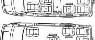
Location of alarms.
1 – indicator (orange) of low coolant level; 2 – indicator (red) of critical engine malfunction; 3 – indicator (orange) MIL; 4 – indicator (orange) “Attention” of the engine control system; 5 – signaling device (green) for turning on the left direction indicators; 6 – signaling device (white) for turning on daytime running lights; 7 – indicator (red) of abnormally high coolant temperature; 8 – signaling device (green) for turning on side lights; 9 – signaling device (red) “STOP”; 10 – signaling device (blue) for turning on the high beam headlights; 11 – indicator (orange) of the minimum fuel reserve in the tank; 12 – signaling device (green) for turning on low beam headlights; 13 – signaling device (green) for turning on the right direction indicators; 14 – indicator (red) of a malfunction of the electronic brake force regulator or reserve; 15 – indicator (orange) of a malfunction of the anti-lock brake system or reserve; 16 – indicator (orange) of open cabin doors; 17 – backup signaling device; 18 – indicator (green) of gas equipment operation; 19 – indicator (red) of battery discharge; 20 – signaling device (red) for turning on the parking brake; 21 – indicator (red) of an emergency low level of brake fluid in the brake master cylinder reservoir; 22 – indicator (red) of emergency low oil pressure.
1 – Warning light (orange) for low coolant level.
When the warning light comes on, it is necessary to eliminate the cause of the coolant leak and bring the level in the expansion tank of the engine cooling system to normal.
2 – Indicator (red) of critical engine malfunction.
Lights up briefly when the instruments (ignition) are turned on. If there are no malfunctions, it lights up when the devices (ignition) are turned on and lights continuously for 2-5 seconds, then goes out.
When lit continuously, it informs the driver about the presence of a critical malfunction (engine overheating, drop in oil pressure, gas pedal failure, critical malfunction of the electronic unit) in which case it is necessary to immediately stop driving and stop the engine.
3 – Indicator (orange) MIL.
Lights up briefly when the instruments (ignition) are turned on. Informs the driver about malfunctions recorded by the on-board diagnostic system related to exhaust gas and particulate emissions.
If the indicator lights up continuously, it is necessary to diagnose the engine control system at a maintenance facility.
After the malfunction is eliminated, the indicator remains on for four engine starting cycles, then goes out.
4 – Indicator (orange) “Attention” of the engine control system.
If the control system is working properly, the indicator lights up after turning on the devices (ignition) and lights continuously for 2-5 seconds, then goes out.
This indicates that the system is ready to start the engine.
When lit continuously, it informs the driver about the presence of a non-critical fault, in which case the driver can continue driving. In this case, the vehicle needs to be diagnosed at a maintenance facility.
5 – Signal lamp (green) for turning on the left direction indicators.
6 – Indicator (white) for turning on daytime running lights.
7 – Alarm (red) for abnormally high coolant temperature.
Lights up briefly when the instruments (ignition) are turned on. If the indicator lights up continuously, you must immediately stop the engine (in accordance with the subsection, determine and eliminate the cause of overheating.
8 – Indicator (green) for turning on the side lights.
9 – Signal indicator (red) “STOP”.
Lights up simultaneously with one of the indicators 2, 16, 19, 20 and 21. When these indicators light up, further operation of the vehicle is not allowed until the malfunction is eliminated.
Cooling system
Check the coolant level in expansion tank 2 only on a cold engine.
The liquid level in the expansion tank must not be lower than the MIN mark and not higher than the upper welded flange (MAX mark).
Add coolant through the expansion tank hole, closed with plug 1. If you add fluid frequently, check the tightness of the cooling system.
If the drop in fluid level is caused by a leak in the system, correct the problem and bring the level back to normal.
If the system is sealed, a decrease in level is possible as a result of boiling of the liquid when the engine overheats. The reasons for overheating may be the following:
- Reducing the flow of outside air to the radiator due to covering it with an insulating cover, severe clogging of the radiator fins (leaves, dust, insects), as well as installing additional headlights in front of the radiator trim.
- The fan is not working.
What is a “check engine”: what problems does a burning “check” indicate?
The warning light comes on for the following reason: the engine ECU detects some error or failure and writes the fault into its memory in the form of a specific code. In parallel with this, the control unit initiates the lightning of the check. Let us add that on some cars that have a developed self-diagnosis system, such an error can be immediately deciphered and the data is displayed on the on-board computer screen. Simpler versions of the car will require connecting a special scanner to the diagnostic connector, after which the error code is read for further detailed decoding.
It is worth noting separately that if the check engine light is on when you turn on the ignition, then this is an absolutely normal phenomenon and is not a malfunction. The icon should normally go out after the engine starts, that is, after the internal combustion engine begins to operate independently. A cause for concern is the situation when the engine is running and a lighted check mark is present on the panel after starting.
As already mentioned, the ECU records various errors, after which the check light comes on. This means that the malfunction can be either a serious breakdown or a minor problem. In any case, further operation of the vehicle is not recommended, since the car requires immediate diagnostics. At the same time, experienced drivers can independently determine the cause of the check light without going to a service station or using diagnostic equipment. Let's look at the main symptoms, signs and causes of common faults that cause the warning light to come on.
Seats
We recommend adjusting the driver's seat as follows:
- Using the adjustments, set the seat so that you can fully press any vehicle control pedal without experiencing discomfort;
- Set the backrest angle so that you can engage fifth gear without lifting your back from the seat back.
DANGEROUS!
To avoid creating an emergency, do not adjust the driver's seat while the vehicle is moving.
Driver's seat
The car can be equipped with a driver's seat in two versions.
Has the following adjustments:
- by angle of inclination;
- longitudinal;
- by the angle of the backrest;
- rigidity of the lumbar support.
To adjust the seat angle
Unscrew the lower nut 1, loosen the bolts 3 on the right and left, then, by rotating the upper nut 2, select the desired seat tilt position.
For longitudinal movement of the seat
Pull the longitudinal adjustment lever 4 up and select the desired seat position. After adjustment, make sure the seat is locked into place.
To adjust the seatback angle
Turn handle 5 as shown in the figure and select the desired backrest tilt position.
To adjust the stiffness of the lumbar support of the seat back
turn handle 6 as shown in the figure and select the desired lumbar support rigidity.
Driver's seat headrest
- unregulated.
Driver's seat (optional)
Depending on the vehicle configuration, the driver's seat in a variant version can be equipped with an armrest, electric seat heating and adjustable lumbar support of the seat back.
Has the following adjustments:
- longitudinal;
- along the height of the front part of the seat cushion;
- along the height of the rear part of the seat cushion;
- by the angle of the backrest;
- rigidity of the lumbar support.
For longitudinal movement of the seat
Pull the longitudinal adjustment handle 1 up and select the desired seat position. After adjustment, make sure the seat is locked into place.
To adjust the height of the front or rear of the seat cushion
lift up handle 2 or 3, respectively, and sequentially set the desired height of the front or rear part of the seat.
To adjust the seatback angle
Turn lever 4 as shown in the figure and select the desired backrest recline position.
To adjust the seatback angle
Turn lever 4 as shown in the figure and select the desired backrest recline position.
To adjust the stiffness of the lumbar support of the seat back
Press the balloon 5 and select the desired lumbar support stiffness. To loosen the lumbar support, press and hold button 6.
Driver's seat headrest (optional)
height adjustable.
To adjust the head restraint, press lock 1 and, while holding it, move (up or down) the head restraint to the desired position. Then release the latch and try moving the headrest to make sure it is securely fastened.
Passenger seat
The passenger seat is double, non-adjustable.
On the base of the passenger seat on the right side there are welded brackets for installing a fire extinguisher.
Required checks
The checks described below are simple but important. They must be done at regular intervals before travelling.
Daily checks:
- Check the condition and operation of lighting devices, sound signals, instrument panel indicators, windshield wiper and washer blades.
- Check the condition and operation of the seat belts.
- Check the operation of the brakes.
- Check under the car for traces of water, oil, fuel and other leaks.
Weekly checks (or before a long trip):
Checking the level/topping up:
- Motor oil.
- Coolant.
- Fluid in the windshield washer reservoir.
- Oil in the power steering reservoir.
- Brake fluid in the brake master cylinder reservoir.
- Presence of water in the fuel filter. If necessary, drain the water.
- Condition of tires and air pressure in them (including spare ones). If necessary, adjust the air pressure in the tires to the required level.
Monthly checks:
Check the operation of the air conditioner by running the engine for 10 minutes with the air conditioning system on.
Check the operation of the pre-heater by turning it on for 10 minutes.
Signs on the GAZelle Next dashboard
The updated model is equipped with two types of motors. At the same time, the dashboard mounted on a diesel engine is more complete than for a gasoline unit. The 2018 version of the dashboard has all the necessary indicators and indicators for comfortable use of the car.
Important! All indicators are divided into three colors:
- red;
- orange/yellow;
- green.
If the prohibiting indicators come on, further operation of the machine is strictly prohibited. The limit is considered to be reaching a service station. If the regulations are violated, the motorist may be denied warranty service - the information is recorded in the on-board computer.
Full decoding of the instrument panel indicators of a Euro-5 class car.
- 1 – an orange lamp indicates a failure of the particulate filter. When a signal appears, you must immediately diagnose the specified part for damage or patency. In case of heavy blockage, the element is replaced with a new one.
- 2 – lights up simultaneously with the above system. Notifies the driver if the engine exhaust temperature is too high. Indirectly indicates a malfunction of the particulate filter.
- 3 – antifreeze leak indicator. If an element catches fire, you must immediately stop and eliminate the loss of fluid, and also replenish the loss to the required level indicated on the wall of the expansion tank.
- 4 – Check Engine – lights up when critical engine faults are detected. If the indicator is active, operation of the vehicle is prohibited until the problem is resolved.
- 5 – the yellow element lights up briefly when the ignition is turned on. If after 10 seconds it does not go out, you need to check the exhaust cleaning devices and diagnose the ECM for system errors.
- 6 – the indicator means that a non-critical failure has been detected in the on-board system. If the device goes out 3-4 seconds after starting the internal combustion engine, everything is in order. After a planned shutdown, it is necessary to check the standard systems for errors.
- 7 and 15 – arrows indicate that the turn signals for the left and right sides are activated, respectively.
- 8 – white element indicating the inclusion of daytime running lights.
- 9 – engine overheat indicator. If the lamp comes on while driving - this indicates a critical coolant temperature - you should immediately stop the car to cool the system.
- 10 - the next indicator has an informative value - it indicates the normal operation of the side lights.
- 11 – STOP. When activated in parallel with similar red elements, it indicates the need for an urgent stop. In the event of a single fire, accompanied by characteristic sounds, it notifies about the activation of a request from the passenger compartment of the car.
- 12/14 – indicator for turning on the near/far mode of the head optics.
- 13 – the icon in the form of a gas pump means that you need to refuel. When activated, no more than 8 liters of fuel remain in the tank.
- 16/17/27 – made in the form of a schematic diagram of the car chassis and is located to the right of the display in the tachometer circle. Indicates that the center, front or rear differential is engaged respectively.
- 18 – requirement to fasten seat belts.
- 19 – is responsible for a similar element, indicates a belt failure or an error in the airbag unit.
- 20 – the same value as point 19. The only difference is that it indicates that the element being serviced is disabled.
- 21/23 – installed on the GAZzone Next of the latest years of production, it indicates a disconnection/breakage of the directional stability device.
- 22 – EBD failure or system error.
- 24 – green light, usually indicates that a downshift is engaged.
- 25 – breakdown of the ABS system; if it lights up constantly, you need to go to a service station to diagnose the device.
- 26 – the doors are not closed or the boarding step remains in the open position. Flickering indicates the front of the vehicle, steady light indicates the rear doors.
- 28 – installed only on diesel engines, indicates that the air heating is on.
- 29 – also used exclusively on diesel engines; it signals that water has entered the fuel filter. The lines and tank need to be flushed.
- 30 – the battery is dead or faulty. The battery needs to be replaced or charged.
- 31 – the car is on the handbrake, movement is impossible.
- 32 – (red watering can) critically low oil pressure. It may indirectly indicate a blockage in the lines or a serious leak of lubricant from the crankcase of the unit.
- 33 – breakdown in the brakes. The pressure inside the master cylinder has dropped - you need to show the car to the experts as soon as possible.
- 34 – the standard lamp indicates that the stern fog lights are on.
Refueling the bus
The fuel tank is located on the left side of the bus. To refuel the bus, open the fuel tank cap by turning it counterclockwise.
To close the fuel tank cap again, place it on the neck and screw it in clockwise until it clicks into place.
To operate the engine, it is necessary to use diesel fuel in accordance with GOST R 52368–2005 (EN 590:2004) type II or III.
Depending on the ambient temperature, it is recommended to use fuel of the appropriate class or grade indicated in the table:
| Fuel class | 1 | 2 | 3 | 4 | ||
| Application temperature, °C, not lower | -20 | -26 | -32 | -38 | -44 | |
| Fuel class | A | IN | WITH | D | E | F |
| Application temperature, °C, not lower | +5 | -5 | -10 | -15 | -20 |
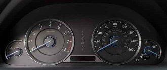
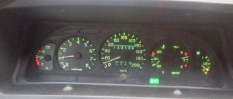
Dashboard GAZelle NEXT - instructions for use
The GAZelle NEXT instrument panel and controls are made in accordance with international standards and fully meet the requirements of accessibility and comfort. We bring to your attention detailed instructions for the GAZelle Next instrument panel.
- Tachometer. Displays the engine speed in revolutions per minute. We remind you that diesel engines have low operating speeds, so long-term load above 3600 rpm is highly not recommended.
- Engine coolant temperature. Everything is clear here. When the arrow reaches the red mark, the high temperature alarm is triggered, and you must stop driving, turn off the engine and figure out the cause of the overheating.
- Mode switch and trip computer control. By turning the button, you select the trip computer menu (clockwise - menu up, counterclockwise - menu down)
- Trip computer screen.
- Zero reset button for daily mileage, hour and minute settings. To reset the readings, hold the button pressed for 3 or more seconds. Rotating the dial clockwise will adjust the hours, and counterclockwise will adjust the minutes.
- Fuel level in the tank. The tank volume is 64 liters. When the fuel level reaches 8 liters or less, a sensor is triggered, signaling the need to refuel.
- Speedometer. Shows the vehicle speed in km/h.
Below are examples of different modes of presenting information by the GAZelle NEXT on-board (trip) computer.
Source
Where is the fuse located and how to replace it
The GAZ Next series family is represented by vehicles for various purposes - an all-metal van, an onboard vehicle, a bus for transporting passengers. Due to various design features, the marking and location of the fuse responsible for the cigarette lighter may vary. Cars have 3 fuse blocks:
- Engine compartment - under the hood of the car on the passenger side.
- There is 1 more switching device in the engine compartment on the driver's side.
- The third one is located inside the car under the steering wheel, to the left of the driver.
The cigarette lighter fuse, designed for a current of 20 A, is located in a block located in the vehicle interior. To access it, you need to pull the cover that closes the device towards you and remove it from the latches. In the left half of the mounting panel there is a control circuit relay, in the middle at the bottom of the block there is a diagnostic connector, and on the right side there are fuse links. They are divided into 2 columns of 12 fuses each. The markings go from bottom to top:
- left column - from F13 to F 24;
- right column - F1 to F12.
Depending on the year of manufacture, model and functional purpose of the car, the fuse link responsible for the operation of the cigarette lighter may be located in place F7 (seventh from the bottom in the right row) or F19 (seventh from the bottom in the left column). The fusible links on the circuit board are located compactly; to remove them from the socket, you must use special tweezers.
Warning icons on the panel
The steering wheel icon can light up in two colors. If the yellow steering wheel is on, then adaptation is required, and when a red image of the steering wheel with an exclamation mark appears, you should already be concerned about the failure of the power steering or power steering system. When the red steering wheel lights up, your steering wheel will probably become very difficult to turn.
The immobilizer icon usually blinks if the car is locked; in this case, the indicator of a red car with a white key signals the operation of the anti-theft system. But there are 3 main reasons if the immo light is constantly on: the immobilizer is not activated, if the tag on the key is not read or the anti-theft system is faulty.