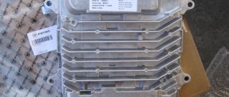
To increase engine power without increasing its volume, exhaust gas is actively used. It provides additional energy if you apply pressure to the vane mechanism so that it spins and captures more air.
The air flow is then fed into the engine cylinders and helps process the fuel. One of the auxiliary parts in this process is the actuator. What it is and how to eliminate various problems associated with it, we will analyze further.
How does a turbine protector work?
As we have already said, the exhaust gas and air that the blade mechanism (or simply turbine) captures is under pressure. Sometimes it increases too much, and it has to be reduced by releasing excess gas through a special valve - that’s what an actuator is, and it is simply necessary in a car with a turbocharged engine.
The operating principle of the actuator is to react to an increase in engine turbine speed - the valve opens and releases part of the exhaust gases, which, as you remember, help the blades to spin. Thus, the turbine does not receive enough driving force, and the pressure is released without reaching a critical point.
All this happens automatically: the designers calculate at what intensity of the force impact of the gas on the turbine it is time to reduce the speed, and it is when the specified value is reached that the valve is activated. Now you understand how an actuator works and why it is called a turbine protector.
If you just use the car without changing anything in it, and undergo maintenance on time, then you don’t have to worry - the actuator is already configured and will work perfectly. For those who are interested in tuning, especially those affecting the functionality of turbines and engines, there are a number of risks that can be avoided by learning how to properly configure the wastegate.
Checking the actuator
Initially, at the time of implementation, the actuator has factory settings and, in fact, is ready for operation. But after installation on the vehicle, it is advisable to check the actuator and adjust it. A typical signal to perform such actions will be the rattling of the compressor when the car engine is turned off. There is no need to panic here, this is not a breakdown of the actuator. The valve stem simply dangles excessively during operation.
In addition, often, if you configure the actuator correctly, you can significantly increase the performance of the turbocharger by increasing the air pressure supplied to the engine.
Adjustment is carried out in several ways
- The simplest and most common way is to simply replace the spring with a more powerful one. This will increase and maintain high turbine pressure until the exhaust valve is activated. But this is fraught with excess turbine shaft speed.
- The next option is to tighten (you can tighten or loosen) the regulator, which affects the process of opening and subsequent closing of the damper. As you relax, the pull lengthens. If you pull it a little, it shortens. The closure density of the damper directly depends on the length of the rod. The smaller it is, the tighter the damper will fit. Therefore, it takes more pressure and time to open it. Thus, the turbine is able to provide high speeds in a short period of time.
- Another option is to install a boost controller. The device is installed in front of the wastegate and provides a decrease in pressure at which the actuator membrane is activated. In fact, such a device takes on part of the pressure regulation function, as a result of which the valve does not receive information about the real gas pressure and continues to operate as normal.
How to check a turbine actuator
To check the actuator, it is best to remove the entire turbine and make sure there is no rust. Please note the following:
- The metal rod must move freely, deviating no more than 10 mm. and without making any clanging or other strange sounds.
- The membrane must be elastic, intact and not deformed. Slide the rod all the way up, insert the plug into the hole connected to the cuff - if the tightness is maintained, the rod will not move anywhere from its place. To be sure, it is better to wait a few seconds so as not to lose sight of even the smallest hole.
- The electronic elements of the actuator are checked at a service station - this requires a number of special tests.
All faulty parts must be replaced.
Common Wastegate Problems
Now let's talk about common malfunctions in which replacement of the turbine actuator is inevitable or repair of this element is required. Let's start with the fact that there are several reasons for the failure of this part. First of all, electronic components break down, the electric motor may malfunction, and the teeth of the valve drive gears also break.
In some cases, the problem is eliminated after diagnosis at specialized turbine repair services. Specialists check the functionality of the controller and perform a number of tests. A common malfunction that repair of a turbine actuator without replacement can help eliminate is a failed cuff (turbine actuator membrane).
We also recommend reading the article about what kind of device a diesel engine turbine has. From this article you will learn about the features of turbochargers for power units of this type.
In the mid-day case, significant mileage and natural wear of parts lead to breakdown, and as a result, the specified cuff is often damaged. To eliminate it, it is necessary to remove the turbine actuator, after which the old membrane is removed from the housing. Next, the surfaces should be degreased, after which the new cuff is glued to the body with two caps and additionally undergoes a circular rolling process. Then the turbine actuator is adjusted.
Advantages of servicing with us
Service specialists are ready to repair, replace or adjust the diesel engine turbine actuator in a short time. All repair or service work is carried out within 1 day from the date of request. In order to guarantee quality, we use only certified equipment and original parts from manufacturers. The experience of our specialists, the availability of modern diagnostic stands, and thoughtful service conditions make cooperation with us pleasant and effective! Leave a request or discuss your question with consultants, and we will help you sign up for diagnostics at the most convenient time!
Design
The design of a turbine with variable geometry differs from conventional models by the presence of an additional mechanism in the inlet part of the turbine housing. There are several options for its design.
The most common type is the sliding paddle ring. This device is represented by a ring with a number of rigidly fixed blades located around the rotor and moving relative to a stationary plate. The sliding mechanism serves to narrow/expand the passage for gas flow.
Since the blade ring slides axially, this mechanism is very compact, and the minimum number of weak points ensures strength. This option is suitable for large engines, so it is mainly used on trucks and buses. It is characterized by simplicity, high reliability.
The second option also assumes the presence of a blade ring. However, in this case, it is rigidly fixed to a flat plate, and the blades are mounted on pins that ensure their rotation in the axial direction, on the other side of it. In this way, the geometry of the turbine is changed by means of the blades. This option is more efficient.
However, due to the large number of moving elements, this design is less reliable, especially in high-temperature conditions. The noted problems are caused by friction of metal parts, which expand when heated.
Another option is a moving wall. In many ways it is similar to the sliding ring technology, but in this case the stationary blades are mounted on a static plate rather than on a sliding ring.
A variable area turbocharger (VAT) involves blades rotating around a mounting point. Unlike the scheme with rotating blades, they are installed not along the circumference of the ring, but in a row. Due to the fact that this option requires a complex and expensive mechanical system, simplified versions have been developed.
One of them is the Aisin Seiki variable flow turbocharger (VFT). The turbine housing is divided into two channels by a fixed blade and equipped with a damper that distributes the flow between them. Several more fixed blades are installed around the rotor. They provide flow retention and merging.
The second option, called the Switchblade design, is closer to the VAT, but instead of a series of blades, it uses a single blade, also rotating around the installation point. There are two types of this design. One of them involves installing a blade in the central part of the body. In the second case, it is located in the middle of the channel and divides it into two compartments, like a VFT blade.
To control a turbine with variable geometry, drives are used: electric, hydraulic, pneumatic. The turbocharger is controlled by the engine control unit (ECU, ECU).
It should be noted that such turbines do not require a wastegate, since through precise control it is possible to slow down the flow of exhaust gases in a non-decompression manner and allow the excess to pass through the turbine.
Why do actuators require repairs?
Often, actuator repair is necessary when your car does not drive as it should. You experience a significant loss in power. Incomprehensible sporadic jerks appeared. Vacuum actuators are more reliable compared to their electronic counterparts. Here everything is subject to depreciation: the spring and the membrane lose their properties, the connections between the valve and the stem wear out.
It is necessary to talk about external influences when a foreign object, oil, dirt, or water masses enter. If the vacuum actuator fails, then most likely a new one will be needed. Although in our service we can often restore the vacuum actuator to working condition. At times, the stumbling block becomes the basic search for necessary spare parts.
Most often, electronic actuators come to us for repair. The root cause of failure of actuators of this type is a problem with the turbine itself. Sometimes the rotor breaks, from case to case, a foreign object gets in. Bearings also wear out constantly.
Almost constantly we are faced with coking of variable geometry. Based on all this, the electric motor operates in critical conditions and expends more power to somehow move the geometry. At these moments, increased wear of plastic gears occurs. The electric motor itself also suffers.
Over the years, our specialists have mastered how to fix any breakdowns of electronic actuators. Having modern equipment and machines in our arsenal, we restore 1-2 actuators every day. The disassembly and assembly process occurs quickly. Restoration of actuators also occurs with the replacement of necessary spare parts and proper tuning with a special tester at the end.
You shouldn’t buy a new actuator right away when repairing the old one will cost you 1.5-2 times less. It should be noted that some actuators are sold only with a turbine. Repairing the actuator is the right solution.
When a turbine arrives to us, the first thing we do is check the functionality and correct operation of the actuator. And then we move on to consider the entire turbine. Come visit and bring your turbines with actuators. Let us help you save money and enjoy your journey for many years!
Actuator device repair
Repairing the Corolla E150 clutch actuator will stabilize the operation of the robot. Do-it-yourself repair procedure.
Check clutch
To do this, you need to accelerate the vehicle to 50–60 km/h, switch the robot to manual adjustment mode and engage fifth gear. In this case, you need to depress the gas pedal as much as possible and make sure that the speedometer and tachometer needles move synchronously. This indicates that the clutch is working properly.
Determine actuator error
To determine possible errors, it is necessary to stop the machine, move the robot to the neutral position, turn off the parking brake and the ignition system. Using SST, connect the TC and CG pins of the DLC3. Next, you need to turn on the ignition system, while releasing the brake pedal. The diagnostic system will start. All dashboard lights will flash, and if an error occurs, a red gear will appear and flash at regular intervals. If no errors are found, then blinking will occur without long breaks.
Remove and disassemble the MMT
In order to troubleshoot the actuator, it must be removed. You can get to the mechanism only by removing the battery and its platform. Then it is worth disconnecting the chips from the engine and sensor. Afterwards, you can remove the actuator directly (it is secured with three bolts).
Next, the engine is disconnected from the actuator, and the internal space of the mechanism is cleaned of dust and dirt.
Replacing brushes should be carried out with extreme caution, since new breakdowns are possible during this process. You should immediately check the Corolla 150 clutch actuator motor; to do this, you need to look at the wiring
There should be no plaque, dirt or “oldness” on it. If there is an unpleasant burning smell, it means that the actuator motor has burned out and should be replaced.
Next, you can disassemble the MMT. To do this, you need to unscrew the fastening elements of the sensor; it is also worth remembering the exact location of this part. After the sensor has been removed, you need to find a plate with antennae; it is attached to nuts that need to be unscrewed. To determine the correctness of the disassembly process, the rod is placed in a certain position. To do this, you need to take a screwdriver and turn the rotating element in the groove of the drive motor. The rod should be extremely compressed inward.
Afterwards you can dismantle the fastening elements and open the MMT cover. Next, the drive rod is untwisted and pulled out. It is necessary to clean the mechanism from old grease and clean the block from dirt and dust.
After cleaning, it is necessary to diagnose the MMT for the presence of possible breakdowns. One of the simplest diagnostic methods is the following: you need to pull out the spring and assemble the entire mechanism to check. Most often, bushings wear out, and the most common problem is a poorly manufactured drive. Therefore, before purchasing a new actuator, you should ask yourself: where is this important mechanism made?
Install the device
During assembly, all components are installed in the reverse order. In this case, it is necessary to lubricate all bushings, bearings and the worm shaft. After installing the actuator, the rod is placed in its outer limit position and “started” half a turn. The sensor is placed on the antennae, after which the part is rotated clockwise, this is necessary to fix the sensor with fasteners. Afterwards you need to lubricate the clutch fork, install the drive, chips on the motor and the drive sensor.
In the end, all that remains is to install the battery and adjust the clutch position.
How to extend the service life of a product
Using simple rules, you can seriously extend the life of both individual elements of the turbocharger (including the vacuum regulator) and the entire device as a whole. The following describes the operational features in different engine operating modes:
- Start the engine. When starting, try to use gas to a minimum, and keep the engine at idle speed for at least a minute. The fact is that in a turbocharged compressor the necessary parameters are established within a few seconds if good lubrication is supplied. If you turn on the gas at the very beginning of the power plant start-up, the impeller will be forced to spin in conditions of insufficient oil supply, which will lead to its breakdown.
- Start in winter. If the engine has not been running for a long time or you have to start the engine at sub-zero temperatures, start only at idle speed so that the oil fills the turbocharger.
- Stopping the engine. Before the ignition is turned off, let the power plant run for a while on XO. Otherwise, temperature changes will occur in the turbocharger, and oil will abruptly stop supplying the components of the device, which will still spin by inertia.
- Idle speed. It is not recommended to keep them for more than half an hour. If this time interval is exceeded, the impeller will rotate at insufficient speed, which risks the penetration of oil vapors through the connections. As a result, a bluish exhaust appears from the muffler.
- Actions before starting the engine for the first time after a major overhaul. First make sure the turbocharger lubrication system is full. Next, without starting the engine, turn the crankshaft so that the oil begins to circulate. Start the engine and let it idle for ten minutes.
Compliance with these recommendations will extend the life of the turbocharger and avoid premature adjustment, or even costly repairs.
Toyota Corolla — Clutch actuator upgrade
Do-it-yourself tuning of Toyota Corolla 120
Hi all! Today I will tell you about how I upgraded the actuator (clutch servo) on my corolla and what preceded it. Let's get started! One wonderful frosty early morning, I and my family once again went to work. Having traveled some distance through morning traffic jams at the next traffic light, my chariot refused to take me further, displaying the ill-fated gear on the instrument panel
the same gear and the blinking letter N. After manipulating the diagnostic connector (as described in the first entry in my logbook), lo and behold, she drove and even drove her to work, but the happiness did not last long, exactly until the next rush hour on the way to her home. Now the cart could not be manipulated in any way. After towing to the parking lot and disassembling in the form of removing the battery, further to the platform under it with 8 bolts of 12
Full size, remove the battery mount with a 10mm wrench and the battery stamps also with a 10mm wrench, then the battery itself
Full size 6 x 12 bolts
Full size2 bolts 12
we've reached our goal
Full sizeHere is the guy in the guise of an acuator)))
The autopsy showed that due to excessive wear of the brushes of the actuator electric motor and accompanying physical processes, it overheated with the melting of the varnish with which the rotor was filled, and as it turned out later, an interturn short circuit of the rotor winding occurred.
Full sizeThis is what's left of the brushes
Full size of the brushes. Next, I opened the actuator itself, I won’t post photos since there are already plenty of them on the Internet, I’ll tell you what I saw there, but I saw wear, again excessive shaft bushings and as a result of this there was a misalignment of the shaft and an increasing load on the electric motor, an increase in strength current up to 25A on the electric motor and turning it off by the controller (notifying the coachman about this in the form of a gear on the instrument panel).
After some time in thought, understanding the current situation and reading a ton of information, I decided to repair, or rather modernize, the clutch actuator
Full size Toyota Corolla, Auris, Corolla Verso actuator. The plan was to send it to the factory and use a jig boring machine to bore and mount the bearings at the locations of the sliding bushings (sliding bearings) as described. During the process of work and consultations, the plan was finalized. The result was that in place of 2 bearings there were 3 (lower 9-26-8, 200 rubles, upper 2 pieces 9-17-4, 200 rubles each). The original shaft is 9.8 mm. Requires grinding up to 9 mm. Boring for the bearings on the top cover was made from the side where the sensor is located. The axial displacement was adjusted using washers. The issue price is 4000 rubles. I bought the electric motor used for 3,000 rubles. since the new price is too high: 9600 rubles
Full size electric motor, the new electric motor is equipped exactly like this. True, this was preceded by an unsuccessful repair of the old electric motor, on which I spent as much as 1,700 rubles. After assembling and installing everything in its regular place according to the marks, the boulevard drove off, of course there was joy, but with increased attention to the sounds and behavior of the car. After one full day of traveling, the engine and gearbox were trained and by evening everything was back to normal
The shifts are smooth, there is assistance at start, the idle speed has leveled off at around 600 - 700 rpm.
I will continue from the first words of this article. One wonderful frosty early morning, I and my family once again went to work. Having traveled a certain distance through morning traffic jams at the next traffic light, my chariot refused to take me any further, displaying the ill-fated gear on the instrument panel! You won’t believe it at that traffic light, at the same one! After manipulating the diagnostic connector (pressing the clutch), she drove off, but with delayed clutch release. While searching for an answer on the Internet, I read an interesting article on one of the forums from a ton of flood. This is how the principle of operation is described
in a muffled state and with the ignition off, the gap between the linkage and the clutch fork should be 0.5-1 mm.
Full size required gap I made the adjustment as required and the machine immediately came to life, everything that was not there appeared, help with starting smooth switching. Next will be test test test. All sensations will be recorded in my on-board journal. Thank you all for your patience in reading my next article. May God, Allah, and Buddha protect you from such misfortunes. All the best!
Lubrication system
The turbocharger shaft is lubricated by the engine lubrication system.
O-rings are installed on the shaft to prevent oil from penetrating into the cavities of the compressor and turbine housings. They also protect the housing from overheating. But tightness is ensured not so much by seals as by the difference in pressure in different parts of the unit. This pressure difference is created by a turbine axis (shaft), which has an uneven diameter.
The special casting shape of the housing in which the shaft is located also helps retain oil.
If the engine does not develop the required power, this may be a symptom of a turbocharger failure. The most common problems are a dirty air filter or loss of airtightness in the intake manifold. In addition to loss of power, they can be diagnosed by the color and amount of smoke coming out of the exhaust pipe, which is unusual for a working car.
Removal algorithm
As for removing the element, with all three replacement methods without removing the panel, dismantling is performed in the same way. The algorithm for removing the heater radiator is as follows:
- Drain the antifreeze from the cooling system.
- We dismantle the engine air filter along with the air duct.
- Disconnect the battery terminals and remove the battery from the car.
- Remove the battery mounting plate.
- Under the steering rack we find two pipes through which coolant is supplied to the heater radiator, loosen their clamps and pull the tubes off the fittings.
- Near the fittings we find a nut that secures a mounting plate with a rubber seal through which the heat exchanger fittings pass to the engine shield. unscrew this nut.
- Let's go to the salon. On the driver's side, remove the decorative side trim of the center console.
- Unscrew the gas pedal and move it to the side.
- We remove the brake light sensor located near the brake pedal.
- Since it will not be possible to remove the brake pedal without dismantling the steering column and mechanism, we do this. We remove the bracket for fixing the pin that connects the brake pedal to the vacuum booster, remove the pin and bend the stop plate of the brake light sensor. After this, we lift the pedal up and it does not interfere with removing the radiator.
- Unscrew the three screws securing the radiator to the body.
- Since the radiator outlet is blocked by fittings, they need to be sawed off or broken off.
- After sawing off the fittings, the radiator will “come out” of the seat.
But dismantling the heat exchanger is only half the battle; you still need to install a new element, but the fittings prevent this from being done.
Definition of the concept
So, an actuator - what is it? The word itself is very similar to another similar one - “activator”. The concept of both is almost the same. An actuator is a technical device or trigger mechanism that transmits force from the controller to the controlled object. The impact itself can be varied: from linear to rotating. At the same time, depending on how the force is applied, the variety of devices is determined.
In automotive specifics, the actuator can be represented by a central locking drive. The force from the control circuit is transmitted here into linear movement by a worm gear. But the simplest automobile actuator is a mechanical jack. Here the node manager is a person. And the actuator transmits the rotational action into the vertical movement of the jack platform. This refers to the simplest mechanical device made in the form of a trapezoid.
Consequences of resetting the ECU
The clutch is not working stably: firstly, the electronic control unit will set a new reference point, as a result of which discrepancies may arise in the operation of the clutch disc. There is a great danger of severe wear of the clutch - the ECU will update the sensor readings, which will no longer display the actual degree of wear of the clutch disc. Well, if the clutch is badly worn, then errors and breakdowns associated with the robotic gearbox may occur. The speed of movement of the disk will also decrease, and this leads to the appearance of error P0810.
The result of all of the above malfunctions is the inability to move in such a car.
Design features of the vacuum regulator
The most widely used devices are Bypass type, which are offered in two versions:
- Closed cycle turbine actuator. Here, excess pressure enters the heated sector of the device through the bypass channel. This technology reduces inertial losses that occur when the turbine wheel increases its speed. When excess pressure is generated, the diaphragm begins to bend. As a result, the force of the return spring is overcome, the device opens and everything “extra” flows into the bypass channel.
- Blow-Off. The “pump principle” also applies here. The difference is that the excess is released into the atmosphere: the process is accompanied by a characteristic sound.
Design features depending on application
Engineers integrating linear actuators into equipment must have a detailed understanding of their operating conditions to determine which design to use in which situation. This is done for economic reasons, since the shorter the drive’s operating cycle, the more expensive it is.
For example, the print head in a printer must be positioned very precisely above a sheet of paper. Brake cylinders in a car, on the other hand, must absorb large amounts of energy in order to reduce braking time and the distance to a complete stop.
The hydraulic cylinders on large excavators used in construction must be able to move hundreds of kilograms of load with relatively little error.
Electronically controlled linear actuators used in the small-part assembly process move at blinding speeds and assemble hundreds of microchips in a fraction of the time.
As can be seen from the above, linear actuators, although they have common design features, are very different from each other in application. This is due to many factors: load on the device, size, operating speed and much more.
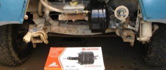
Installing a turbocharger on a car is one of the most effective options. With proper selection, installation and configuration, this unit seriously increases the engine power (up to one and a half times). Among the various design options, the most common are high-pressure devices equipped, unlike other models, with a bypass valve. It serves to ensure stable operation of the power unit at high pressure and high speeds. It should be noted that diesel engines do not have separate emergency pressure relief systems: all regulatory processes are carried out using the geometry of the turbine and the volume of the fuel-air mixture supplied to the cylinders. How the device is operated on gasoline engines and how the turbine actuator is independently adjusted is described below.
Linear motion actuators: do it yourself
We will not consider the reasons for wanting to make a linear actuator with your own hands. We'll just tell you how to do it. The easiest way to get, say, a door actuator is to use an electric motor. Now they are quite popular and affordable. Their cost can range from 50 to 200 rubles, depending on the parameters.
The sequence of manufacturing work can be as follows:
- A threaded rod is attached to the motor axle.
- A nut with a rod attached to it is put on it. As the engine rotates, the nut moves along the stud. The rod moves with it.
- The thread pitch is selected. Thanks to this, you can adjust the speed of movement of the rod.
It's even easier to get a linear drive if you get a gear rack. The speed of force transmission will be the fastest. But there is one minus. Thus, the transmission force, on the contrary, will remain at its lowest level. M20 and larger diameter studs transmit maximum energy. Here is our homemade linear actuator and it’s ready. Door locks in most cars operate on this principle.
What types of actuators are there?
There are two types of actuators popular in most turbines: vacuum actuators and electronic actuators (ECU, Electronic Turbine Control Units). As noted above, vacuum actuators are capable of opening and closing the wastegate valve. Moreover, they are able to control the variable “geometry” of the TIG turbine (change in the cross-section at the wheel inlet).
As for the design of vacuum actuators, everything is quite simple: inside the mechanical unit you can find a membrane and a working spring. If we are talking about electronic actuators, then these are more complex units. The electronic actuator contains a control unit and an electric motor. The motor moves the rod so that it opens the overboost valve each time.
Actuator replacement: when is it required?
Sometimes the turbine fails immediately, but usually it happens gradually. To detect a breakdown at an early stage, you need to take a closer look at the operation of the machine. If all efforts to repair this device fail, you will have to buy a new actuator.
Previously, replacement was carried out together with the turbine, but now the actuator can be replaced separately. Some technicians generally recommend not trying to repair this device, but replacing it immediately - unless, of course, the problem is a soured connection. The unit will definitely have to be replaced if the rod joint on the regulator is worn out. This work is not that difficult. After replacing the device, it will take time to adapt.
Aggressive driving style and the use of low-quality fuel and engine oil lead to premature failure of the actuator. In order for the unit to last longer, this should not happen - it is better to use only certified technical fluids.
The turbine drives oil into the intercooler: what to do?
The oil in the intercooler can cause serious malfunctions, including failure of the internal combustion engine. In this article we will tell you why oil appears in this unit and how you can fix this problem.
How to repair a turbocharger?
A turbocharger is a part that can significantly reduce engine fuel consumption. Repairing a turbocharger is quite difficult; professional tools are required.
Turbocharged engines and features of their operation
Turbocharged power units: their design features, performance characteristics and the most common causes of breakdowns.
Application of two-way valves in automotive systems
Since numerous vehicle systems constantly require shutting off, redirecting and mixing various flows of liquids or gases, the use of various bypass devices, such as valves, is required. The principles of their operation are based on different drives: pneumatic,
Turbocharging system on diesel engines
Many modern cars use turbochargers to increase engine power. They come in different types and shapes, but the principle of their operation is the same. The idea of turbocharged engines arose a long time ago. Some of the first turbochargers were installed on racing cars at the beginning of the last century.
Operating principle and design of the actuator
As noted earlier, a working valve is capable of reducing exhaust gas pressure when the power unit operates at maximum speed. To do this, it is mounted in the exhaust manifold of the car before the turbine. If the engine starts to operate at maximum speed, the gas pressure increases, the valve tends to allow gases to bypass the turbocharger wheel. When the actuator opens, exhaust gases escape through it, and more air enters, which contributes to the rapid acceleration of the supercharger.