During the Soviet era, great attention was paid to the development and production of special equipment. Therefore, the T-150 tractor, the creation of which began precisely in those years, is distinguished by its exceptional reliability and unpretentiousness, and is suitable for use in different climatic zones. The T-150 tractor is designed to solve a wide range of tasks in agriculture, road construction and maintenance, logging and other industries, including the armed forces.
The T-150 wheeled tractor is also maximally unified with the T-150 tracked model in terms of a wide range of components and parts. The design and production of a family of two machines is associated with a number of technological and design difficulties. At the same time, this allows us to reduce the cost of providing equipment with spare parts, consumables and components. This approach is used by John Deere, which produces both the 8120 and 8120T models.
History of the creation of the T-150 tractor
The production of this model was mastered by the Kharkov Tractor Plant more than 40 years ago. The first T-150 tractor left the assembly line in 1971 much earlier than the tracked modification. It is the wheeled vehicles of this manufacturer that are most widespread in the national economy. The prototype for the creation of the T-150 was the T-125 tractor of the original design. The machine was developed by the plant's engineers, as they say, from scratch, based on general requirements and technical specifications. The predecessor was produced from 1962 to 1967; a deep modernization of the model led to the appearance of the T-150. This allowed it to successfully pass international tests in the United States of America in 1979. The modification turned out to be extremely successful, the tractor is still in production. The machine is supplied to many countries around the world and operated in different climatic conditions. Often, equipment does not receive proper routine maintenance while remaining operational. These circumstances indicate a significant margin of safety and a huge resource of mechanisms and systems.
Since the start of production, the tractor has been modernized several times. In particular, the engine was replaced, and the machine control systems are constantly being improved. Much attention is paid to improving the working conditions of tractor drivers. This allowed KhTZ to largely maintain its position in this market segment.
Tractor HTZ T-150/T-150K - a completed project of a powerful station wagon
The design of the high-power general-purpose tractor HTZ-150 is one of the most successful developments by the designers of the Kharkov Tractor Plant. When creating the wheeled and tracked version, the latest trends in European mechanical engineering and our own developments were used. Both versions are distinguished by different designs of frames, gearboxes, control systems and turning mechanisms.
The project of the new tractor of the 150th model involves original technical and design solutions, as well as rich practical experience in operating the basic T-125 tractor. The first tractor in its series, the T-150, rolled off the assembly line of the Kharkov plant in 1967; over the next 4 decades of production, the model was repeatedly subjected to significant modernization.
A wheeled tractor of the 3rd traction category with an all-wheel drive chassis has proven itself in all respects in the agricultural sector, industrial construction and transport work of varying complexity.
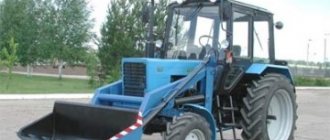
Photo: tractor HTZ T-150K
The wheeled and tracked version of this model is designed to work with high-performance agricultural machines.
Technical characteristics of T-150
The model is a wheeled tractor designed and manufactured using an articulated design. It is based on a frame consisting of a front and rear part connected to each other by a hinge. This design provides the machine with high maneuverability. Changing the direction of movement of the T-150 tractor is carried out by rotating the semi-frames around a vertical axis on a hinge joint. Control is carried out using a round steering wheel. The actuator is a hydraulic drive powered by a gear oil pump. The front half-frame houses the power unit, transmission, driver's cabin with controls and controls. To make the ride smoother, the axle is mounted on semi-elliptic leaf springs; the rear axle is rigidly connected to the supporting structure. Torque transmission is carried out using a cardan shaft mounted openly. The tractor has a wheeled propulsion type, with all-wheel drive on both axles. The diameter of the front and rear discs is the same; they are equipped with low-pressure tires measuring 1440 x 510 mm with developed lugs. This ensures high maneuverability of the tractor and the ability to move and perform work off paved roads. • Maximum traction force (traction class) – 3 tf. • Forward speed – 1.8 – 30.1 km/h, reverse – 6.6 – 10.4 km/h. weight in running order - 8 tons. • Working brake system - pneumatic drum type, actuated by a pedal or a crane. • Parking mechanism - a belt locks the shaft, actuated by a lever. the SMD-60 and SMD-62
brands as the power unit . This engine was specially designed for this family of tractors and had the following characteristics: • Type - four-stroke, liquid-cooled and turbocharged. • Rated power – 165 hp. (121.4 kW). • Number and relative arrangement of cylinders - 6 V-shaped with a camber angle of 90 degrees. • Crankshaft rotation speed - 2100 rpm. • Specific fuel consumption – 185 g/hp. h. • Engine weight with attachments - 1110 kg.
The power unit
is started using a two-stroke petrol engine P-350 with a power of 13.5 hp.
In turn, the starting motor is turned on by an electric starter or manually by a sharp jerk with a rope wound on a pulley. lubrication system
has two cleaning stages: a centrifuge to remove large particles and a paper filter element to retain small particles.
The oil pressure in the circuit is created by a gear pump, which is driven by the crankshaft. The power supply system
of the power unit includes a high-pressure fuel pump (HPF), injectors with four-point injection and a two-stage fuel purification system. A tank with a capacity of 430 liters is provided for fuel.
Subsequent modifications of the tractor are equipped with YaMZ-236 engines produced by Yaroslavl. The rated power of the power unit is 180 hp. at 2280 rpm. This allows the tractor to develop a traction force of 3 to 6 t, which ensures high productivity when carrying out agricultural and other types of work.
Brackets are riveted to the longitudinal beams for fastening the crank axle and support rollers, for the ball support of the guide wheel tensioner and intermediate links of shock-absorbing devices.
At the rear, cast brackets are riveted to the longitudinal beams for installing the rear axle. Tow hooks are attached to the front frame beam.
The caterpillar drive includes a chain, a drive sprocket, a guide wheel with a tensioning mechanism and a shock absorber, support rollers and support rollers.
The new track chain consists of forty-seven links. Each link is a shaped steel casting. There are four lugs on one side of the link and three on the other. Each eye is equipped with a spur. All spurs, except the outer ones, are rotated relative to the axis of the eyes by 20°. This ensures reliable adhesion of the tracks to the supporting surface when the tractor moves on a side slope on frozen soil and during icy conditions.
On the inside of the link there are guide protrusions passing between the support rollers and treadmills. The articulation of the treadmills is made with overlap, which ensures shock-free rolling of the track rollers.
The fingers connecting the links are made of steel. On one side they have stamped heads, and on the other side there are recesses into which rings are installed to keep the fingers from falling out.
Rice. 1. Crawler mover: 1 - idler wheel, 2 - cylinder, 3 - shock absorber, 4 - support roller, 5 - drive sprocket, 6 - support roller, 7 - chain, 8 - washer, 9 - ring, 10 - pin
When running straight, the teeth of the track chain drive sprocket should rest against the eye on the outside of the link.
The guide wheel is a steel casting with one rim and five shaped spokes, reinforced with stiffeners. Windows between the spokes make the wheel construction easier.
The wheel rotates on two tapered roller bearings, the inner races of which are mounted on the crank axle. The wheel is held against lateral movement by a washer and two nuts screwed onto the threaded end of the axle. The outer bearing races are pressed into the wheel hub bores. The bearings are lubricated with diesel oil through the central hole of the cover with a plug. There is a cardboard gasket under the lid. A sealing device is installed on the inside of the wheel to prevent oil leakage. This device consists of a housing screwed to the end of the stumica, movable and fixed o-rings and a pressure spring. The spring presses the rings tightly, retaining the lubricant. On the inner surface of the fixed ring there is an annular groove in which a rubber sealing ring is installed.
The journals of the upper axle leg are inserted into cemented steel bushings pressed into the bracket on the frame. When the tracks are tensioned and while the tractor is operating, the cranked axle rotates freely in the bushings, which are lubricated with grease pumped through an oiler. The crank axle is kept from lateral displacement by a washer screwed to the end of the axle.
The lower knee of the axle is pivotally connected to the rod of the track chain hydraulic tension cylinder. The cylinder body communicates with the shock absorber through an intermediate link.
To tension the track chain, unscrew the plug and pump solid oil into the working cavity of the cylinder through an oiler using a syringe. The pressure created in the cylinder acts through the seal and rod on the crank axle, which, turning in the bushings, moves the guide wheel forward and tensions the track. The tension force of the track chain during overloads is limited by a valve mounted in the housing. The valve body itself is used to relieve track tension.
The shock absorber, which protects chassis parts from damage when hitting obstacles, consists of two compressed cylindrical springs mounted on a tension bolt. One end of the tension bolt is connected to a fork, pivotally mounted on the intermediate link, and the other rests through a ball joint on a bracket on the frame. The compression of the springs is regulated by a nut, which acts on the support washer through a spacer sleeve. The normal distance between the ends of the springs is 525 mm.
As the tractor moves over an obstacle, the tension on the track chain increases and the idler wheel moves back. The cranked axle, turning in the bushings, moves the cylinder and the tension bolt back, the spring is compressed, softening the push received by the tractor. After moving over the obstacle, the springs unclench and return the cranked axle with the guide wheel to its initial position.
Rice. 2. Guide wheel with shock absorber: 1 - guide wheel, 2 - crank axle, 3 - oiler, 4 - cylinder, 5 - intermediate link, & - nut, 7 - springs, 8 - tension bolt, 9 - fixed o-ring, 10 — movable sealing ring, 11—seal housing, 12—adjusting nut
Rice. 3. Tensioner cylinder: 1 - nut, 2 - plate valve body, 3 - cylinder oiler, 4 - plug, 5 - cylinder body, 6 - rod seal, 7 - rod
The support roller limits sag and lateral movement of the track chain. There are two support rollers installed on each side of the tractor frame. Each roller has a hub, an axle and a bracket. The axle is pressed into a bracket, which is secured to the frame bracket with five bolts.
The hub is made in the form of a hollow cast iron with two thickened rims, on which replaceable rubber bands are put on. On the outside, the rubber band is pressed to the hub by a cover, and on the inside, by the seal housing. The support roller rotates on an axis in ball bearings, which are lubricated with diesel oil through a hole in the cover with a plug. The oil in the bearings is retained by the same sealing device as that of the idler bearings.
The support roller is kept from moving by a washer and two nuts screwed onto the outer end of the axle.
The suspension connects the tractor frame with the crawler tracks and ensures a smooth ride. It includes four balance carriages (Fig. 102), which are installed on the frame axles, two on each side. They are kept from lateral displacement by a washer with a bolt and a cover.
The carriage is a trolley consisting of two identical balancers cast from steel. Bushings are pressed into the central holes of the balancers, rubbing along the surface of the axles. The bushings are lubricated with diesel oil poured into the holes of the covers. These holes are closed with plugs. The lubricant in this joint is retained by a gasket installed under the cover and a seal unified with the sealing device of the road wheels.
In the hub of each balancer there is a boss with a bored hole into which the axle of the track rollers is mounted on tapered roller bearings. Rollers are pressed onto both sides of the axle and are held against lateral displacement and rotation by keys and nuts.
The outer races of tapered bearings have a sliding fit. The displacement of the bearings in the axial direction is limited by the ends of the seal housings. Gaskets are located under the seal housing to adjust the axial clearances of these bearings.
The bearings are lubricated with diesel oil, pumped through a channel, the outlet of which at the outer end of the axle is closed with a plug. The oil in the bearings is retained by a sealing device (the design is the same as that of the guide wheel bearings) and rubber rings installed under the roller mounting nuts.
In the upper part of the balancers, cup-shaped recesses are cast into which the ends of two spring springs fit. The outer and inner springs have different directions of turns to prevent them from jamming together. The springs tend to spread the upper ends of the balancers and lower the support rollers down, and the mass of the tractor compresses the springs and brings the upper ends of the balancers together. Thus, the weight of the tractor is transferred to the road wheels through a spiral spring, which ensures smooth running of the tractor.
Vibrations that occur when the tractor moves are damped by hydraulic shock absorbers mounted on the front carriages and mounted on brackets fixed to the top of the balancers. The hydraulic shock absorber consists of a cylinder, a rod with a seal and a compensation tank.
When the carriage is loaded, the shock absorber is compressed, and liquid from cavity B, under the pressure of the rod, flows into cavity A through the throttle hole, and through the throttle hole is forced into the cavity of the compensation tank. When the hydraulic shock absorber is sharply compressed, the bypass valve comes into action, which opens a number of additional holes to bypass fluid from cavity B to cavity A, which protects the shock absorber parts from damage.
When the shock absorber is stretched (Fig. 103, c), liquid from cavity A flows into cavity B through the same hole; from the compensation tank, liquid freely flows into cavity B through open valve 8. The hydraulic shock absorber increases the smoothness of the tractor and improves the working conditions of the tractor driver.
The hydraulic shock absorber uses AC spindle oil as the working fluid.
Rice. 4. Support roller: 1 — seal housing, 2 — sealing device, 3 — roller bracket, 4 — rubber band, 5 — hub, 6 — axle, 7 — cover, 8 — filler plug
Rice. 5. Carriage: 1 - spring, 2 - hydraulic shock absorber, 3 - balancer, 4 - shims, 5 - seal housing, 6 - axle of road wheels, 7 - sealing device, 8, 9 - plugs, 10 - axle sealing device, 11 - bushings, 12 - washer, 13 - bolt
Check the oil level with a dipstick mounted in the control plug.
Maintenance of the undercarriage of a crawler tractor. Maintenance of the chassis consists of tightening bolts, checking the oil level and replacing it, adjusting the slack of the track chain and tapered bearings.
Every shift, clean the components and parts of the chassis from dust and dirt. Check the fastening of bolts and nuts and whether oil is leaking through the seals. Inspect the rubber bands of the support rollers and remove foreign objects from the rubber. In winter, check whether the support rollers rotate freely.
After 60 hours of tractor operation, check the oil level in the bearings and, if necessary, add it: at the guide wheels - until oil begins to flow out through the holes in the cover; for support rollers - until oil appears from the gap between the tip of the oil supercharger and the wall of the oil channel; for support rollers - to the level of the filler hole when it is located 45° above the horizontal plane.
For the bearings of the running system, motor oil M10 G or M10 V is used as the main lubricant in summer and M8G in winter. It is allowed to fill the chassis system with diesel oil DS-11 in summer and DS-8 in winter.
After 240 hours of tractor operation, check the oil level in the balancer axles and hydraulic shock absorbers. If necessary, add oil to normal level. Monitor the tension of the track chain and, if necessary, adjust it.
After 960 hours of tractor operation, the oil in the bearings of the guide wheels, support rollers and support rollers, balancer axles and hydraulic shock absorbers is replaced. Lubricate the crankshaft bushings with solid oil “C”, making 5-8 injections with a syringe.
Check the axial clearance of the bearings of the guide wheels and road wheels, and if necessary, adjust it. Remove the hydraulic tension cylinders of the tracks, disassemble them, remove the grease, wash the rod and the inner surface of the cylinder. Place 300 g of pure solid oil in the cylinder and collect it. The stroke of the rod of the assembled cylinder must be free.
The track tension is checked on a flat and solid surface. The track section between the drive sprocket and the rear road wheel must be tensioned. The distance from the fingers of the most sagging link to a flat strip laid on the ends of the fingers of the links located above the supporting rollers is measured with a ruler. For normally tensioned track chains, this distance should be 40-60 mm and the same for both tracks.
If the tracks sag by more than 60 mm, clean the plug from dirt and use a syringe to pump solid oil through the oiler into the cylinder cavity. The length of the pre-compressed shock absorber spring should be 525 mm.
Axial clearances in tapered bearings should be checked with the tracks removed and the idler wheels and road wheels raised above the ground. The gap is determined by lateral rocking of the guide wheel manually, and for support rollers - using a crowbar. The normal axial clearance in tapered bearings should be 0.2-0.5 mm. If the axial play exceeds 0.5 mm, the bearings are adjusted.
The cover of the guide wheel is cleaned of dirt and removed along with the cardboard gasket. Drain the lubricant from the wheel hub, loosen the locknut and tighten the adjusting nut until the wheel turns tightly onto the rim by hand, and then unscrew it 1/6 of a turn. After making sure that the guide wheel rotates freely, tighten the locknut, install the cover and pour oil into the bearing.
To adjust the bearings of the road wheels, lift the tractor frame with a jack and remove the carriage from the axle. After cleaning the carriage from dirt, remove the support rollers and seal housings, wash the seal and bearing parts in clean diesel fuel, remove the same number of shims on both sides, replace the seal housings and tighten the bolts.
By hitting the ends of the axle several times with a copper hammer, check its axial play. If the play is not noticeable, and the axle rotates freely with a little hand effort, then the bearings are adjusted correctly. If the roller axle is difficult to rotate, add one spacer 0.2 mm thick.
Rice. 6. Hydraulic shock absorber and diagram of its operation: a - device, b - diagram of its operation during compression, c - diagram of its operation during tension; 1 - casing, 2 - rod, 3 - cylinder, 4, 10 - throttle holes, 5 - valve, 6 - plug with dipstick, 7 - compensation tank, 8 - bypass valve, 9 - rod seal; L, 6 - cylinder cavities, B - compensation tank cavity
After adjustment, press the rollers onto the axles and tighten the roller fastening nuts until they are tight, locking them with a lock washer. Install the carriages on the axles and lubricate the bearings. The axial movement of the carriage during tractor operation is not regulated.
To eliminate hydraulic shock absorber leaks, remove it from the tractor, clean it of dirt and wipe it dry. Then the shock-absorbing fluid is drained, the hydraulic shock absorber is disassembled and the malfunction is eliminated. After washing all the parts in gasoline, check the action of the valve spring. Then the hydraulic shock absorber is assembled and filled with fresh shock-absorbing fluid.
Rice. 7. Diagram of a hinged-breaking frame: a - rotation of frame sections in a horizontal plane, 6 - rotation of frame sections in a vertical plane, c - distribution of the tractor mass along the wheel axes
Rice. 8. Wheeled tractor frame: 1 - hook, 2 - longitudinal beam (spar), 3 - double hinge, 4 - bracket, 5 - yoke, 6 - ear, 7 - cup, 8 - rubber support, 9 - locking mechanism earring, 10 — pad, 11 — stepladder, 12 — rubber buffer, 13 — spring, 14 — front beam
Gearbox T-150
The force from the engine is transmitted to the transmission mechanisms through a dry friction clutch. The gearbox is designed to change torque and consists of two parts: the main one and the transfer case. Each of them has separate housings, rigidly connected to each other. The gearbox is a manual step-by-step transmission with 12 speeds distributed between four ranges: slow, working, transport and reverse. The unit is equipped with two shafts: a drive and a driven with helical gears of constant mesh. Speed shifting is carried out on the fly using hydraulic clutches. This avoids interruption of the power flow within the same range. When upshifting or downshifting, its fluid coupling is activated within a few milliseconds. Only after this the previous power flow is disconnected. The operation of the gearbox is controlled using a lever, which is moved to the desired position by the tractor driver. The range selection is made only after the machine has completely stopped.
The design of the mechanism contains a device that blocks the ability to start the engine when the gear is engaged. A mechanical transfer case with two operating ranges is designed to distribute power flows between the rear and front axles. The latter is connected as needed when driving with maximum load or off-road. The operation of the gearbox is ensured by its own hydraulic system, which includes:
• a gear pump with a capacity of at least 35 l/h; • intake and main filters; • discharge line; • distribution device with bypass and safety valves; • cooling radiator; • hydraulic accumulator; • hose and lines. To change gears, the tractor driver depresses the clutch and moves the lever to the required position. The spool that controls the process has four pairs of holes that allow you to select any of the modes within the range arbitrarily through one or two gears.
Other Features
The engine, together with the clutch and gearbox, is mounted on the tractor frame on four supports equipped with rubber-metal shock absorbers.
The T-150K has all driving wheels. The tractor is turned by the steering wheel using hydraulic cylinders acting on the articulated frame. Due to the “break” of the semi-frames in the horizontal plane, the tractor moves along a curved path.
The four-speed manual transmission, together with the clutch and engine, forms a common unit attached to the tractor frame on brackets and shock absorbers. The gearbox operates in several ranges (slow, working, transport and reverse), which are switched when the tractor stops. Gears are switched manually, without interrupting the power flow.
Chassis (transmission)
The T-150 tractor is equipped with a manually controlled mechanical transmission, which ensures the transmission of torque to the wheels. It consists of the following units: • dry double-disc clutch with pneumatic drive booster; • gearbox; • cardan shaft; • main gear; • cross-axle differential; • final drive. Transmission mechanisms and components are mounted in separate housings or in an open manner. Torque is transmitted from the transfer case to the front and rear axle differentials through cardan shafts. They are capable of operating with a significant displacement of the front and rear frames relative to each other. The cardan transmission has an intermediate support with a suspended bearing. The shafts have a complex device with a spline connection to change the length when the tractor turns. Both axles of the tractor, front and rear, are driven, and the latter is permanently connected. They are equipped with main gears that are interchangeable with each other. Their bodies are attached to the bridges using studs. The final drive consists of a spiral bevel gear and a driven gear, as well as a limited slip differential. This mechanism provides different wheel speeds when turning. The direct drive is carried out through final drives or planetary wheel gearboxes. It consists of a sun gear, a fixed epicyclic gear, satellites and a carrier. The driven part of the transmission is mounted in a separate housing, to which the wheel is attached.
Difference from conventional cars
To understand what a tractor transmission is, it is convenient to compare the system with a car one. In this case, mechanical energy is transmitted in the direction from the motor not in 1, 2 or 3 streams. This is achieved by the torque on the drive wheels or sprockets, which goes to several structural components at once: rear and side PTOs, pumps inside the hydraulic drive.
It should also be noted that the tractor transmission often includes a number of additional devices that are responsible for the ability to change gears. Such elements are hydraulic lifting couplings. They are not used on all models of agricultural machinery, but on many. For example, on TZ-100, T-150, T-150K, MTZ-102, K-701.
Dimensional and mass parameters
The T-150 has a classic front-engine layout. Main overall dimensions and weight characteristics of the tractor: • Weight without operating fluids and fuel – 7535 kg; in running order with full fuel – 8135 kg. Distribution of masses between the axles:
• front axle - 5200 kg;
• rear axle - 2935 kg. Overall dimensions:
• length with attachment - 5795 mm; along the edge of the rear wings - 5580 mm. • width at narrow track -2220 mm; with a wide one - 2400 mm. • Height: with fan-dust separator - 2945 mm; with climate control - 3165 mm. • Wheelbase (distance between the front and rear axles) - 2860 mm. • Track – 1860 and 1680 mm depending on the selected wheel installation option. • Ground clearance at tire air pressure of 0.12 – 0.18 MPa is at least 400 mm. The overall weight and technical characteristics of the tractor provide it with high off-road capability. The vehicle has the ability to ford water bodies up to one meter deep. The tractor is capable of moving on a slope with an elevation angle of at least 40 degrees, with a trailer and a full load of up to 14 degrees. The machine has good maneuverability, the minimum turning radius does not exceed 6.7 m on the outer track.
Cabin of the T-150 tractor
The machine is operated by a qualified operator to ensure comfortable working conditions are created. The T-150K tractor is equipped with a closed cab with panoramic glazing, where controls, instrumentation and switching equipment are concentrated.
A sprung seat is designed to accommodate the driver, adjustable in height and position relative to the longitudinal axis. The controls
are installed in front of it : • A steering wheel on a column with a horn button and a lever switch for low and high beam. • Manual control lever of the fuel injection pump, interlocked with the accelerator pedal. • Clutch and brake pedals. • Levers for shifting gearbox ranges and shifting gears. • Parking brake lever with latch lock. • Lever for engaging the front axle drive. • Control levers for the pump of the hydraulic system of attachments. In front of the driver there is a dashboard with a speedometer, fuel level indicator, and engine oil pressure indicators. To create a comfortable microclimate in the cabin, depending on the configuration, an air cleaner with a fan or an air conditioning unit with air conditioning is installed. It is allowed to carry one passenger in an unsprung seat located to the left of the driver's seat. In general, the operator’s workplace is quite comfortable from an ergonomic point of view. Panoramic glazing provides good visibility in all directions with virtually no blind spots. The tractor controls are easily accessible and do not require excessive effort during operation. This serves to preserve the driver’s performance for a long time.
Attachment system
The T-150 wheeled tractor is a general purpose vehicle and can be used to perform a wide range of operations. List of main types of work: Agricultural
: plowing, cultivation, tillage before sowing and towing seeders, disking, as well as harvesting grain crops using a non-self-propelled combine.
Travel speed is from 7 to 14 km/h. Transport operations involving towing trailers and semi-trailers
at speeds up to 30 km/h.
Carrying out road, road construction and other types of work
using mounted and semi-mounted and towed equipment. The tractor is characterized by high energy saturation and is equipped with a specially designed towbar.
Among other things, there is a power take-off shaft for connecting the appropriate attachments. The coupling of the tractor with the machines is carried out in strict accordance with the instructions. The list of attachments and units includes: • Disc hoe with a working width of 15 m. • Plows: hoe; five-hull mounted; six-hull semi-mounted; five-body for heavy and rocky soils. • Heavy and standard disc harrows. • Cultivators in a hitch (two or three units). • Seeders. Coupling of three or four units. • Rollers for compacting. • Towed silage and corn harvesters. • Spreaders of mineral, organic, dust and liquid fertilizers. • Transport work using a two-axle semi-mounted and three-axle trailer. • Cultivator-flat cutter for deep loosening of the soil. • Needle harrow in a coupling of five devices. • Seeders-cultivators for sowing grain crops. The widespread use of the T-150 wheeled tractor is explained by its versatility and the ability to travel on public roads. Its high cross-country ability makes it indispensable for many types of agricultural work.
Modifications of the T-150 tractor
On its basis, a family of self-propelled vehicles designed to perform different types of work has been created. The Kharkov Tractor Plant produces the following modifications of the T-150:
T-155 is an army engineering vehicle
used to perform engineering defense work and tow artillery pieces of various calibers. Light wheeled tractor T-155 with special equipment for engineering troops and artillery. The modification has a bulldozer blade and a module for digging trenches and performing other earthworks. The tractor differs significantly from the basic version in the design of the towbar; instead of a pendulum suspension, a standard hook is installed. A loading platform is mounted on the elongated rear semi-frame.
T-156 is a front-end loader
, designed to perform loading operations and has special equipment in the form of a capacious bucket with a volume of 1.3 cubic meters. The tractor is equipped with 8 headlights to illuminate the work site; another 6ST battery has been added to ensure operation -140A3.
LT-157 is a skidding tractor
designed specifically for work in the forest. The main differences from the basic version: the presence of a safety cage, improved heat and noise insulation of the cabin. The machine is equipped with a skidding choker, a powerful winch, a steel shield and a bulldozer blade; upon special order, it can be equipped with a pincer grip.
T-158 is an industrial wheeled tractor
designed to perform technological and transport operations. It is equipped with a towing hook with a damper and a fifth-wheel trailer hitch.
T-150KD - equipped with a bulldozer blade
. The rotation angle is 25 degrees in each direction, the knife width is 2520 mm, the lowering depth is 300 mm and the lifting height is 700 mm. All presented versions of the T-150K tractor are made of standard components and mechanisms. Unification simplifies the supply of organizations and enterprises with spare parts, consumables and components.
Design and scope of application
- The power of the standard power unit allows the use of a multi-share plow, a wide-cut cultivator or energy-intensive harvesting units.
- The size of low-pressure tires provides a moderate specific weight on the ground, increased cross-country ability in areas with waterlogged and sandy soils.
- In practice, the effectiveness of aggregating the machine with different types of mounted, semi-mounted and trailed equipment has been proven. Moreover, technical developments from 40 years ago turned out to be relevant to this day.
The 150th model tracked tractor of the first series turned out to be less successful, however, during the production process many of its design and production shortcomings were completely eliminated.
Based on the basic tractor, several versions were developed, including the T-155 light tractor, the T-157 skidding version, and the T-150KD bulldozer. The army model T-154 was adopted as an engineering and artillery tractor.
Photo: T-150K at work
Experience in operating the T-150K tractor. Advantages and disadvantages
The Kharkov Tractor Plant has been producing this model for almost 45 years. During this period, considerable experience has been gained in operating the T-150 tractor in different climatic conditions. The information received was summarized to improve the design and develop recommendations for the effective use of technology. In particular, an operation and repair manual was prepared. Experts identify the following periods in the use of the T-150K tractor and its modifications: 1
.
Running in the machine and putting it into operation. A newly purchased tractor must be properly prepared for the first start of the engine. To do this, it is necessary to conduct a thorough inspection of the mechanisms and assemblies, check the presence and level of oil in the engine crankcase, gearbox and hydraulic system. Refuel the car with fuel: diesel fuel according to the season and gasoline. During the running-in phase of the tractor, full load on the power unit and mechanisms is not allowed. Upon completion of the process, the oil in the engine and transmission mechanisms is replaced. 2
.
During operation of the T-150 tractor, it is necessary to strictly adhere to the manufacturer’s recommendations and ensure timely routine maintenance of the equipment. At the same time, experts pay special attention to the condition and operation of the SMD-62 diesel engine. Typical malfunctions include breakdowns of turbocharging units, coking of oil scraper rings due to improper thermal conditions, and some others. 3
.
Accurate diagnostics and timely repair of systems and mechanisms. To reduce equipment downtime, restoring its functionality should be trusted only to qualified and experienced technicians. If it is necessary to replace parts, you should purchase only original spare parts and components. 4
. During long-term storage of the T-150 tractor, conservation measures are carried out in accordance with the manufacturer’s recommendations. This will keep the car in good condition for a long time. Particular attention is paid to engine systems, transmissions and electrical equipment.
During the long-term operation of the T-150 tractors, its strengths and weaknesses were identified. The advantages include the following: • The machine can be used on public roads due to the wheel drive and compliance of the overall weight characteristics with the requirements of traffic regulations. • Multifunctionality. The tractor can be used to perform a wide range of agricultural and other types of work. Availability of a significant fleet of mounted and semi-mounted equipment. • Long service life of the YaMZ engine, transmission, chassis and other systems and mechanisms. • Comfortable working conditions for the operator and, as a result, increased labor productivity. • High speed and significant load capacity when performing transport operations. At the same time, the wheeled tractor also has a number of features that cannot be eliminated without a complete redesign of the design. These disadvantages must be taken into account during operation: • Increased specific pressure on the soil in comparison with the tracked version and the tendency to slip when choosing the wrong driving mode off-road. • Drop in traction force by 25 - 35% due to the characteristics of the wheel propulsion. • Increased fuel consumption and slight decrease in productivity. • Higher cost of the tractor due to the use of a cab with a built-in safety cage.
The disadvantages described above are presented in comparison with the T-150 tracked tractor, which forms a single series with the wheeled model. With proper operation of the machines, these features are leveled out and become almost invisible.
Advantages and disadvantages
The overall dimensions and weight characteristics of the wheeled version of the T-150 determine the possibility of its use on city streets and general roads.
- Of no small importance is versatility and multifunctionality, compatibility with a wide range of different mounted and trailed units.
- There is an increase in operator productivity due to improvements in cabin comfort, convenient placement of monitoring instruments and controls.
The disadvantages of wheeled vehicles still include a third less traction force on the hook, an insufficiently efficient radiator of the cooling system, which initiates engine overheating when operating at high speed modes.
There are complaints about the sharp increase in the cost of tractors of the latest series. Manufacturers justify new prices by installing a more powerful engine and a safe cabin with a rigid internal frame.
Video: review of HTZ-150