Hello everyone, this is the end of the epic with lumbago and other problems that occur when the ignition is not working properly. So, what am I talking about? So here it is. Initially, 2 ignition coils were purchased. One is Start Volt, the second is from dusty reserves. Installed, tested. Everything seems to be fine, but no. 50 km and one coil died - the start volt died. I read about that manufacturer on the Internet, they say it’s slag.
I bought a new SOATE coil with a thread locker and a couple of hexagons, installed it, the spark is amazing...excellent!
First steps when repairing a car. UAZ underwater ignition. Shown is an ignition that operates underwater for off-road driving.
In this clip you can clearly see the underwater ignition system on a UAZ car. Why is it necessary and how to make underwater ignition on a UAZ? Due to various weather conditions, be it rain, snow, or unfortunate coincidences of events (for example, falling into a hole with water), the distributor of our car is flooded and it will not be possible to move on without the help of a tow truck. Therefore, let's consider the underwater ignition system.
Let's talk about the undeniable advantages. In conventional ignition, be it contact or non-contact, in the slider and distributor cover assembly we actually lose half of the spark power. Why is this happening? Because there is a tiny distance between the contact in the distributor cover and the slider, why most of our energy is spent to pass it. And with contact ignition, an additional part of the energy is spent on the cam.
In the underwater ignition version, the spark from the coil rushes straight to the spark plug, without losing the main power, of course, if you neglect the resistance of the high-voltage wires, but here the loss of power is insignificant, we turn a blind eye to it. It is worth noting that on most foreign-made cars, a coil is placed separately on each cylinder, which is located immediately on the spark plug, and the loss is, accordingly, very tiny.
We list all the components that we need to assemble our device:
contactless type distributor;
switches, in the amount of 2 pieces (from VAZ 2108, VAZ 2109);
hall sensors, 2 pieces (from VAZ 2108, VAZ 2109);
an ignition module with three contacts (from a VAZ 2110);
connectors for switches, 2 pieces;
connectors for hall sensors, 2 pieces;
connector going to the ignition module;
harness, high-voltage wires (from VAZ 2110)
If you look at the ignition module, one of the contacts (let’s say the left one) goes to the two left terminals of the spark plug, the central one goes to the plus from the old coil, the right one, respectively, to the second half of the terminals of the second switch. Watch the video on how to make an underwater ignition for a UAZ and you will have even fewer questions. And if you need any repairs to your UAZ 469 yourself, then on our portal you can find all the comprehensive information, including video tutorials from experts.
Well, when all the parts have been purchased, we find the ignition circuit and use it to assemble our underwater miracle.
Fortune on the roads and all the best.
Do-it-yourself underwater ignition on a UAZ
The scheme must be said to be ingenious. A pair of Hall sensors located at 90 degrees are placed in the distributor. relative to each other. A “butterfly” plate is put on the axis; when it moves in the Hall sensors, it alternately generates pulses. They, in turn, are sent to the switches, and then to the ignition coils, which have their own output for each spark plug. A spark is formed immediately for a pair of cylinders according to algorithms 1.4 and 2.3. And there is no slider. There is no high voltage in the distributor itself, and the system itself adequately performs its duties under water, in heat and cold.
However, you will have to make two things yourself: the “butterfly” and the plate on which the sensors will be installed. Any distributor will do, the main thing is that it matches the type of drive and is in good working order.
Lid
The distributor cap is the first component that you should pay attention to. It is in this part of the distributor that the most important actions take place, it is here that the load is greatest. In this regard, the lid and its elements become unusable before the rest.
In addition to the cover, the rotor, contact group, hall sensor, bearings, etc. often fall into the risk zone from distributor elements.
So, the symptoms of a faulty distributor cap are simple, but insidious. The engine itself may begin to twitch while driving, its speed may drop or not gain at all. And in the rain, the problem will make itself felt even more, up to the impossibility of driving even a couple of meters.
You can check the cover yourself; just take a good look at it in good lighting. The unsatisfactory condition of the ebonite material, worn contacts or the presence of plaque, moisture and condensation on it - all this clearly indicates the presence of some problems with the cover.
The most dangerous thing about the lid is the cracks. This is where current will flow. However, it is not at all necessary that the cracks be large. Even through microcracks, current energy can escape.
Note. In some cases, treating the lid with silicone, as well as removing plaque from the contacts, solves the problem completely. But the difficulties can be much more difficult, especially if they are put off for a long time.
For effective inspection, it is recommended to completely remove the cover and clean it. Inspection should be carried out both from the outside and from the inside. Any defect found on the body or on the contact is already a reason to repair or replace the cover.
For example, if soot or plaque has formed on the contacts, then it must be removed. A special brush with metal rods is used.
Diagnosis of the inside of the lid should be much more extensive. Primary attention, again, is focused on 4 contacts: whether there is a coating of graphite dust or not. The graphite rod itself must also be inspected and checked for normal operation (it must be easily pressed in and out).
Vacuum or ignition regulator. It serves to select a more correct sparking moment. It has become an important link in the distribution system, because the rate of fuel combustion is not constant and can vary depending on pressure, temperature and other factors. Vacuum corrects these very shortcomings.
It is a diaphragm with a spring and a rod connected to a rotating platform with contacts. The diaphragm is driven by vacuum (air discharge).
The vacuum is secured to the distributor with just 2 bolts. A faulty regulator is a torn or clogged diaphragm. You can see it only after you manage to halve the VKZ. You just need to be sure that it is he who is faulty.
Note. Today you can find various VKZ models on sale. There are correctors for domestic models, even for classics. There is no significant difference between the models, but the clamps may not be suitable.
Of course, the membrane is also sold separately. If the membrane in a faulty VSC is faulty, then it will be enough to replace only it. Naturally, it should fit in diameter.
General concept
The contact ignition circuit itself is not bad, because humanity has been using it since the advent of the first car. But, of course, it is far from the capabilities of contactless ignition. Therefore, many UAZ owners, in an effort to improve the performance of the power unit, reconfigure it.
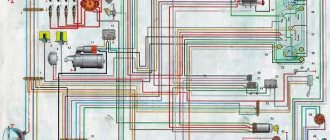
General ignition circuit for older UAZ models
And not only UAZs, but also other domestic cars, for example, the wiring of the Moskvich 2141 and a number of other brands and models are subject to alterations.
Effect of modernization
What is important is that the engine compartment and interior electrical wiring of the UAZ 31514 remains virtually unchanged, and the alteration itself is characterized by the installation of new elements under the hood.
- The engine begins to operate stably in all modes;
- Improves cold starting;
- Fuel consumption is normalized;
- The engine power will reach the passport data.
Differences between ignition systems
The main difference between the two systems is the moment of sparking:
- In classic ignition, a slider under the distributor cover is responsible for this when it comes into contact with the output contact on the spark plug wire. In this case, the supply of a high-voltage pulse occurs with an increase. It seems to be lubricated, reducing the spark power at the spark plug electrodes.
- In contactless ignition, the switch generates a charge and releases it almost instantly upon receiving a signal from the Hall sensor. As a result, the candle produces a more powerful spark. Among domestic off-road vehicles, the Niva has a similar contactless ignition system - see the VAZ 21213 wiring diagram.
The electronic switch is often mounted in UAZ vehicles on the partition on the left side.
Please note! More powerful sparking promotes self-cleaning of the spark plug, because The fuel burns intensively, leaving no deposits.
electrical circuit in its simplest form
How to “light” your car correctly: procedure and nuances of the procedure
The good old UAZ-469 is one of the simplest cars. As if assembled from a children's construction set, it is by no means replete with any frills or bells and whistles. Instead of air conditioning, there is the option to remove the soft roof, and instead of the power package, there is a complete lack of anything that can be controlled using this package. However, there is electrical wiring on this car. Although the same electrical circuit for the UAZ-469 ignition is implemented in the simplest way.
Starter
On a UAZ-469 car, the starter is connected almost directly, through the ignition switch and relay. There is simply no more electronics in the ignition circuit. Even in the more modern Hunter, which not every car enthusiast can distinguish from a UAZ-469 in appearance, the electrical circuit is much more complex. The control pulse from the ignition relay goes directly to the generator, and all wiring goes through the fuse block. The 469 used fuses that only went to the lights and generator. In general, an experienced UAZ-469 owner simply does not need an electrical circuit. You can understand this car in a few minutes.
Peculiarities
It is worth noting several interesting features of this car. which will be of interest to those who get behind the wheel of the legendary UAZ for the first time. For example, the light switch of this car is located at the feet in the form of a special pedal. We won’t judge how convenient it is while driving; we’ll leave it to those who have already driven a UAZ-469. The wiring diagram of this car is also full of many interesting features that are elegant in their simplicity. Oil level and pressure sensors, for example, went directly to the dashboard and emergency indicator, bypassing the fuse box and other elements. This allows you to literally repair your car “on your knees”, from anywhere. It’s not for nothing that the 469th is still valued by the military. When repairing a UAZ-469, they don’t even need an electrical circuit.
Characteristics
Despite its simplicity, the UAZ-469 already in those years had an autonomous heater, two fuel tanks and excellent cross-country ability. It was possible to overcome fords, obstacles and bad roads on this SUV without any modifications, but today tuning of various UAZs, including the 469 model, is becoming increasingly popular. Amateurs equip cars with larger wheels with mud tires, lift the car and install more powerful engines. True, with the latter option, all the simplicity of the design fades into the background, because you have to completely redo the entire electrical wiring of the cars. Nevertheless, the popularity of the car is only growing.
fb.ru
Why turn on the ignition?
To properly configure and adjust the operation of the engine cylinders on the UAZ-469, you must have certain skills. We will talk about them later, but first we suggest you find out for what purposes the contactless ignition should be set correctly and what this can entail. After connecting the key to the ignition switch, multiple components and mechanisms come into play, without which the functionality of the engine would be impossible.
So, why set this parameter:
- The motor will operate optimally and stably in all modes. Otherwise, its operation will be unstable and cause inconvenience for the car enthusiast.
- Cold starting of the power unit will be significantly improved. Naturally, if you want to start the engine without problems in thirty-degree frost, then for this you will also need to fill the engine with the appropriate oil and check the performance of the spark plugs.
- Fuel consumption is normalized, otherwise it may be increased.
- The power of the power unit will be optimal, as noted in the service book (the author of the video is the smotri Vidik channel).
general information
Serial production of the UAZ “Hunter” modification began on November 19, 2003. The predecessors of the car, modifications: 3151, 31512, 31514, 31519, 3153 were produced from 1985 to 2007. The founder who laid down the principles of the all-terrain model, UAZ-469, was produced from 72 to 85. For most fans, the cessation of production of the car in 2014 was unexpected. However, a year later, the creation resumed, only the modification complied with the increased environmental standards of the Euro-5 class.
Electrical diagram of UAZ “Hunter” with fuel injection:
The wiring diagram of the UAZ Hunter is made according to the principle of one conductor, the second being the car body. Electrical circuits that control a power plant with several conductors are connected to the core only through the electronic unit. Communication with other consumers occurs through the ignition switch. The combination switch contains an interaction point and a mechanism that prevents theft. The circuit is safe because the on-board voltage does not exceed twelve volts.
The car console is equipped with devices for opening road lights and anti-fog lights. In addition, there are regulators for the operating mode of the electric fan of the stove. The following are combined into a single unit located on the switches under the steering wheel of the car: headlights, turn lamps, glass cleaners, and a cleaning fluid sprayer. Devices that consume more power are connected via electromagnet relays.
Connection diagram for motor control ZMZ-5143.10:
How the ignition system works
The fuel mixture is ignited as follows:
- The driver turns the key in the lock.
- Current from the battery goes to the starter.
- The crankshaft begins to rotate.
- The distributor turns on.
- Current flows to the coil.
- It passes through the switch to the distributor.
- The last device distributes the current among the spark plugs.
This ensures proper ignition in the engine. However, there are early and late arson. Then we can talk about malfunctions of the power unit.
Early ignition
Early ignition occurs before the cylinder piston approaches top dead center. Gasoline with air and oil is ignited while the piston is still moving. Such problems arise due to an incorrectly set ignition angle.
Experienced mechanics identify such a breakdown by the following signs:
- the power unit does not start immediately;
- unstable operation of the engine when idle at traffic lights, when the car is standing still;
- the appearance of a chattering sound that does not go away when the load increases;
- When disassembling the engine, mechanics discover carbon deposits on the spark plugs. This means that the fuel does not burn out completely;
- increased fuel consumption;
- dark smoke from the muffler pipe.
These are all signs of pre-ignition. Let's look at what happens when the ignition is slow and ignition does not occur on time.
Late ignition
If the marks are set incorrectly on 402 ZMZ engines, late ignition occurs when the piston has already passed the top point. The car owner can notice this by a drop in power with increased gasoline consumption.
Experienced mechanics notice late ignition by the following signs:
- candles turn gray or white;
- the engine begins to heat up very much, although the cooling system is in order;
- The motor may stall when the load increases.
Correct ignition adjustment and adequate placement of marks will help to cope with the problems described above.
Do-it-yourself underwater ignition for UAZ drawings
Well, school is finally over, and it’s time to disappear into the garage. All the parts have been purchased, all that remains is to assemble everything and put it on the car.
Now everything is in order:
I threw out the excess from the distributor
I placed plates (circled in red) so that the bearing would not fly out of the base, otherwise I would have to walk there. b
Next I took plate number 24.
In general, this plate is not necessary, but I installed it to press the leg of the Vacuum Corrector with it
I cut holes in it for the DH fastening nuts
This is what it looks like
I cut the parts for fastening the curtain. In general, I took the old slider from the contact distributor, estimated the height at which the curtain should be and cut off a ring (1) from the slider on which the curtain will rest, and processed the remaining upper part of the slider, fitting everything in place (2)
Well, I installed the whole thing in the distributor. (just in case, I coated all the nuts and bolts with sealant to prevent them from coming loose due to vibration)
I did not embed the plugs into the lid, but simply screwed them on top.
And when yesterday I finally assembled the distributor, practically “holding everything in my hands” I decided to make a test run... It was still an exciting moment of truth... but will it work?! In such a slight tension I got behind the wheel. I turned the ignition key. And voila! Started up! I just stalled at XX, turned the distributor a little, everything is ok! works.
And today I have already secured everything so that I can drive.
I twisted the switches on top of each other, putting a rubber gasket between them. True, I’m wondering if it will melt, so they heat up quite a bit
I screwed them into the cabin, onto the steering column support.
I didn’t want to attach the ignition coils to the valve covers, but I liked the place where the old bobbin was attached.
Well, in general, this is what it looks like under the hood
Don’t scold me for the wiring, as soon as I buy corrugated paper I’ll pack it more carefully)
And naturally I went out to check the new thing. At first there was a failure when I sharply pressed the gas and the car nodded off, I turned the distributor again. The failure is gone, now it’s rushing like a tank :=)
Ps There was a slight hitch with the +12V power supply to the coils. On the old coil I have an additional resistance and it turns out there are 3 terminals on it. 1 - to the capacitor, 2 - VC
and 3 - output B
, I get a wire from the “voltage regulator” and from the “ignition switch”
the VC output
but I get it on the reel itself, and then what?! passes through resistance and goes to the starter from terminal B
. In general, I twisted the wires that went to the VC
and
B
together and connected the “+” wire from the coils to them.
It works, but it’s still interesting, right, no. Tell me who knows!
Underwater ignition for UAZ drawing
Underwater ignition kit for UAZ
This kit includes factory components from the VAZ family. There should be a pair of them: two Hall sensors, a pair of sets of connecting harnesses designed for the Hall sensor, two VAZ 2108 switches, two two-terminal coils.
By the way, all this duality is precisely the only drawback of the system. After all, the more parts in a unit, the less reliable it is. The spare parts themselves are not expensive, you can carry spare parts with you, and you can purchase them at any auto store.
Coil device
Underwater ignition on a jeep
The UAZ 469 ignition coil has a complex design:
- screw-in terminal with high voltage;
- voltage output;
- lid;
- contact spring;
- low voltage clamp;
- gasket for sealing;
- fastening bracket;
- magnetic circuits;
- contact plate;
- primary and secondary winding;
- insulation gaskets;
- frame;
- insulator;
- iron core;
- insulating mass;
- additional resistor and its insulator;
- screw and plate for fastening the resistor.
The distributor performs the function of distributing and interrupting the ignition of the UAZ 469. It has vacuum and centrifugal regulators. The centrifugal changes the ignition angle of the UAZ depending on the frequency with which the crankshaft or camshaft rotates.
BSZ spark plugs are a very important element. With their help, the working mixture in the combustion chamber in the cylinders ignites and gives a good spark so that the car starts quickly. Most often they use A12BS spark plugs, which cannot be disassembled, so in case of a malfunction you need to have new ones in stock that can be quickly and easily replaced.
Wires for high voltage are made from PVL-1 wire. They connect the coil to the distributor, and the distributor to the spark plugs. The spark plugs are attached to the central electrode using special tips with resistors.
electrical circuit in its simplest form
The good old UAZ-469 is one of the simplest cars. As if assembled from a children's construction set, it is by no means replete with any frills or bells and whistles. Instead of air conditioning, there is the ability to remove the soft roof, and instead of power packages, there is a complete absence of anything that can be controlled using this package. However, there is electrical wiring on this car. Although the same electrical circuit for the UAZ-469 ignition is implemented in the simplest way.
Starter
On a UAZ-469 car, the starter is connected almost directly, through the ignition switch and relay. There is simply no more electronics in the ignition circuit. Even in the more modern Hunter, which not every car enthusiast can distinguish from a UAZ-469 in appearance, the electrical circuit is much more complex. The control pulse from the ignition relay goes directly to the generator, and all wiring goes through the fuse block. The 469 used fuses that only went to the lights and generator. In general, an experienced UAZ-469 owner simply does not need an electrical circuit. You can understand this car in a few minutes.
Peculiarities
It is worth noting several interesting features of this car. which will be of interest to those who get behind the wheel of the legendary UAZ for the first time. For example, the light switch of this car is located at the feet in the form of a special pedal. We won’t judge how convenient it is while driving; we’ll leave it to those who have already driven a UAZ-469. The wiring diagram of this car is also full of many interesting features that are elegant in their simplicity. Oil level and pressure sensors, for example, went directly to the dashboard and emergency indicator, bypassing the fuse box and other elements. This allows you to literally repair your car “on your knees”, from anywhere. It’s not for nothing that the 469th is still valued by the military. When repairing a UAZ-469, they don’t even need an electrical circuit.
Characteristics
Despite its simplicity, the UAZ-469 already in those years had an autonomous heater, two fuel tanks and excellent cross-country ability. It was possible to overcome fords, obstacles and bad roads on this SUV without any modifications, but today tuning of various UAZs, including the 469 model, is becoming increasingly popular. Amateurs equip cars with larger wheels with mud tires, lift the car and install more powerful engines. True, with the latter option, all the simplicity of the design fades into the background, because you have to completely redo the entire electrical wiring of the cars. Nevertheless, the popularity of the car is only growing.
What to buy
In fact, you don’t need to buy much, and if you have a working distributor and reel, then the list of purchases will be minimal.
So, you need to buy:
- Hall Sensor;
- High-voltage wires (preferably silicone);
- Switch from VAZ 08.
Advice: If your UAZ is already many years old, then we recommend that in addition to the already indicated list, you buy a new distributor, a coil, and you will also need UAZ 31514 wiring with connectors for the switch.
For reconfiguration and operation, you will also need a new UAZ 31514 wiring diagram, which is shown in the photo below, and which you can print for convenience.
For a new ignition - a new circuit
You can also make your ignition system more powerful by upgrading it with two kits at once:
- Two switches;
- Two Hall sensors;
- Two ignition coils.
Rework
Actually, the work itself comes down to remaking the distributor, which will no longer have a high-voltage part - an electronic switch will generate high-voltage pulses for it . The photos below show the location of two sensors at once.
The sensors are attached to the base and the contact plate has curved edges
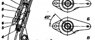
Pay attention to the shape of the contact plate:
- It has curved ends - the sensors are located vertically;
- Flat – the sensors are mounted horizontally.
Flat plate option
Flat plate option
Both options are working, it all depends on the design of the distributor. In the future, you only have to adjust the ignition. The instructions are simple - you must remember that sparking begins when the edge of the plate is in the center of the Hall sensor.
How to install the ignition yourself
You can install the ignition yourself. For such a procedure you will need a standard set of tools. If there is a strobe, then that's good. The tool will allow you to set the correct ignition of the mixture, so as not to endlessly crawl under the hood.
And the procedure is done as follows:
- Warm up the engine to 80 degrees. This is its operating temperature.
- The instrument is connected to the on-board computer.
- The distributor cap lock will need to be unscrewed.
- The signal sensor must be placed on the high-voltage wire of the first cylinder.
- If there is an engine vacuum corrector hose, it must be plugged.
- Light from a strobe light is directed onto the engine crankshaft pulley.
- Start the engine and leave it idling.
- Rotate the distributor body.
- Combine marks.
- Tighten the clamp.
This completes the installation procedure.
A guide to replacing a distributor with an oil pump drive
Before installing a new distributor with a drive, you need to weigh your strengths, since it is not recommended to make mistakes when performing work.
So, how to replace and install the distributor:
- Turn off the ignition and remove the distributor cover; the tips and high-voltage cables are connected to it.
- Then you need to disconnect the wire connected to the switch from the distribution mechanism. You also need to disconnect the pipe connected to the vacuum regulator.
- Taking a 13mm wrench, unscrew the two nuts securing the device and remove the mechanism along with the oil pump drive from the power unit.
- After completing these steps, you will be able to see the gasket located under the drive. If as a result of these actions the position of the crankshaft has not changed, then simply install a new mechanism, making sure that the slider is located opposite the mark. All actions are performed in reverse order. When the installation is completed, the advance angle is adjusted.
- If, as a result, the location of the shaft has changed, then before installation it is necessary to move the piston of cylinder 1 to top dead center. You need to ensure that the marks on the pulley align with the pointer on the motor itself.
Source
Electrical diagram of the UAZ-31512 car | AUTOFIZIK.RU / auto repair
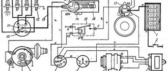
1 — front light; 2 — headlight; 3 — sound signal;
4 — connecting block; 5 — side direction indicator; 6 — additional resistance; 7 — heater switch; 8 — heater fan electric motor; 9 — engine compartment lighting; 10 - generator; 11 — direction indicator relay; 12 — spark plugs; 13 — ignition coil; 14 — starter relay; 15 - starter; 16 — ignition distributor sensor; 17 - switch; 18 — battery; 19 — electric windshield washer; 20 — windshield wiper; 21 — “mass” switch; 22 — portable lamp socket; 23 - emergency vibrator; 24 - fuse block; 25 — oil pressure indicator sensor; 26 — coolant temperature sensor; 27 — coolant overheat warning lamp sensor; 28 — emergency oil pressure warning lamp sensor; 29 — switch for the emergency signal lamp of the hydraulic brake drive; 30 — parking brake warning lamp switch; 31 — brake signal switch; 32 — voltage regulator*; 33 — foot light switch; 34 — parking brake warning lamp; 35 — signal lamp of direction indicators; 36 — warning lamp for emergency condition of the hydraulic brake drive; 37 — horn switch; 38 — carburetor microswitch; 39 — electromagnetic valve of the EPHH system; 40 — block of the EPHH system; 41 — windshield wiper and washer switch; 42 — speedometer; 43 — warning lamp for emergency oil pressure; 44 - warning lamp for coolant overheating; 45 - central light switch; 46 — alarm switch; 47 — fuel level indicator; 48 — coolant temperature indicator; 49 — oil pressure indicator; 50 - ammeter; 51 — signal lamp for high beam headlights; 52 — interior lamp; 53 — interior lamp switch; 54 — direction indicator switch; 55 — fuel level indicator sensor; 56 - thermal (bimetallic) fuse; 57 — fuel tank sensor switch; 58 — ignition switch; 59 — reverse light switch; 60 — rear light; 61 — trailer socket**; 62 — reversing light; 63 — license plate light.
* On vehicles with generator types 665.3701, 161.3771, G700A.30 and 957.3701, an external voltage regulator is not installed.** Installed on some vehicles.
Note. On cars of recent years of production, the ammeter is replaced by a voltmeter, the brake warning light switch is replaced by a low brake fluid level sensor, and the high beam headlight warning light is placed on the dashboard.
How to set it correctly?
After connection, how is the ignition installed for proper engine operation?
What is the procedure and how to correctly set the node settings, read below:
- To begin, the vehicle must be secured in place, and turn on the handbrake. The piston of the first cylinder must be installed at top dead center; note that the hole on the crankshaft pulley must coincide with the mark located on the timing gear cover.
- The cover must be removed from the switchgear. Having done this, you will see a slider located opposite input 1, inside the cover. If it is not there, then the crankshaft must be turned 180 degrees and the octane corrector set to 0. Using a wrench, screw the pointer to the distributor controller body so that it is aligned with the middle mark on the octane corrector. Loosen the screw securing the plastic to the distribution controller housing a little.
- Carefully turn the housing, holding the slider with your finger so that it does not rotate. This way you can eliminate gaps in the drive. The housing is rotated until the sharp part of the petal on the stator is aligned with the red mark on the rotor. Secure the plate with a screw to the controller body.
- The next step will be to install the controller cover in place and diagnose the high-voltage wires. They must be installed in accordance with the order of operation of the cylinders, that is, first, second, fourth, third. When the ignition timing is set, it is necessary to diagnose the correctness while driving.
- Start the power unit and warm it up for about ten minutes until the temperature is about 80 degrees. Moving on a flat and straight road at a speed of approximately 40 km/h, sharply press the gas pedal. If, when accelerating to 60 km/h, you feel or hear detonation, it should be short-lived, then everything has been done correctly. If the detonation is very strong, then the distribution controller must be turned half or one division counterclockwise. In the complete absence of detonation, the set advance angle should be increased, that is, the controller should be turned clockwise.
Site about off-road vehicles, SUVs, off-road vehicles
Malfunctions of the UAZ contactless ignition system manifest themselves in the same way as a conventional contact system, by deviation of engine operation from normal. Do not forget also that failures in the UAZ engine can occur not only due to a faulty contactless ignition system, but also due to problems in the engine power system.
Diagnostics of malfunctions of the contactless ignition system of the UAZ, the engine does not start, stalls after switching off, operates unstably, does not develop full power.
Let us note three important features of troubleshooting the contactless ignition system of the UAZ. Firstly, to check the high-voltage part of the contactless ignition system, you need to make a simple spark gap with a gap of 7-10 mm between the electrodes.
The discharger is necessary in order to prevent the electronics of the non-contact ignition system from breaking down when checking for a spark, which can happen when the gaps between the high-voltage wires and the ground exceed 10 mm.
In addition, if you hold high-voltage wires with your hands, you cannot avoid unpleasant sensations at the moment of spark formation, since the spark energy in the contactless ignition system of the UAZ is approximately one and a half times higher than in the contact one. Before checking, the spark gap should be fixed in a place convenient for work, and the high-voltage wires of the ignition system should be connected to the spark gap electrodes.
Secondly, it is advisable to use a tester to check the circuits of the UAZ contactless ignition system. The use of a test lamp is not recommended. While it can be used to check contact connections and the operability of the switch, diagnosing the distribution sensor using a test lamp is unacceptable. Since its low internal resistance may cause sensor failure.
In most cases, the tester is used in DC voltmeter mode and only when checking the primary winding of the ignition coil and the distributor rotor resistor does the tester switch to ohmmeter mode.
Thirdly, when diagnosing the contactless ignition system of a UAZ, do not touch its elements, and disconnect all wires and elements only when the ignition is turned off. In addition to the devices described, when troubleshooting, you will need a feeler gauge to measure the gaps between the electrodes of the spark plugs.
The UAZ engine does not start.
In UAZ vehicles, the engine may not start due to the following malfunctions of the contactless ignition system:
— Open or short circuit in the primary circuit. — Failures of the distributor sensor, switch or ignition coil — Incorrect connection of wires to the spark plugs. — Contamination or damage to the distributor cap and rotor. — Oiling and contamination of high-voltage wires. — Oily or damaged spark plugs. — Incorrect ignition timing setting.
Find the malfunction using the diagram below. To do this, you will need a tester, a spark plug gap gauge, and a spark gap.
The UAZ engine starts, but after turning off the starter it stalls.
The reason for this is a break in the additional resistor. Malfunctions can be easily eliminated by replacing the resistor or short-circuiting the “+” and “C” terminals of the additional resistor.
The UAZ engine is unstable.
The reasons for unstable operation of the UAZ engine may be:
— Incorrect ignition timing setting. — Damage to high-voltage wires or unreliable connection to the distributor cap. — Malfunction of the rotor noise suppression resistor. — Wear of electrodes or oiling of spark plugs. — Contamination or damage to the distributor cap and rotor. — Broken wires of the sensor-distributor.
A troubleshooting diagram for a non-contact ignition system using a tester, spark gap and probe is shown in the diagram below.
The UAZ engine does not develop full power and does not have sufficient throttle response.
Such engine operation can be caused by incorrect setting of the ignition timing, sticking of the weights of the centrifugal combustion advance regulator and weakening of their springs.