Greetings to all Drayvovites!
As soon as I bought my first KamAZ, I began to look for electrical diagrams for KamAZ. On the Internet I almost immediately found most of the electrical circuits on the website info-kotlas.ru/?page_ >
Thank you very much to this site, but while specific diagrams are quite readable, general diagrams are almost impossible to read. A further search for diagrams on the Internet in good quality only led to a general black and white diagram of the KamAZ Euro 3 Dorestyling Ikar Plus.
By the way, using this diagram, I almost completely replaced the wires in the frame harness of this car, the diagrams and colors of the wires of the pre-Restayl (on the diagrams they write with Elara) and Restayl (Ametek) are generally quite similar, although in some respects they differ.
A search on paper in local stores also did not lead to anything, only black-and-white diagrams of elements, and even mostly non-Eurikov. However, I needed general schemes for Euro 1, Euro 2 and Euro 3 Restyling, so I continued the search and even created 2 topics on Drive: www.drive2.ru/c/521891716412736348/ www.drive2.ru/c/521893090802270999 /
Sadly, I didn’t receive any new diagrams, but I did receive one clear comment from alexkotalex83, revealing the essence of the problem: “it seems like it’s easier to find a diagram for a spaceship than for a Euro Kamaz.”
No, well, I’m not used to giving up, given the upcoming large volume of Kamaz truck wiring, I decided to take a different route - order printed literature with the hope that at least I’ll be lucky there. In general, on the website www.autobukva.ru I ordered several books for a decent amount and one not entirely clear album for 2900 rubles www.autobukva.ru/shop/tru…kamaz/KAMAZ-5320-ELECTRO/
I had a glimmer of hope, but I tried not to rejoice ahead of time, you never know... And now I receive the package and...
PROFIT, these are exactly the same diagrams that were scanned on the 1st site!
Damn, I was surprised at my reaction, but I was very happy. In general, I thought that there were large schemes in at least A2 format, but everything turned out to be simpler: all the schemes are in A3 format, with the exception of the general schemes Euro 2, Euro 3 before and restyling, they are in format ... 1.5 A3 or 3 sheets of A4! Next I wanted to find an A3 scanner, ideally with automatic feed, but it didn’t work out quickly and I decided to scan myself. True, if A3 can still be done on a regular A4 scanner in 2 approaches, then 1.5A3 seems to be impossible, especially on a scanner with auto-feed, like on my Kiosers... In the end, I decided to take a poor Samsung 3180 color MFP at work and... after removing the scanner cover I scanned these non-standard 1.5 A3, and the whole album at the same time... It took several hours, mostly I scanned at 600dpi, which is about a minute on this scanner, and there were more than 150 scans, and there was also the adjustment of those processes...
Consumer power
Power supply to consumers is provided by two batteries and a DC generator. The batteries and the generator are connected in parallel in the circuit. The negative wire from the battery is connected to the car body via a ground switch. It has a remote control and, if necessary, disconnects the battery terminal and the car body.
The on-board power supply voltage is 24 volts. To do this, 2 12-volt batteries are installed, which are connected in series with a jumper. Batteries are necessary to supply electricity to consumers when the internal combustion engine is turned off. After starting the power plant, consumers are powered from a DC generator.
ATTENTION: To prevent fire in the event of a short circuit, the electrical wiring is equipped with a fuse box.
Cummins Engine Protection
A special engine protection option is built into the Cummins engine electronic control unit. Its essence is that several basic engine parameters are continuously compared with their reference range of values.
At the moment when at least one of these parameters goes beyond the reference range, an emergency shutdown of the engine occurs.
The function protects the engine from gradual deterioration of its condition. Many parameters are controlled, of which the main ones are the following:
- coolant level and temperature,
- oil pressure and temperature,
- engine speed temperature in the intake manifold.
You can enable the engine restart blocking setting if one of the main parameters is outside the limits. Using the diagnostic kit, you can program the engine protection function to be turned on or off.
The maximum and minimum calibration values - the reference range - are not programmable via the diagnostic kit. They are “sewn” into the EMC memory by the manufacturer based on engine power.
If the function is enabled, then if any parameter goes beyond the permissible limits, the engine automatically stops. In this case, a fault code is displayed.
In case the vehicle needs to be moved to a safe place, the engine can be restarted.
It will operate at reduced power and this feature cannot be reprogrammed. If at the same time any parameter begins to go beyond the limits, the emergency stop of the engine will work again.
If the function is enabled, the engine does not turn off when the parameters are exceeded. The engine power is automatically reduced and the “WARNING” light comes on. The engine does not turn off within 30 seconds.
If you press a special button during this time, the 30-second interval before shutdown is resumed. Each time you press the button, the interval is resumed and this makes it possible to move the vehicle to a safe place.
Light signaling model 431185
In order to safely use the car and indicate the maneuvers being performed, the manufacturer equipped the model with a light signaling system. Light alarms include:
- Direction indicators;
- Alarm;
- Car brake lights;
- Lamp for reversing vehicle;
- Road train lights.
The blinking of the direction indicator lamps is carried out due to the operation of the breaker relay. The turn signal and hazard warning relays are housed in one housing.
Turning on the direction indicators is carried out using a combination switch located on the steering column of the car. A separate switch is provided to turn on the hazard warning lights.
The brake lights are switched on using a pneumatically driven switch. When you press the brake pedal, compressed air pressure acts on the switch membrane. The membrane closes the contacts for turning on the brake lights.
IMPORTANT: Thanks to the pneumatic drive of the switch, the brake lights come on both in the service brake system mode and when the parking brake is applied.
Trailer lights are used to identify a vehicle and trailer on public roads. The lights are turned on by a switch located on the front panel of the car. You can also read about KamAZ 55111.
Not available:
| № | Part code | Name | Part Information |
| 45104407186690 | Temperature sensor 2872792 | Quantity 1 Note 2872792 Group Winch Subgroup 4510 Serial part number 440 Additionally Not interchangeable with a part previously released under the same number | Not available |
| 65115-4071060 | EMC auxiliary brake harness | Quantity 1 Model 65115 Subgroup 4071 Part number 060 | Not available |
| 4573731679 | Fuse block BPR-13.05 F54.811.000 TU | Quantity 1 Note BPR-13-05 Group Winch Subgroup 4573 Part serial number 731 Additionally Not interchangeable with a part previously released under the same number | Not available |
| 4573733972 | Cruise control switch 581.3710-01.101 | Quantity 1 Note 581.3710-01.101 TU 3 Group Winch Subgroup 4573 Serial part number 733 Additionally Not interchangeable with a part previously released under the same number | Not available |
| 45104370902900 | Diagnostic switch 771.3709-02.100 | Quantity 1 Note 771.3709-02.100 TU 3 Group Winch Subgroup 4510 Serial part number 437 Additionally Not interchangeable with a part previously released under the same number | Not available |
| 6520-4011101-10 | CAN connector bracket | Quantity 1 Model 6520 Subgroup 4011 Part serial number 101 Additionally Not interchangeable with a part previously released under the same number | Not available |
| 6520-4011102-10 | Diagnostic bracket | Quantity 1 Model 6520 Subgroup 4011 Part serial number 102 Additionally Not interchangeable with a part previously released under the same number | Not available |
| 4573748417 | Relay | Quantity 2 Note 903.3747-01 TU 37.00 Winch group Subgroup 4573 Serial part number 748 Additionally Not interchangeable with a part previously released under the same number | Not available |
| 6520-4071100-74 | Engine control system panel harness | Quantity 1 Note panel Model 6520 Subgroup 4071 Part serial number 100 Additionally Not interchangeable with a part previously released under the same number | Not available |
| 6520-4071105 | Intermediate tachograph data bus harness | Quantity 1 Model 6520 Subgroup 4071 Part number 105 | Not available |
| 4575746614 | Diode with protective housing 3403.3747 | Quantity 1 Note 3403.3747 TU 37.003. Group Winch Subgroup 4575 Serial part number 746 Additionally Not interchangeable with a part previously released under the same number | Not available |
| 6520-4071101-24 | Panel Data Bus Harness | Quantity 1 Model 6520 Subgroup 4071 Part serial number 101 Additionally Not interchangeable with a part previously released under the same number | Not available |
| 6520-4071103-24 | Instrument Data Bus Harness | Quantity 1 Model 6520 Subgroup 4071 Part serial number 103 Additionally Not interchangeable with a part previously released under the same number | Not available |
| 45104401100300 | Pedal position sensor | Quantity 1 Note DPP1 Group Winch Subgroup 4510 Serial part number 440 Additionally Not interchangeable with a part previously released under the same number | Not available |
| 45104401100200 | Auxiliary brake release button KGT1 | Quantity 1 Note KGT 1 Group Winch Subgroup 4510 Serial part number 440 Additionally Not interchangeable with a part previously released under the same number | Not available |
| 45104110802890 | Fuel control pedal WM-542 135099 | Quantity 1 Note WM-542 135099 Group Winch Subgroup 4510 Serial part number 411 Additionally Not interchangeable with a part previously released under the same number | Not available |
| 5460-4071031-71 | Engine control harness | Quantity 1 Note motor Model 5460 Subgroup 4071 Serial part number 031 Additionally Not interchangeable with a part previously released under the same number | Not available |
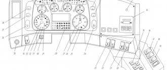
External and internal lighting
External lighting includes headlights and side lights. The exterior lighting is controlled by a combination switch mounted on the steering column.
REFERENCE: External lighting includes the lampshade, the space under the KamAZ 43118 body and the engine compartment lighting lamp.
The KamAZ 43118 electrical circuit includes interior lighting in the form of a lamp installed in the cabin and dashboard lighting. It is possible to adjust the brightness of the backlight.
Cummins Monitored Chains
To monitor the main parameters of the system, the engine electronic system is equipped with sensors that display:
- coolant temperature,
- camshaft position,
- pressure and temperature of fuel, lubricating oil and air in the intake manifold,
- engine speed.
Additionally, the electronic system is equipped with equipment that displays: accelerator pedal position, idle speed check signal, coolant level, vehicle speed, signals from toggle switches for controlling auxiliary functions, and the presence of water in the fuel.
Depending on the type and purpose of the engine, some of the additional signals may not be used.
Glass cleaning and auxiliary heater
The windshield is cleaned by brushes driven by an electric motor.
It has two rotor speeds. The wiper motor is controlled by a combination switch. The windshield wiper system includes an electric washer motor.
To maintain the required temperature in the cabin, KamAZ 431185 is equipped with an autonomous heater. Air circulation through the heating radiator is carried out using an electric fan.
From the above it follows that the KamAZ 43118 color wiring diagram is necessary for performing maintenance and repair of electrical equipment. The machine's wiring consists of several subsystems. The wiring is protected by fuses.
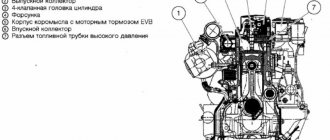
6520-4000010-74 Engine control system. Location by car - KamAZ-6522 (Euro-4):
45104407186690 65115-4071060 1 2 3 4 5 6 7 8 9 10 11 12 13 14 17
List of components from 6520-4000010-74 Engine control system. Location on the vehicle on KamAZ-6522 (Euro-4)
Parts diagrams are for reference purposes only! We do not sell all spare parts from 6520-4000010-74 Engine management system. Location on the vehicle for KamAZ-6522 (Euro-4), presented in this list. If there is a “Show prices” link in the right column, these spare parts are from “6520-4000010-74 Engine management system. Location by car" is on sale. Availability in warehouses for details and prices, see the product card. If there is no “Show cost” link in the right column, we do not sell such parts and do not accept orders for them.
| № | Part code | Name | Part Information | Show all prices |
Cummins Control Unit Programmable Features
The electronic control unit in Cummins engines can be programmed with additional functions or parameters.
Programming is carried out either through a diagnostic kit or by switching toggle switches on the operator control panel. And sometimes both options are possible. The following are the functions available for programming:
- Battery charge monitoring.
- Increasing engine speed at idle.
- Engine speed control and accelerator control, its switching, remote accelerator.
- Cruise control.
- Setting the maximum engine speed and protecting the engine when warming up.
- Brake control (motor or power train retarder) and fan control.
- Protective downshift, engine blocking control and anti-theft function.
- Idle control and J1939 multiplex network control (mux).
- Maintenance control panel (oil change interval management).
- Management of multi-level ECM protection and control of maximum travel speed.
- Power take-off mechanism (engine control at constant speed).
- Power train protection (torque control) and starter interlock.
For detailed information on each function, see the specific engine ECM diagnostic manual.
There are also a number of customizable parameters that are set once by the manufacturer and are changed only in the event of changes in the machine being used. These parameters configure the ECM and its interaction with sensors.