After leaving the water, the functionality of the generator should be maintained.
In this case, the current flows to the lamp, bypassing the switch resistor, and the lamp shines at full heat. G price - from 2 rubles.
A pusher 9 is screwed into the core 8, which abuts the rod 3 of the locking device. KAMAZ disassembling the generator part 3 (checking the chocolate bar)
The core is made of electrical steel plates, insulated from each other with varnish and connected by welding along the outer surface of the package. Technical parameters The GA generator set has a rated voltage of 24 V and a power of W. A pusher 9 is screwed into the core 8, which abuts the rod 3 of the locking device. In this case, you need to replace the block with a new one.
In this case, you need to check the fluid level in the battery banks, and also measure its charge parameter. Therefore, quite a lot of attention was paid to the issue of reliability and maintenance of components and assemblies with your own hands: Wiring KAMAZ external light alarm Electronic interlocks were introduced to prevent electrical circuits from failing.
Start-up and pre-start preparation system The start-up and pre-start preparation system of a KAMAZ vehicle includes an electric start system, an electric torch device and a pre-start heater. The rectifier block and brushes are located in the cover. In this case, the excitation winding of the generator is connected to the power circuit through the emitter-collector junction of transistor VT2.
Correct connection of the generator "KAMAZ" Euro 2. Connect generator "KAMAZ" Euro 2.
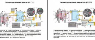
KamAZ generator connection diagram
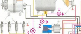
The connection diagram for the KamAZ Euro 3 generator works according to the following principle. The "AM"/"KZ" contacts close when the instrument disconnector and the "VPS" starting device are activated. The ordered movement of active particles from the battery goes to the 60A protection element. Afterwards, it goes to the terminals of the relay that turns off the exciting winding (ROOV), then it comes to the contact spot “W”, which is connected to terminal “B”. Due to the ordered movement of particles, the power transistor VT2 is activated.
Connection diagram for KamAZ 65115 generator:
At the same time, the ordered movement of particles passes through the protective element at 8A and is supplied to section F3 of the mass switch-off relay “RBM”. The contact points of the relay are activated, the ordered movement of particles through the 60A relay reaches the “CL” battery status lamp. The lamp is triggered at the “+D” point and then hits the exciting coil - terminal “Ш” for voltage adjustment, then through transistor VT2 to the housing.
KamAZ-65115:
The exciting coil is connected to the machine's wire network, and the generator is operated in classic mode. When the device produces a portion of the ordered movement of particles, the voltages of the “+D” and “+” terminals have equal values. The result is the disappearance of the current in the initial excitation circuit - the lamp goes out, the coil is powered from the block of auxiliary diodes. An increase in speed stimulates the voltage regulation mechanism to come into effect.
The diagram shows a device in which a relay that opens the exciting winding is used in motors with a torch mechanism. The bottom line is that spark plugs consume a voltage of 19V. Starting the unit and starting to generate electricity by the generator provokes the combustion of the candles. Thus, the relay breaks the battery circuit immediately after the starter is triggered, so that when the unit is active it will not be disconnected from the network. The relay also turns on the primary excitation winding to relieve the contacts of the devices and the starter.
Some machines are equipped with a generator, without including an electrical flare device in the circuit. For example, connection diagram for the KamAZ 5320, 4310 generator.
The light bulb performs a monitoring function; the operation of the product indicates that the process of operation of the initial excitation circuit occurs in normal mode. When the engine starts, the lamp goes out, otherwise the energy-generating device cannot cope with the function.
Connection diagram for KamAZ 4310, 5320 generator:
The diagram shows:
- G – Designation of the mechanism generating the ordered movement of particles;
- GB – Source accumulating electrical energy;
- Q – Starting disconnector;
- C – Electrical circuit component with a capacity of 2.2 µF;
- EL – Indicator lamp 2 W;
- R – Shunt resistance 50 Ohm;
- KV – Voltage regulating device (integral);
- “Ш”, “+”, “W”, “+D” – generator outputs.
| Performance indicators of the KamAZ 4310, 5320 generator | |
| Explanation | Index |
| Voltage, V | 28 |
| Ordered movement of load particles, A | 50 |
| Rotation impulse direction (shaft) | right |
| Safety class | IP-10 |
| Product weight, kg. | 6,2 |
| Adjustment limit, V | 27,8-29,0 |
Connection diagram for the KamAZ 43118 generator:
Designations:
- G – Designation of the mechanism generating the ordered movement of particles;
- GB – Source accumulating electrical energy;
- Q1 – Starter device disconnector;
- Q2 – Excitation coil disconnector;
- C – Electrical circuit component with a capacity of 2.2 µF;
- EL – Indicator lamp 24V, 2 W;
- R – Resistor with a power of at least 2W, 100 Ohm;
- KV – Voltage regulating device;
- “+”, “D”, “W”, “V”, “Sh” – generator terminals.
KamAZ based on chassis 43118-15:
| Characteristics of the KamAZ 43118 generator | |
| Explanation | Index |
| Voltage, V | 28 |
| Ordered movement of load particles, A | 80 |
| Rotation impulse direction (shaft) | right |
| Safety class | IP-1X |
| Product weight, kg. | 6,5 |
| Adjustment limit, V | 27,95-28,85 |
The product is used as a producer of energy for the ordered movement of particles, simultaneously with storage devices. The connection diagram for the KamAZ 43118 generator is similar to the connection diagram for machines running on Euro 2 engines.
Where is the charging relay on KAMAZ
Kamaz repair
Everyday life of a Kamaz operator - The charger has disappeared (replacing the voltage regulator)
3. Charging system - 2
Kamaz 2 repair
KAMAZ disassembling the generator part 3 (checking the chocolate bar)
PT 8114 VZEP for KAMAZ
KamaZ generator operation.
Checking the generator G 288 (g287) KAMAZ, URAL, KRAZ with a built-in relay regulator
Electrical equipment KAMAZ
The principle of operation of the charging relay in the Urals
Also see:
- Brake force valve in KAMAZ
- Winder for KAMAZ 65117 speedometer
- Flywheel retainer KAMAZ 740
- KAMAZ 43118 with kmu and pit drill
- Heat exchanger pipe KAMAZ Euro
- Bel 310 for KAMAZ
- Show KAMAZ on gas
- Technical care KAMAZ video
- KAMAZ brake system energy accumulator
- KAMAZ vs. Ural who is cooler
- KAMAZ and tractor loading earth video
- Water pump KAMAZ 5310
- Cylinder liners KAMAZ 740 30 260
- Spare parts for KAMAZ
- Shank oil seal KAMAZ 65115
Home » Hits » Where is the charging relay on KAMAZ kamaz136.ru
Connection Guide
To successfully connect the generator set, a wiring diagram is required.
Electrical connection diagram
In addition, for proper operation of the installation, you must strictly observe its connection according to the pin diagram:
- the battery and load are connected to the “+” terminal;
- the vehicle ground must be connected to the “-” terminal;
- terminal “B” or “W” is intended to connect to the instrument switch and starter.
- pin “W” or “~” is the phase pin to which the tachometer and the relay blocking the starter are connected;
- output “+D” or “D” from additional diodes for connecting a control light.
Inlet and outlet devices
The communication between the generator and the machine occurs via a network. The outer part of the device is equipped with inlet and outlet connections, the markings of which read:
- “+” — connection point with the positive terminal;
- “-” - connection point with the negative terminal, or the machine body;
- “V” / “W” - connection point with the trigger mechanism and other devices;
- "W" / "
» — connection for turning on the tachometer (43101) and the disconnector blocking the starter;
- “+D” / “D” - connection of the performance monitoring lamp.
It is necessary that the connection diagram for the KamAZ 5511 generator, etc., be followed, otherwise a breakdown is possible.
Device Description
The generator set is one of the main components of a car. It provides power to the vehicle's single-wire electrical circuit while the engine is running. Its design includes a generator and a voltage regulator (the author of the video is yuriy s).
Important Characteristics and design of the KPP-154 gearbox for KamAZ vehicles
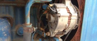
The unit is located at the top of the engine at the front. It is held by 3 paws. Two of them secure the device to the bracket, the third claw serves as a fastener to the tension bar. Powered by . They must have the rated voltage, otherwise the device will not work effectively. Therefore, two belts are installed on KAMAZ vehicles.
Principle of operation
The voltage from the battery is transmitted to the field winding thanks to brushes and slip rings, provided that the instrument switch is turned on and the starter is in position “I” or “II”. A magnetic field arises around it, due to which plus and minus appear on the rotor, corresponding to the south and north poles. When the rotor starts working, the magnetic flux changes simultaneously with it. It crosses the windings of the stator coils, in which alternating current arises and enters the rectifier block. In the block it becomes permanent.
Functions performed
To start the generator set, you need a battery. When the voltage generated during operation of the unit exceeds the battery voltage, the unit will begin to supply power to consumers and charge the battery.
Technical specifications
The G273-A generating set has a rated voltage of 24 V and a power of 800 W. The rated voltage of the G288 generator is 28 V, and the power is 1000 W. The G288 generator is installed on KAMAZ 5320. There are other models of generators.
Device components
KAMAZ generator diagram
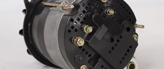
The main elements of the generator are the stator (2) and the rotor (5). In addition, the design includes covers (8), a brush assembly (1) and a rectifier block. The shaft on which the field winding is located rotates on 2 ball bearings. At one end of the shaft there are slip rings that are connected to the winding, at the other there is a fan (6) and a 2-strand pulley (4). The brushes slide along the rings. The rectifier block and brushes are located in the cover.
The voltage regulator is equipped with a seasonal switch. At temperatures below zero degrees, the switch occupies the extreme right position, and at temperatures above zero - the extreme left position.
History of origin
Despite the fact that the new truck is based on the platform of the ZIL 170 model (see in detail about the wiring diagram of the ZIL 130 here), the designers introduced completely new and quite revolutionary technologies, which made it possible to obtain a fundamentally new type of vehicle.
Moreover, KAMAZ 5320 turned out to be very promising for subsequent modifications.
And over the years of production, the following were built on its basis in the factory program:
- Truck tractor;
- Dump truck;
- Truck with an extended flatbed;
- Family of biaxial analogues.
The factory manual contains complete vehicle parameters
For reference: The models of the Kama Automobile Plant for the most part had a similar design, and according to the existing tradition, the main components and assemblies were 80% unified. In particular, the KAMAZ 5320 wiring diagram is used on models 53215, 4325, 4410 and 5511.
Glass cleaning and auxiliary heater
The windshield is cleaned by brushes driven by an electric motor.
It has two rotor speeds. The wiper motor is controlled by a combination switch. The windshield wiper system includes an electric washer motor.
To maintain the required temperature in the cabin, KamAZ 431185 is equipped with an autonomous heater. Air circulation through the heating radiator is carried out using an electric fan.
From the above it follows that the KamAZ 43118 color wiring diagram is necessary for performing maintenance and repair of electrical equipment. The machine's wiring consists of several subsystems. The wiring is protected by fuses.
Scheme ZIL-130
The operation of electrical equipment is checked on special stands or directly on the car.
The simplest ways to check a DC generator without removing it from the car are as follows:
1) at medium engine speed, turn on the headlights. If the ammeter needle is at zero or shows charging, then the generator is working;
2) start the engine; turn on all network lamps; disconnect wires B, W and Z of the relay regulator from the terminals; Connect the ends of these wires together.
Isolate from vehicle ground; Gradually increase the engine speed from idle to medium speed. With a working generator, the current value according to the ammeter readings should increase in accordance with the increase in engine speed. During this test, the current value must not be allowed to exceed that indicated on the ammeter scale. When stopping the engine, you must immediately disconnect the tips of the relay regulator;
Checking generator operation
You can check the functionality of the generator in several ways using certain methods, for example: you can check the output current of the generator, the voltage drop on the wire that connects the current output of the generator to the battery, or check the regulated voltage.
To check, you will need a multimeter, a car battery and a lamp with soldered wires, wires for connecting between the generator and the battery, and you can also take a drill with a suitable head, since you may have to twist the rotor by the nut on the pulley.
Basic check with a light bulb and multimeter
Connection diagram: output terminal (B+) and rotor (D+). The lamp must be connected between the main output of the generator B+ and contact D+. After this, we take the power wires and connect the “minus” to the negative terminal of the battery and to the generator ground, the “plus”, respectively, to the plus of the generator and to the B+ output of the generator. We fix it on a vice and connect it.
“Ground” must be connected very last so as not to short-circuit the battery.
We turn on the tester in DC mode, attach one probe to the battery to “plus”, and the second one too, but to “minus”. Next, if everything is in working order, then the light should light up, the voltage in this case will be 12.4V. Then we take a drill and start turning the generator, accordingly, the light bulb will stop burning at this moment, and the voltage will already be 14.9V. Then we add a load, take an H4 halogen lamp and hang it on the battery terminal, it should light up. Then we connect the drill in the same order and the voltage on the voltmeter will show 13.9V. In passive mode, the battery under the light bulb gives 12.2V, and when we turn it with a drill, it gives 13.9V.
Generator test circuit
Strictly not recommended:
- Check the functionality of the generator by short circuit, that is, “to spark”.
- It is also undesirable to allow the generator to operate without consumers turned on; it is also undesirable to operate with the battery disconnected.
- Connect terminal “30” (in some cases B+) to ground or terminal “67” (in some cases D+).
- Carry out welding work on the car body with the generator and battery wires connected.
KpaHik › Blog › How to check a car alternator
A car generator is the main source of energy in the on-board network, and if there is a problem or failure, you won’t be able to drive for long on one battery, which is why it is so important to monitor the performance of the generator. In most cases, checking a car's generator with your own hands is not difficult, since no matter what car you check on, the principle is the same. But still, many car owners often wonder: how to check a car’s alternator using a multimeter and available tools. How to check the operation of the generator. Sequencing
Generator device
The design of a car generator implies the presence of its own rectifier and control circuit. The generating part of the generator, using a stationary winding (stator), generates three-phase alternating current, which is then rectified by a series of six large diodes and the direct current charges the battery. Alternating current is induced by the rotating magnetic field of the winding (around the field winding or rotor). Next, the current is supplied to the electronic circuit through the brushes and slip rings.
Generator structure: 1.Nut. 2. Washer. 3.Pulley 4.Front cover. 5. Distance ring. 6.Rotor. 7.Stator. 8.Back cover. 9.Casing. 10. Gasket. 11.Protective sleeve. 12. Rectifier unit with capacitor. 13. Brush holder with voltage regulator.
Important DON combines from Rostselmash: review of the best, forage harvester, grain harvester
The generator is located at the front of the car engine and is started using the crankshaft. The connection diagram and operating principle of a car generator are the same for any car. There are, of course, some differences, but they are usually associated with the quality of the manufactured product, the power and the layout of the components in the motor. All modern cars are equipped with alternating current generator sets, which include not only the generator itself, but also a voltage regulator. The regulator equally distributes the current in the excitation winding, and it is due to this that the power of the generator set itself fluctuates at a time when the voltage at the power output terminals remains unchanged.
New cars are most often equipped with an electronic unit on the voltage regulator, so the on-board computer can control the amount of load on the generator set. In turn, on hybrid cars the generator performs the work of the starter-generator; a similar circuit is used in other designs of the stop-start system.
The principle of operation of a car generator
Connection diagram for the VAZ 2110-2115 generator
The alternator connection diagram includes the following components:
- Battery.
- Generator.
- Fuse block.
- Ignition.
- Dashboard.
- Rectifier block and additional diodes.
The principle of operation is quite simple: when you turn on the ignition, the plus goes through the ignition switch through the fuse box, the light bulb, the diode bridge and goes through the resistor to the minus. When the light on the dashboard lights up, then the plus goes to the generator (to the excitation winding), then during the process of starting the engine, the pulley begins to rotate, the armature also rotates, due to electromagnetic induction, electromotive force is generated and alternating current appears.
The most dangerous thing for the generator is the short circuit of the heat sink plates connected to the “ground” and the “+” terminal of the generator by metal objects accidentally falling between them or conductive bridges formed by contamination.
Next, the diode passes plus into the rectifier block through a sine wave into the left arm, and minus into the right arm. Additional diodes on the light bulb cut off the negatives and only positives are obtained, then it goes to the dashboard assembly, and the diode that is there allows only the negative to pass through, as a result the light goes out and the positive then goes through the resistor and goes to the negative.
The principle of operation of a car DC generator can be explained as follows: a small direct current begins to flow through the excitation winding, which is regulated by the control unit and is maintained by it at a level of slightly more than 14 V. Most generators in a car are capable of generating at least 45 amperes. The generator operates at 3000 rpm and above - if you look at the ratio of the size of the fan belts for the pulleys, it will be two or three to one in relation to the engine frequency.
To avoid this, the plates and other parts of the generator rectifier are partially or completely covered with an insulating layer. The heat sinks are combined into a monolithic design of the rectifier unit mainly by mounting plates made of insulating material, reinforced with connecting bars.
Next, let's look at the connection diagram for a car generator using the example of a VAZ-2107 car.
Related Posts
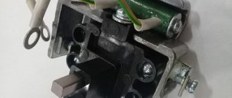
To prevent the batteries from being disconnected from the body of a Kamaz vehicle while the engine is running using a remote ground switch, vehicles have a ground switch lock. When the driver releases the button, under the action of the return spring 7, the core and pusher return to their original position.
Maximum load current, A Gas is released on the surface of the electrolyte in the form of bubbles. The zener diode does not pass current through itself at a voltage below the stabilization voltage and breaks through, i.e.
Spring-loaded contact plates 1 and 2 are attached to rod 3. For diagnostics, you will need a multimeter, which, in fact, is always used to detect faults in the wiring.
Advice: during long-term parking, you should turn off the main switch yourself, since the batteries are discharged through the generator field winding even when the engine is not running. The generator is located in the upper front part of the engine and is attached with two legs to the bracket, and with the third to the tension bar, and is driven into rotation by two V-belts. The generator housing has paw eyes for mounting this unit on the engine, as well as for adjusting the position of the generator and the tension of the drive belt.
Generator connection diagram for VAZ 2107
The VAZ 2107 charging scheme depends on what type of generator is used. To recharge the battery on cars such as VAZ-2107, VAZ-2104, VAZ-2105, which have a carburetor engine, you will need a G-222 type generator or its equivalent with a maximum output current of 55A. In turn, VAZ-2107 cars with an injection engine use a generator 5142.3771 or its prototype, which is called a high-energy generator, with a maximum output current of 80-90A. It is also possible to install more powerful generators with an output current of up to 100A. Absolutely all types of alternating current generators have built-in rectifier units and voltage regulators; they are usually made in the same housing with brushes or are removable and mounted on the housing itself.
The VAZ 2107 charging circuit has minor differences depending on the year of manufacture of the car. The most important difference is the presence or absence of a charge indicator lamp, which is located on the instrument panel, as well as the method of connecting it and the presence or absence of a voltmeter. Such circuits are mainly used on carburetor cars, while on cars with injection engines the circuit does not change, it is identical to those cars that were manufactured previously.
Generator set designations:
- “Plus” of the power rectifier: “+”, V, 30, V+, WAT.
- “Ground”: “-”, D-, 31, B-, M, E, GRD.
- Excitation winding output: Ш, 67, DF, F, EXC, E, FLD.
- Output for connection to the serviceability lamp: D, D+, 61, L, WL, IND.
- Phase output: ~, W, R, STA.
- Output of the stator winding zero point: 0, MP.
- Output of the voltage regulator for connecting it to the on-board network, usually to the “+” of the battery: B, 15, S.
- Voltage regulator output for powering it from the ignition switch: IG.
- Voltage regulator output for connecting it to the on-board computer: FR, F.
Generator circuit VAZ-2107 type 37.3701
- Accumulator battery.
- Generator.
- Voltage regulator.
- Mounting block.
- Ignition switch.
- Voltmeter.
- Battery charge indicator lamp.
When the ignition is turned on, the plus from the lock goes to fuse No. 10, and then goes to the battery charge indicator lamp relay, then goes to the contact and to the coil output. The second terminal of the coil interacts with the central terminal of the starter, where all three windings are connected. If the relay contacts close, then the control lamp lights up. When the engine starts, the generator generates current and an alternating voltage of 7V appears on the windings. Current passes through the relay coil and the armature begins to attract, and the contacts open. Generator No. 15 passes current through fuse No. 9. Similarly, the excitation winding receives power through the brush voltage generator.
Important The best self-propelled and trailed forage harvesters: owner reviews, comparison
Starter blocking circuit when the engine is running
If the engine is running, accidentally turning on the starter is very painful. When turned on, the drive gear (Bendix) tries to engage with the rotating engine flywheel. Impacts on the teeth break them off and the starter shaft and housing may break.
To prevent accidental activation of the starter, a starter blocking relay 11 is provided. This is an electronic circuit consisting of a control part and an output trigger. Before starting the engine, the starter interlock relay receives power from point 11C. Transistor T4 is closed, T5 is open. The starter relay turns on through it and it works.
After starting the engine, an alternating voltage from the generator phase comes to the input of the control part of the starter blocking relay circuit. This AC voltage is a signal to the interlock relay that the engine is running. The trigger turns out to be overturned, transistor T4 opens and closes transistor T5. The starter relay 4 circuit is broken, and if the starter is accidentally turned on, it will not work. The starter can only operate again after the engine has stopped, in which case the alternating voltage is lost from the generator and the starter interlock relay circuit is reset again. Transistor T4 will be buried and open transistor T5, the starter relay circuit 4 will close, and it will turn on the starter. (see Starting the engine)
Relay regulator YA120AT
The G273-A alternating current generator with a rated voltage of 28 V and a power of 800 W was created for MAZ and KamAZ vehicles instead of the G-271, G-272 generators based on the G250 generator. The generator has a built-in rectifier unit BPV4-45 and an integrated voltage regulator YA12OAT. The stator phase windings are connected in a star configuration. The zero point of the “star” is designed to power the excitation winding with a voltage not exceeding 14 V. This made it possible to use a 14-volt generator rotor on the generator and reduce the overvoltage of the voltage regulator elements when the load is shed by approximately half. To facilitate the excitation of the generator, a make-up resistor Rп 75 Ohm is connected between the excitation winding and the “+” terminals of the generator and battery. The current passing through this resistor and the excitation winding does not exceed 0.05 A; this does not lead to a noticeable discharge of the battery when the ground switch and the instrument and starter switch are turned on. A capacitor 9 is connected between terminals “B” and “-” of the generator to reduce radio interference. The integrated voltage regulator Ya120AT of the G273-A generator differs from the Ya112B regulator in the presence of two series-connected zener diodes V5 and V6, the number of resistors and the value of their resistance. The connection diagram for the generator set of a KamAZ vehicle provides for: blocking the remote battery ground switch when the generator is running to protect semiconductor devices from surge voltages; disconnecting the generator excitation winding to prevent burnout of the spark plugs of the electric torch device when starting the engine. The battery ground is turned on by pressing button 5. In this case, current flows into the electromagnet winding of the ground switch through the closed contacts of relay 6 of the heater electric motor. After moving the instrument switch and starter 4 to position 1, voltage is supplied through the “VK” terminal and the closed contacts of the relay 8 for turning off the excitation winding to the voltage divider and the control circuit of the output transistors. In this case, the output composite transistor V2-V1 opens and conducts current from the batteries through the feed resistor Rп into the excitation winding of the generator. At the same time, current flows from the battery into the winding of relay 6, it opens the closed relay contacts and closes the open contacts. Open relay contacts prevent the battery ground from being turned off when the engine is running. The generator sets of MAZ and KamAZ vehicles have a seasonal winter-summer voltage adjustment switch, since their batteries are installed outside. The seasonal adjustment resistor Rpr (0.25-0.5 W, 6.8 kOhm) is connected between terminal “C” and the “ground” of the regulator with a screw located in the IRN casing.
Malfunctions and repairs
Repair of the generator set is necessary in the following cases:
- The ammeter gives readings of the discharge current at minimum crankshaft speed. In this case, it is recommended to adjust the tension of the drive belt, inspect the rings and wipe them with a cloth soaked in kerosene or gasoline. You should also check the height of the brushes. It should not exceed 1 cm.
- Breakdown in the housing of the rectifier unit. In this case, you need to replace the block with a new one.
- If a short circuit occurs in the rotor, the rotor mechanism must be replaced.
- In case of poor contact in the excitation circuit or if the belts slip, you need to clean the brush holder, check their size and condition. You should also inspect the belts and replace them (if damaged).
- Load current fluctuation. It is necessary to clean the brush holder, inspect the spring mechanisms, adjust the belt tension and the mounting of the vehicle's generator set.
- The charging current is too high. In this case, you need to eliminate the short circuit in the circuit or replace the regulator.
- Increased noise level during operation. The pulley nuts should be tightened and the bearing replaced. It is necessary to inspect the entire mechanism and straighten the bent areas.
- Bearing overheating. Inspect the fan belt; if necessary, adjust its tension.
How to check
Checking the generator set:
- Using an ohmmeter, measure the resistance of the excitation winding of the mechanism.
- If the results do not fall within the 5 to 10 ohm range, check the winding for an open.
- Connect one ohmmeter probe to the stator slip ring, and the second to the stator housing. Check the insulation resistance of the generator and rotor mechanism.
- Switch the ohmmeter to diode test mode.
- Connect the positive contact of the measuring device to the central bus.
- Connect the negative terminal to the terminal of the diode being tested.
- Swap the position of the terminals. The indicators should tend to zero.
- Inspect the brushes. They should not protrude from the holder by more than 0.5 cm.
- Connect the positive terminal to the device terminal, and the negative terminal to the terminal ground.
- Connect the control device to the brushes.
- Apply voltage (13 V). At this time, the control device should light up. When the voltage increases to 15 V, the device should go out.
How to replace a belt
If you hear a whistle or extraneous noise during operation, this means that the belt parts need to be replaced; The belt or belts are changed as follows:
- The vehicle is installed on a special platform.
- Stop the engine and allow the engine to cool.
- Disconnect the negative terminal from the battery terminal.
- Using special equipment, the tension in the generator set drive is loosened.
- Loosen the tension of the mounting bolt and remove the worn belt.
- Install new belts.
- Rotate the mounting bolt to set the required tension.
- Tighten all bolts and nuts. The deflection when pressing on a correctly tensioned belt should be in the range from 0.6 to 1 cm.
- Set the required generator drive tension in accordance with the user manual.
- Reinstall the negative terminal from the battery terminal.
- Start the engine and check the operation of the new belts.
How to remove
To carry out this procedure you will need the following tools:
- keys;
- screwdriver;
- special removable equipment.
In order to remove the Euro-3 generator, you need:
- Unscrew the mounting bolts of the brush holder mechanism.
- Remove the brush holder.
- Unscrew the ball bearing cover mounting screws.
- Remove the cover from the side of the contact rings along with the stator.
- Disconnect the phase terminals of the excitation winding from the terminals of the rectifier block.
- Remove the stator.
- Unscrew the nuts securing the pulley and remove it.
- Remove the fan, key and bushing.
- Using specialized equipment, remove the drive side cover along with the ball bearing and fan.
- Remove the generator set from the vehicle.
Speedometer functions
The sensor is primarily connected to the speedometer. For this reason, you need not only to know where the KamAZ speed sensor is located, to carefully monitor its serviceability, but also to take into account the functionality:
- speed measurement and display;
- displaying information about the distance traveled;
- informing about the current time;
- alarm about exceeding the permissible speed;
- measurement of the number of pulses for correct reading of characteristics.
Speed sensors on KamAZ 43118 vehicles and other models must be operational for safe driving, both in the city and on the highways.
One of the most used devices on a Kama car is the KamAZ speedometer, which today can be mechanical or digital. Of course, there are “aces” who practically do not use the speedometer - some due to “great professionalism”, and others due to the absence (breakage) of the device. But fortunately, the number of such drivers is not so large that they refuse to go out on the road - the majority of the driver fraternity are still more responsible and periodically glance at the dial (display), where the speed of the vehicle is indicated.
Although recently more and more drivers prefer to have an electronic KamAZ speedometer installed on their car, the number of adherents of the mechanical version is still large enough to pay some attention to the differences between the devices. And the difference is not in what dial is used - it is not at all uncommon for electronic speedometers to have a classic “circle with an arrow”
Here, the KamAZ speedometer circuit is of greater importance, that is, how information about movement gets to the measuring instruments and is transformed into indicators understandable to the human eye (and mind) - through electronic signals or a flexible drive. The main essence and purpose is the same for both options - to measure the speed of the car by counting the rotation speed. It’s just that in one case the information is taken from the wheels, and in the other from the transmission.
The same speedometer can be used on different cars, and different versions of speedometers can be used on one car, the main thing is not to forget to configure the devices accordingly. The difference in the size of the wheels can play a bad joke on a person who forgot to make sure that the KamAZ speedometer drive is adjusted for a specific car. Likewise, instrument readings can be influenced by the type of final drive used, as well as what sensors are used in the system.
Originals and analogues, price, articles
| Name/serial number | Price in rubles |
| Kamaz-4310 (1322-3771 Pramo) | From 4500 |
| Kamaz, Maz (Rzhev) 1312-3771 Euro 2 (65116, 65111, 65117) | From 4200 |
| GU 6562 (90 A) for 4310, Cummins (6520, 6500) | From 5500 |
| G273 V1 (45 A) ZIT G273V1-3701 | From 4300 |
| G273 V1 (45 A) KAMAZ 5320 | From 4000 |
| G273 V1 (50 A) (Samara) KZATE G273V1 | From 3700 |
| G273 V2 (50 A) (Samara) KZATE G273V2 | From 4200 |
| G288-O (47 A) at 4310 (Samara) | From 5200 |
| GU 6582 (80 A) Euro 3 (65115) | From 6900 |
| GU Euro-1 (80 A) 4001-3771-40 | From 9500 |
| GU Euro-2 (80 A) 4001-3771-53 | From 7500 |
| Belt 5490 (653974-02) Euro 4 (4308) | From 670 – 700 |
| *prices are as of July 2022 |
jorik101 › Blog › How to check a car generator with your own hands
Design of a car generator link 1
Designations of generator terminals, diagrams link 2 How to check the mass flow sensor with your own hands link 3 About how to check a car generator with your own hands
The generator plays a very important role in the car; for the engine it is like a mini power station that supplies the entire on-board network of the car, including battery (battery). A malfunction of the generator will lead to an inevitable complete discharge of the battery, after which the engine of your car will simply stop working, as well as the entire on-board network. As a result, you will have to “light up” your car or look for a new source of energy. It is very important to detect a generator malfunction in time in order to prevent the above scenario. In order to diagnose a generator, you need to have certain skills and tools. In this article I will tell you how to test a generator at home using a multimeter.
Visual inspection
To check the performance of the electric motor, use a standard multimeter. The tester measures the voltage and resistance of the generator components after dismantling the unit from the car. Before removing the equipment from the machine, an inspection is carried out:
The inspection is carried out with the engine running. There should be no extraneous noise, grinding or whistling. The belt tension can be checked with the engine not running in the “old-fashioned” way - press with force. The degree of sagging should be within 0.5-1 cm.