Knocks in the bed (frame)
The connecting rod bolt nuts are loose
Check the condition of the connecting rod bolts, tighten the nuts
The gaps in the bearings of the lower connecting rod heads are large
Adjust the clearance by removing the shims in the connecting rod lower head connector. If the liner is too thin, replace it
Babbitt chipping on liners
Refill or replace liners
The gaps between the connecting rod upper head bushing and the crosshead pin are large
Replace the connecting rod upper head bushing
The connection between the rod and the crosshead body is loose
Tighten and lock the rod lock nut.
There are large gaps between the crosshead shoes and the bed guides
Set the required clearances using spacers; if the babbitt is worn too much, refill it or replace the bed (frame) sleeve.
The crosshead shoe is loose
Secure the shoe and adjust the gap between the bed guides with spacers
Do-it-yourself repair of one- and two-cylinder KamAZ compressors
Many equipment owners perform simple routine repairs of a KamAZ compressor with their own hands. The repair work includes several stages, which are as follows:
- Cleaning parts. The burnt oily liquid inside the cover is removed by sandblasting, the element is polished, and the coolant is removed. Then wipe and polish the working surface of the valve plate
- Boring and honing of the cylinder. When working, take into account the parameters of the thermal gap. If the inner side of the cylinder is worn more than 0.02 mm, an expansion is made for repair boring. In some versions, sleeves are installed.
- Replacing the crankshaft connecting rod bearings and bushings with ones that are suitable in terms of characteristics and parameters
- Replacement of pistons equipped with pins and connecting rod rings. During repairs, special attention is paid to the parameters of the cylinder.
- Replacement and repair of gaskets, intake and exhaust valves, seals. The latter must be covered with fasteners.
The equipment is installed on a special stand and tested for performance. When checking, the technician compares the results obtained with the factory parameters of the compressor.
If overheating of the bearings is detected, extraneous knocking of pistons and valves is heard, or the compressor is running oil, the permissible rate of leaking liquid exceeds the required levels, repair work is resumed, but it is better to go to a service station
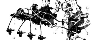
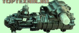
Design and principle of operation
KamAZ trucks are equipped with single- and two-cylinder piston-type units, and rarely with membrane-type units.
The compressor device is presented as follows:
- Connecting rod.
- Piston.
- Cylinder with spacer.
- Rings:
- sealing;
- oil scraper;
- compression
- Sliding bearings.
- Carter.
- Crankshaft,
- Drive gear.
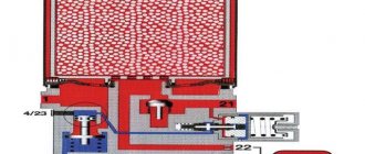
The single-stage compression mechanism is located on the front of the engine flywheel housing. The piston is made of aluminum and has a floating pin secured by thrust rings. Atmospheric air enters the cylinder from the intake manifold of the power plant, which is forced out into the pneumatic system through the discharge valve in the cylinder head.
The liquid is supplied from the engine cooling system and reduces the heating of the cylinder head. Oil flows through the pipelines to the rubbing parts, which lubricates the rear end of the compressor crankshaft and the connecting rod-piston group by splashing.
As soon as the pressure of the pneumatic system reaches 0.8-2 MPa, the pressure regulator is activated and stops the air supply. When the indicator drops to 50 kPa, it closes the outlet, and the compressor pumps air into the system again.
The design and principle of operation are similar to autocompressors for passenger cars, with the only difference being that KamAZ trucks have double protection against short circuits and overheating.
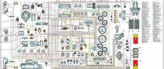
Electronic control systems KAMAZ
Recently, engines from the Kama Automobile Plant began to be classified according to their belonging to one or another environmental class (from Euro-0 to Euro-4). The technical implementation of the Euro-3 class, and then Euro-4, adopted in 2013, turned out to be impossible without the use of electronic engine control systems (ECM). This is what led to the opportunity to perform self-diagnosis of the car using KAMAZ universal error codes.
Ecological class Euro-4
Various configurations of KAMAZ trucks began to be equipped with engines with electronic control units (ECU). And if now the driver is concerned about unhealthy behavior during the operation of famous trucks, symptoms appear in the form of floating speed, loss of traction, unusual noises, increased diesel fuel consumption, self-diagnosis comes to the rescue.
Using information output from the ECU in the form of an error code, it is possible to indicate an accurate electrical diagnosis for KAMAZ. The process of diagnosing and deciphering codes depends on the type of electronic system installed on the truck. Before starting diagnostics, it is suggested to determine the type of ECU based on the installed engine model.
Engine Model Table
Self-Diagnostics No matter what company your V8 is made by, Cummins Inc. (Cummins) or KAMAZ LLC, it is equipped with fuel supply systems from Common Rail and exhaust gas recirculation (EGR) or neutralization systems (SCR), diagnostics will be carried out in accordance with these two types.
The process of self-diagnosis of KAMAZ electronic systems in Euro-3, -4 engines differs slightly from a similar procedure in other vehicles. After pressing a certain button, one of the lamps on the dashboard or indicator unit will begin to blink at different intervals; the number of flashes of the lamp at one interval determines the digit of the code.
Engine with ECU BOSCH MS 6.1
So, let’s get comfortable in the cabin of our KAMAZ, then turn on the ignition with the usual turn of the key. Along with many other indicators, the diagnostic indicator light or “Check Engine”, or in common parlance, a submarine, lights up. The lamp lights up for 3 seconds and goes out, thereby demonstrating its functionality and the serviceability of the ECM. If the lamp does not go out or lights up while the engine is running, a malfunction has been found in the electronic system!
Diagnostic indicator lamp
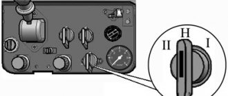
Let's pay attention to the diagnostic mode rocker button (often mounted on the instrument panel on the left, under the steering wheel) or the button for this mode (often located next to the fuse box, under the panel opposite the passenger seat). The “rocker” has two extreme positions for holding and a central fixed position.
Diagnostic mode rocker button
Diagnostic mode button
Lower the rocker to its highest or lowest position and hold it there for more than two seconds. Just press the button and do not release it for the above-mentioned time. After the rocker or button returns back, the diagnostic lamp will flash first in long intervals and then in short ones. The number of long flashes determines the first digit of the error code, the number of short flashes determines the second digit.
Blink Code Alarm Diagram
The diagram shows an example of obtaining code 24. We compare the error code (otherwise blink code, from the English blink - blink) with the table below.
| Error codes for the BOSCH MS6.1 ECU of Euro-3 eco-class engines | ||
| Error code | Description of the malfunction | Operating restrictions set by the ECU |
| 11 | gas pedal | engine speed is limited to 1900 rpm |
| 12, 13 | atmospheric pressure sensor | not limited |
| 14 | clutch sensor | engine speed is limited to 1900 rpm |
| 15 | crankshaft rotation frequency sensor | engine speed is limited to 1600 rpm |
| 16, 17 | Incorrect polarity of frequency rotation sensors; sensors are not installed correctly | engine speed is limited to 1800 rpm |
| 18 | frequency camshaft rotation sensor | engine speed is limited to 1800 rpm |
| 19 | main relay | not limited |
| 21, 22, 24—26 | high pressure fuel pump | engine start failure |
| 23 | inappropriate position of the gas and brake pedals | not limited |
| 27 | poor contact of rack position sensor | engine start failure |
| 28 | brake pedal sensor | not limited |
| 29, 51—53, 81—86, 99 | electronic control unit | engine start failure |
| 31, 32 | air temperature sensor | not limited |
| 33, 34 | air pressure sensor | not limited |
| 35 | cruise control module | not limited |
| 36, 37 | liquid cooling temperature sensor | engine speed is limited to 1900 rpm |
| 38, 39 | fuel temperature sensor | engine speed is limited to 1900 rpm |
| 41 | the signal from the multi-stage input does not correspond to the reference | not limited |
| 42 | maximum engine speed exceeded | The wrong gear may have been selected. Resetting the error when starting the engine again |
| 43 | speed signal error | engine speed is limited to 1500 rpm |
| 54 | excess on-board voltage | not limited |
| 55 | The control unit operation cycle is not completed correctly | not limited |
| 61—67 | CAN line | not limited |
There are often cases when the ECU has recorded several errors; to view the following code, repeat the above steps with the button or rocker. Error codes will be played cyclically. No more than five faults are recorded in the ECU memory. To delete all errors from the control unit’s memory, you must turn on the ignition and hold the “rocker” for five seconds. Thus, you can briefly rid your car of disturbing symptoms in the form of electronic restrictions.
Engine with ECU ISB CM2150
This type of ECU was installed on later KAMAZ models and the diagnostics in this case will differ from the above diagram. After turning on the ignition, the currently active fault is recorded in the memory of the electronic unit; in addition, the fault can be signaled by a red or yellow diagnostic control lamp.
Yellow and red diagnostic indicator lamps
After pressing the “rocker” in any extreme position for more than two seconds, a fault code will be displayed with a half-second interval between flashes of one of the two lamps. The error code digits are separated by a 2-second pause. Unlike the previous type of ECU, the resulting code will be three or four digits!
We compare the error code with the table below. The color of the rows in the table is correlated with the color of the diagnostic control lamp. The red color of the indication indicates the impossibility of starting or continuing driving with this malfunction; the yellow color indicates the need to eliminate the malfunction after finishing driving the vehicle.
| Error codes for ECU ISB CM2150 of Euro-3 eco-class engines | |||||
| 111 | Critical failure inside the engine control module - the intelligent programmable or its component is not working correctly | 422 | Coolant Level - Errors Coming | 689 | Error in the primary engine speed sensor - errors are received |
| 115 | In the engine speed (position) sensor circuit, loss of a pair of signals from the electromagnetic sensor - errors are received | 425 | Engine lubricant temperature - erroneous data received | 1139 | Injector Cylinder #1 - Mechanical system not firing properly or out of adjustment |
| 143 | Low oil pressure - reliable data, but below the optimal operating range | 428 | Water in the fuel sensor circuit - voltage is higher than normal, or the circuit is shorted to a high voltage source | 1141 | Injector Cylinder #2 - Mechanical system not firing correctly or out of adjustment |
| 146 | Coolant temperature is above normal - reliable data, but above the optimal operating range | 429 | Water entering the fuel sensor circuit - the voltage is higher than normal, or the circuit is short-circuited to a low voltage source | 1142 | Injector Cylinder #3 - Mechanical system not firing correctly or out of adjustment |
| 151 | Coolant temperature below normal - reliable data, but above optimal operating range | 431 | Idle Check Circuit, Accelerator Pedal or Lever - Data Received with Errors | 1143 | Injector Cylinder #4 - Mechanical system not firing correctly or out of adjustment |
| 197 | Coolant level - reliable data, but below optimal operating range | 432 | Idle Check Circuit, Accelerator Pedal or Lever - Uncalibrated | 1144 | Injector Cylinder #5 - Mechanical system not firing correctly or out of adjustment |
| 214 | Engine oil temperature - reliable data, but above the optimal operating range | 433 | Intake Manifold Pressure Sensor Circuit - Incorrect Values Coming | 1145 | Injector Cylinder #6 - Mechanical system not firing correctly or out of adjustment |
| 233 | Coolant pressure - reliable data, but below optimal operating range - moderately intense level | 434 | Power failure without turning off the ignition (Ignition Off) - errors are received | 2265 | Starting pump control signal circuit - voltage is higher than normal, or shorted to a high voltage source |
| 234 | High engine speed - reliable data, but above the optimal operating range | 435 | Oil Pressure Sensor Circuit - Errors Coming | 2266 | Start Pump Control Signal Circuit - Voltage Below Normal or Shorted to Low Voltage Source |
| 235 | Coolant deficiency - good data, but below optimal operating range | 441 | Low Battery Voltage #1 - Valid data, but below optimal operating range | 2292 | Fuel metering device - reliable data, but above the optimal operating range |
| 245 | Fan Control Circuit - Voltage Below Normal or Shorted to Low Voltage Source | 442 | Battery #1 High Voltage - Valid data, but above optimal operating range | 2293 | Fuel metering device - flow requirement lower than expected - reliable data, but below optimal operating range |
| 261 | Engine fuel temperature - reliable data, but above optimal operating conditions | 449 | High fuel pressure - reliable data, but above the optimal operating range | 2377 | Fan Control Circuit - Voltage High or Shorted to High Voltage |
| 275 | Fuel Injection Element (Front) - Mechanical system does not operate correctly or is not adjusted | 595 | Turbocharger #1 high speed - reliable data, but above optimal operating range | 2555 | Intake air heater circuit No. 1 - voltage is higher than normal, or shorted to a high voltage source |
| 281 | Solenoid Controlled High Pressure Fuel No. 1 Valve - Mechanical System Not Actuating Correctly or Out of Adjustment | 596 | Electrical charging system voltage high - reliable data, but above optimal operating range | 2556 | Intake air heater circuit No. 1 - voltage below normal, or shorted to a low voltage source |
| 351 | The injector power supply is a faulty intelligent programmable device or component. | 598 | Electrical charging system voltage low - reliable data, but below optimal operating range | 2558 | Auxiliary PWM (Pulse Width Modulation) Trigger #1 - Voltage Below Normal or Circuit Shorted to Low Voltage Source |
| 415 | Low oil pressure - reliable data, but below optimal operating range | 687 | Low speed of turbocharger No. 1 - reliable data, but below the optimal operating range | 2973 | Intake Manifold Pressure Sensor Circuit - Incorrect Data Received |
If you do not find your engine brand or error code for the ISB CM2150 ECU in the table, be sure to write to us and we will immediately try to help.
Malfunctions
During operation, it is necessary to monitor the technical condition of the mechanism, lubrication and the flow of coolant. It is recommended to use only the oil that is specified in the power plant data sheet. Lubrication with contaminated oil is prohibited.
The compressor does not require daily or special technical inspections, but the drive and fastening reliability are checked periodically once every 8-10 thousand km.
During operation, breakdowns of unit parts may occur; they are repaired immediately. Those that are faulty must be replaced.