The Common Rail (CR) fuel supply system allows for a wider range of fuel injection requirements, namely:
- increased injection pressure;
- variable injection start point;
- providing pre- and post-injection;
- regulation of injection pressure depending on the operating conditions of the KamAZ engine and the vehicle.
The Common Rail fuel supply system contains:
- electronic control unit;
- sensors (see Fig. Installation of sensors on an engine with a Common Rail fuel supply system):
- fuel pressure sensor in the high pressure fuel accumulator (“Rail”);
- camshaft position sensor;
- fuel temperature and pressure sensor;
- oil temperature and pressure sensor;
- coolant temperature sensor;
- charge air temperature and pressure sensor;
- crankshaft position sensor;
- an injector with a high-speed solenoid valve that regulates the fuel injection process in each cylinder;
- high pressure fuel pump (HPF) with a fuel flow regulator and a fuel priming pump.
- auxiliary brake system button. On vehicles with KAMAZ engines with a Common Rail fuel supply system, the auxiliary braking system is activated when driving at a speed of at least 30 km/h.
- cruise control/speed limit switch;
- engine diagnostic mode switch;
- engine diagnostic warning lamp;
- fuel pedal;
- brake pedal sensor;
- parking brake sensor;
- engine emergency stop valve;
- clutch pedal sensor.
Installation of sensors on an engine with a Common Rail fuel supply system 1 - injection pump; 2 - electronic control unit; 3 - injector; 4 - high pressure fuel accumulator; 5 — fuel pressure sensor in the high-pressure fuel accumulator; 6 - camshaft position sensor; 7 — fuel temperature and pressure sensor; 8 - temperature and oil pressure sensor; 9 — coolant temperature sensor; 10 — charge air temperature and pressure sensor; 11 — crankshaft position sensor; 12 — engine control system harness; 13 — power control system harness
System diagram and details
High pressure 230-1800 bar.
Pressure in the return line of the injectors, 10 bar.
Pressure in the pressure line, Pressure in the return line.
1. Fuel booster pump. Performs constant pumping of fuel into the pressure line.
2. Fuel filter with preheating valve. The preheating valve prevents the filter from clogging with crystallizing paraffins at low ambient temperatures.
3. Additional fuel pump. Supplies fuel from the pressure line to the fuel pump.
4. Strainer . Protects the high pressure pump from foreign particles.
5. Fuel temperature sensor . Measures the current fuel temperature.
6. High pressure pump (HP pump). Creates the pressure necessary for the operation of the injection system.
7. Fuel metering valve. Regulates the amount of fuel that needs to be supplied to the high pressure accumulator.
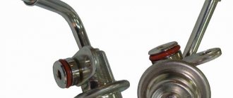
8. Fuel pressure regulator . Regulates fuel pressure in the high pressure line.
9. Pressure accumulator (fuel rail). Accumulates the fuel required for injection into all cylinders under high pressure.
10. Fuel pressure sensor . Measures the current fuel pressure in the high pressure line.
Injector repair kit.
Already in the mode of cranking the crankshaft with the starter, the injection pump creates a starting pressure of 350–400 bar. At minimum idle speed - up to 500-600 bar, and at maximum load - up to 1300-1500 bar. There are pumps with pressure up to 2000 bar. Its value is set by a regulator located on the fuel injection pump housing or on the ramp and subordinate to the electronic engine control unit. When issuing commands, the ECU relies on signals from the rail pressure sensor.
Fuel is supplied through high-pressure pipes to the injectors, which open under the influence of an electrical signal. There are two design options - electromagnetic or with a piezoelectric element. The first one was not particularly fast at first, which forced the designers to look for an alternative. In a piezo injector, voltage is applied to a piezo crystal, which instantly expands. The spool compresses the spring, the injector needle opens the way for fuel - and it is injected into the combustion chamber. However, designers continue to improve electromagnetic devices - both options work successfully on modern engines.
WE DIAGNOSE
There is a minimum of equipment without which it is unreasonable to start working. Diagnostics of electronic systems begins with reading fault codes, checking sensors and actuators. There are no special diesel scanners, there are universal ones, that is, for a wide range of cars, or dealer ones - for a specific brand. To study the signal from the device under test, you need an oscilloscope. But it is expensive; it is more profitable to buy a scanner with an additional oscilloscope function.
Fuel pressure is checked with pressure gauges. Low - mechanical, with a scale of up to 10 bar, and high - with a special device with adapters and a range of at least 2000 bar. And to measure the amount of fuel drained from the injectors, you need your own set.
The troubleshooting algorithm depends on the nature of the failure. If the engine does not start (electronic locks and forgotten secrets do not count), we check the integrity of the timing drive. If the starter rotates the crankshaft with force, this is not bad for the owner, but if without resistance, the repairmen will be happy: the work ahead will be expensive. After all, diesel engines are “plug-in” - when the timing drive is destroyed, the pistons bend the valves, and then whatever happens.
Signs of early ignition
Early injection point
- this is when the piston has not yet reached top dead center, but the fuel has already begun to flow, the explosion goes towards the piston.
In engine operation, this is determined by the following signs: a)
The engine runs harshly.
b)
With a sudden change of gas or under load, a ringing sound is heard, as if from valves, and the higher the engine temperature, the stronger the ringing.
d)
If very early, white smoke is possible.
d)
Poor traction.
e)
High consumption. As a rule, the moment set according to the factory marks is a little late. And so let’s say we realized that the ignition is later and we need to set it earlier, what should we do, where should we turn it? The torque is set at engine operating temperature, but if signs of improper operation are clearly visible even when cold, then adjustment can already begin. We set the drive so that the mark is on top (you can make your own) and release the two bolts at 17. Now you need to understand that the engine remains in place, and the injection pump coupling rotates. Previously, move the injection pump drive in the direction of travel, i.e. clockwise. Later, move the injection pump drive in the opposite direction of movement, counterclockwise. And the most important. You need to move the drive a little at a time, about the thickness of a match from the mark. And be sure to tighten the bolts. Then we start the engine and check its operation; if there are no changes or the machine’s performance is still not satisfactory, you can repeat it and move it a little more. This must be repeated until a slight ringing appears during sharp throttle or load, then you can move back a little and the ringing will disappear, this will be that very moment. The main thing is to move towards something, focusing on something and not too much at once, so as not to get confused. Correctly set injection timing provides the best traction with the lowest fuel consumption, and these are very important indicators in the operation of any machine.
Source
Stand for testing injectors and high pressure pumps.
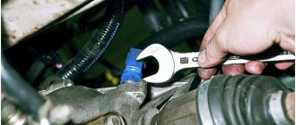
If the timing drive is in order, we proceed to checking the fuel supply. The electric booster pump comes into operation with the turn of the key. When this pump wears out or is damaged, the power it consumes changes; the ECU records this as a malfunction and records its code in the system memory. But you shouldn’t rely completely on electronics, so we connect the pressure gauge to the low pressure line. (For ease of control, the mechanical booster pump has a fitting.) If the pressure here is normal, we move on to the injection pump.
Let's check the fuel pressure in the rail while cranking the crankshaft with the starter. This part of the system is equipped with a fuel pressure sensor, so we will use its services. We connect the scanner to the diagnostic connector and find the desired parameter. If it is below normal, we look for where the fault is hidden. The culprits may be injectors, solenoid valves (regulators) and the fuel injection pump itself.
Diagram of the common rail diesel power system:
Principle of operation
Compressed air from the compressor through terminal 1 of the regulator, filter 3, channel D and check valve 10 flows to terminal 111 and then into the air cylinders of the pneumatic drive. At the same time, through channel G, compressed air passes through cavity B under the balancing piston 9, which is acted upon by spring b. The outlet valve 4, connecting the cavity E above the unloading piston 12 with the environment through the outlet P, is open. The inlet valve 11, through which compressed air is supplied from the annular channel into the cavity E, is closed under the action of its spring in the same way as the unloading valve 2.
scheme
This state of the regulator corresponds to filling the air cylinders with compressed air from the compressor. When a certain pressure is reached in cavity B, the piston 9, overcoming the force of the spring 6, rises upward. Valve 4 closes under the action of the pusher, inlet valve 11 opens, and compressed air from the annular channel enters cavity E.
Under the influence of compressed Air, the unloading piston 12 moves down, the unloading valve 2 opens, and the compressed air from the compressor through outlet 4 exits into the environment along with the condensate accumulated in the cavity. In this case, the pressure in the annular channel drops and the check valve 10 closes. As a result, the compressor operates in unload mode without backpressure.
system pressure adjustment
When the pressure in port 3 and cavity B drops to a certain value, piston 9 moves downward under the action of spring b, Inlet valve 11 closes, and outlet valve 4 opens, communicating cavity B with the environment through pin 11. Unloading piston 12 rises upward under the action of a spring , valve 2 closes under the action of its spring, and the compressor again pumps compressed air into the cylinders.
Unloader valve 2 also functions as a safety valve. If the regulator does not operate at a pressure of 0.8 MPa (8.0 KGS/SMZ}, then at a pressure of 1.0 1.35 MPa (10 13.5 kgf/cm?) the valve will open, overcoming the resistance of its spring and the piston spring 12 The opening pressure of valve 2 is adjusted by changing the number of washers under the spring.
terminal for tire inflation
The pressure regulator has an air bleed valve , for example, for inflating tires, closed by cap 15. When screwing on the hose fitting for inflating tires, the valve is recessed, allowing access to compressed air into the hose and blocking the passage of compressed air to terminal 11. Before inflating tires, the pressure in the air cylinders should be lowered to the pressure corresponding to the activation of the regulator, since during the unloading mode of the compressor operation, air sampling is impossible.
Regulator malfunctions
The main malfunctions of the regulator are wear of rubber seals, cuffs, and rings.
regulator filter
WE REPAIR
Restoring the pump's functionality can only be done by a specialized workshop with qualified personnel and diagnostic equipment. The cost of repairs is from 7 thousand rubles, then it depends on the complexity. In case of some damage, it is wiser to buy a new injection pump. The usual price, about 30 thousand rubles, will shock the tight-fisted diesel operator, which is why repaired or restored products are in use.
A CR diesel with high mileage is often impossible to start due to a malfunction of at least one of the injectors. Fuel leakage through its valve does not allow the pressure in the rail to rise to starting values. There is a special diagnostic kit to check the pressure at start-up. It includes a control pressure gauge, a pressure sensor, connection tubes, plugs instead of actuators and backflow measuring containers.
Disassembly procedure
- Unscrew the screws securing the rear cover of the speed controller and remove the cover assembled with the low-pressure pump;
- remove the automatic fuel injection advance clutch using tool I-801.16.000. First, unscrew nut 2 (Fig. a) securing the coupling. To do this, insert screwdriver 4 into the groove of the nut and, holding clutch 1 from rotating, use wrench 3 to unscrew the nut. Then, screwing puller 5 into the coupling (Fig. b), remove the coupling;
- unseal and unscrew the screws securing the protective casings of the injection pump sections and remove the casing;
- Unseal and unscrew the bolts securing the top cover of the regulator and remove the cover;
- take out the axis of the regulator lever and remove the regulator lever with the weight clutch lever, clutch, regulator spring and spring lever;
- remove the retaining ring and weight holder assembly;
- unscrew the rack plugs, remove the rack bushings, then the racks themselves, having previously unlatched them;
- unscrew the nuts securing the injection pump sections, remove the lock washers of the section fittings and remove the injection pump sections and plunger pushers;
- unscrew and unscrew the nuts and, using a puller I-801.26.000, remove the eccentric of the low-pressure pump drive, the drive gear of the regulator and the intermediate gear;
- remove the second bearing from the idler gear axis;
- knock out the keys from the toe and shank of the cam shaft, remove the rear bearing cover, remove the cam shaft assembly with bearings and remove the front bearing cover;
- using the puller I-801.30.000, remove the bearings from the cam shaft;
- Disassemble the fuel injection pump sections and the low-pressure fuel priming pump using tool I-801.20.000. To press out the discharge valve of the fuel injection pump section, use tool I-801.21.000.
A cutaway view of a high-pressure fuel injection pump with a plunger section shut-off valve.
It is reasonable to replace worn out injectors as a set. The price range is very wide: depending on the model and manufacturer, they cost from 8 thousand to 25 thousand rubles. a piece. The characteristics of each new injector must be recorded in the memory of the engine control unit, because no two injectors have the same performance. Different ones not only have a bad effect on the uniformity of engine operation and its dynamic loads, but also worsen the characteristics of the car. Although each ECU has dynamic adaptation (constant adjustment of the cyclic fuel supply for smooth engine operation), you need to remember that it cannot replace the coding if, for example, you forgot to write it down.
The problem of difficult starting of a diesel engine is one of the most common. And the owner is sometimes dissatisfied, for example, with reduced engine power or exhaust smoke. These problems are the most complex, because they require an assessment of the accuracy of measuring air flow or supercharging operation, the efficiency of recirculation, the exhaust gas system, including the diesel particulate filter (DPF) and the converter. However, these technologies are now well mastered by diagnostic masters.
How to remove the injection pump
- disconnect the manual control cables for the engine stop lever and the governor control lever,
- remove the fuel control rod,
- disconnect all fuel supply pipelines to the pump, outlet and drainage pipelines and the pipeline from the fine fuel filter,
- disconnect the oil supply pipe to the pump and the oil outlet pipe,
- unscrew the coupling bolt of the front flange of the driving half-clutch and the two bolts of the driven half-clutch (in order to unscrew the bolts conveniently, you need to turn the crankshaft through the clutch housing hatch),
- disconnect the spark plug fuel lines,
- remove the high pressure fuel lines,
- disconnect the tube that supplies air to the auxiliary brake working cylinder,
- unscrew the four bolts that secure the injection pump,
- remove the pump itself.