How much does the Zila cabin weigh?
Weight distribution when fully loaded: 2626 kg - on the front axle, 7900 kg - on the rear axle, for an unloaded vehicle: 2120 kg - on the front axle, 2180 kg - on the rear axle.
Interesting materials:
What is a sentry and to whom does he report? What is ID and where can I get it? What is conflict and why does it arise? What are organic substances and where are they formed? What are waste heaps and who is to blame for their occurrence? Why and by whom was the Jesuit order created? Who is the 36 hour work week for? Who is characterized by a mixed body cavity? Where is the +- on the battery? Where is March 8th a day off?
General overview
This vehicle is represented by a Russian-made vehicle from the USSR era, and is also a high-cross-country cargo vehicle created by the Likhachev plant in Moscow. It is considered a successor to the ZIL-157, which was mainly produced for the Armed Forces.
Its first release occurred in the 66th year and continued until the 86th year, and then a more improved version appeared, with an engine running on both gasoline (131N) and diesel fuel (131N1 and 131N2).
Through extensive testing, it was possible to improve the vehicle's performance as well as operational capabilities. The result of testing was an increase in travel and load lift due to the frame design. The engine gained more power, and the driver's area along with the cabin began to meet the signs of ergonomics.
All the innovations made for trucks in the 60s were not received with enthusiasm, and this kind of did not affect its production in any way. But already in 1986, a more powerful truck rolled off the assembly line, its performance characteristics noticeably changing. Losses have dropped to a minimum.
The ZIL-131 car came mainly with a winch, but on some of the models it was missing. Also, all cars were distributed according to factory recommendations. For example, their use in harsh winter conditions. In addition, manufacturing the chassis took a lot of time. After all, a large amount of specialized equipment was mounted on this structural element. Fuel and oil tankers, as well as tank trucks and much more were manufactured on the basis of the ZIL-131 chassis. For military purposes, van-type bodies (kungs) were designed, which housed metalworking rooms and medical stations.
The production of ZIL-131 N ended in Moscow in 1994, due to the fact that production of ZIL-4334 began, and at the Urals engine plant it was carried out until 2002, until it was replaced by ZIL-433420. In addition, at the same time, the ZIL-131 N prototype of the AMUR-521320 brand, as well as units running on diesel fuel, came out of production.
Where is the ZIL-131 engine number located?
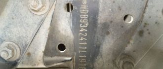
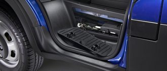
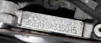
The brand itself, chassis and engine numbers are located in a summary data table, according to factory standards. The ZIL-131 engine number is located on it, and it is attached to the right side on the seat base for passengers. Contains special designations of the XTZ type, which have information about the manufacturer in the abbreviation. X is the designation of the territorial zone, T is the state, and Z is the manufacturing plant. This is followed by 6 digits that indicate the vehicle model. In addition, the chassis number is embossed in the rear of the right side member of the car frame, and the engine number is on the area on top of the front area of the engine block, near the eye bolt. There is also the type of engine and its year of manufacture.
Today, many car owners are wondering where the engine number is on the ZIL-131. Some say that it is located on the cylinder block, while others say it is located under the compressor, or where the mounting ear is screwed in. It all depends on the manufacturer and year of manufacture. If in the case of a compressor, then you should wipe under it with a rag, and everything will be visible. When placing the engine number under the mounting ear, it is usually difficult to see as it will be partially blocked by the top spider (top plate). But regarding the frame number, there are some nuances there too. It is usually located on the right rear side member at the top. If there is a kung, then it can usually be seen under the right battery box. In order to see it, you need a mirror.
In general, the ZIL-131 car turned out to be a successful car in many ways. It had acceptable carrying capacity and maneuverability. It was considered relatively reliable and easy to maintain. Its disadvantage was the engine, due to the fact that it consumed a large amount of fuel. Thanks to this, the diesel ZIL-131 M was subsequently born.
Main advantages of ZIL-131
This vehicle was designed to conquer areas where there are no roads, and therefore it is equipped with a V-shaped eight-cylinder engine, the power of which reaches one hundred and fifty hp, and also has power steering.
The front axle can be turned on using an electric and pneumatic drive, the button of which is located on the dashboard. When the downshift lever in the transfer case is switched from the switch installed in the mechanism, the pneumatic drive for engaging the front axle is forcibly turned on.
In order to avoid knocking out a gear when braking with the engine, moving downhill, the ZIL-131 manual transmission has special locks in second and fourth gear.
The main advantage of the car is the introduction of contactless ignition and an electronic switch.
After startup, the entire electrical circuit is powered by alternating current generated by a powerful generating device. Thanks to experienced engineers, they were able to implement a special emergency pulse generating device into the car, which is used when the electronics-based switch fails.
ZIL-130 car frame and its structure
CONTENT
1 Car frame
2 Frame number ZIL-130
3 Vehicle markings
4 Frame repair
5 Repair of towing device
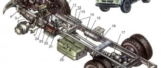
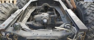
The frame of the ZIL-433360 car is riveted, made of stamped parts, and consists of two spars of variable channel cross-section, connected by cross members. Frame extensions and a buffer are installed in the front part of the frame (Fig. 6-1).
Frame ZIL-130
A towing device with a rubber buffer providing double-sided shock absorption and a hook with a latch for connecting to the trailer's coupling loop is mounted in the hole in the rear cross member of the frame. A towing loop is installed on the chassis of the ZIL-494560 dump truck.
Frame number ZIL-130
Before 1991, the frame number was stamped with paint. After 91, numbers were stamped on the frame with iron padding, at the end of the frame or in front of the cabin, on the right side of the spar. Inspectors are well aware of this; their goal is to recycle all old cars. Now they are not bothering us, but as soon as it comes to registration, problems will immediately arise with registering the car. They know each model, what year and where the frame number is printed; they are taught this. You can do something with the number you painted with paint.
frame paint number
Find the place where it was applied, at least one number. Look what the font was. Type the same font on the computer, cut out a stencil with your number and apply it to the same place using white spray paint. Our task is to make it as close as possible to the factory original and the inspectors will have no questions for you. Over time, the paint will fade and look like the serial number.
ZIL frame number stuffed ZIL frame
VEHICLE MARKING
in the summary data plate, which is mounted in the cab on the right, on the passenger seat base (Fig. 114). The letters ХТ2 at the beginning of the identification number indicate in encoded form data about the manufacturer: X - geographical area of the country; T - country; 2—manufacturer. The next six digits indicate the car model, followed by the chassis and engine number.
The Latin letter in front of the chassis number indicates the encoded year of manufacture of the vehicle.
In addition, the chassis number is painted on the right side member of the car frame, and the engine number (Fig. 115) is stamped on the upper front part of the engine cylinder block (middle line) on a horizontal area near the eye bolt. The engine model number (top line) and the year of its manufacture (bottom line) are also stamped there.
ZIL car marking
Frame repair
When repairing frames, it is necessary to check the tightness of the rivet joints, the presence of cracks in the flanges of the side members and cross members, as well as possible deflection and skew of the side members. Below are recommendations for correcting faults found on frames.
Rivet joints are checked by tapping with a hammer. Loose (rattling) rivets should be replaced. Tightening loose rivets has no effect. Worn holes should be drilled to accommodate the increased diameter of the rivet. If the holes for the rivets are heavily worn (more than 15% of the nominal diameter), the holes can be welded and re-drilled, and then strengthened by running a conical punch through them.
The rivets must fit tightly into their holes. If there is a displacement of the mating parts or if the diameter of the holes in them is different, the holes should be drilled or reamed. The mating parts of the frame must be pressed tightly against each other, since the presence of a gap will allow the body of the rivet being pressed to fill this gap, forming a so-called “blind” washer. If there are difficulties, you should eliminate the gap, using the hole located nearby, tighten the mating parts with a bolt and nut or clamps, and only then carry out riveting.
Frame drawing
ZIL-130 frame drawing
In garage conditions, it is recommended to use hot riveting, that is, heating the rivets in electric or other heating ovens. After cooling, a hot rivet will tighten the mating parts even more tightly. At auto repair plants, preference should be given to hydroriveting using cold rivets. In order not to violate the established position of the parts, replacement of rivets should be done sequentially, that is, first cut off one rivet, install a new one in its place, then cut off the next one, etc.
After riveting, the rivet heads must be correctly positioned (along the axis of the rivet), fully compressed and must have a geometrically correct shape without distortions, sagging or cracks. The diameter of the newly formed rivet head must be at least 1.5 times the diameter of the rod. Riveted joints must ensure a tight fit of the surfaces of the parts being connected over a diameter equal to two diameters of the rivet rod. It is possible to replace the cut rivet with a bolt with a spring washer and a nut.
Deflections and distortions. Determined by inspection, as well as checking using rulers and templates. The curvature of the side members in the plane of the vertical wall should not exceed 2 mm over a wild 1000 mm or 5 mm over the entire length of the spar. Bent frame parts are straightened in a cold state.
Mutual displacement of the frame side members, causing non-perpendicularity of the cross members with respect to the side members, is not allowed. The longitudinal displacement of the side members can be checked by measuring the distance between two cross-lying holes for the engine mounting bolts. A skewed frame should be re-riveted and bent parts replaced.
ZIL-130 frame dimensions
ZIL-130 frame dimensions
Cracks. If cracks are found on the shock absorber spring mounting brackets. These parts should be replaced. If there are cracks on the frame side members, it is necessary to determine the boundaries of the cracks. To do this, it is recommended to thoroughly clean the crack to a metallic shine, rinse with kerosene, wipe dry and tap with a hammer. If there is a crack, kerosene will come out.
At the end of the crack or 5...8 mm away from it, you should mark it with a core and drill a through hole with a diameter of 5 mm along the core. Use a chisel or an emery wheel to divide the groove at an angle of 90° along the crack for welding to a depth of 3 mm on both sides. Fill the crack on both sides, starting from the drilled hole and ending at the end of the crack. Cutting for welding can be replaced by sawing the defective frame part with a hacksaw along the crack to its entire length.
When repairing frame parts, manual electric arc welding with high-quality electrodes or semi-automatic welding in a protective environment should be used. Welding work must be carried out by a highly qualified welder. To weld cracks in frame parts, according to NIIAT, it is recommended to use OZS-b, VN-48 and UONI 13/55 electrodes.
The weld deposit should not rise above the surface of the part by more than 2 mm. In the welding zone, as a result of thermal influence, the fatigue strength of the metal decreases. Strengthening this zone can be done by peening using a pneumatic or plumbing hammer. Any cracks in the side members and cross members can be repaired by welding and installing reinforcing linings (Fig. 6-2).
Types of reinforcement pads
The overlay must be tightly fitted to the configuration of the part being reinforced and connected to the part with rivets or bolts. Welding of reinforcing linings in all cases should be done only with longitudinal seams. When installing reinforcing linings, you should not create excessive rigidity of the assembly at the site of cracks, as this causes the appearance of new cracks at the ends of the reinforcing linings. The material of the reinforcing linings can be steel 3, steel 0.8 or steel 20 with a thickness of 5 mm.
If cracks appear on the lower flange of the frame side members in the area where the cross member is connected to the side member, it is necessary to carry out the following operations to restore the frame: make a reinforcing lining 3
Spar reinforcement
Spar reinforcement:
1 — crack of the frame spar; 2 - drilled hole
end of the crack; 3 — overlay; 4 - bolt; 5 - rivet
weld the cracks on the spar and on the cross member, having previously cut the edges for welding and drilling the end of the cracks, cut off the rivets securing the cross member on the lower flange of the side members;
rivet the cross member and reinforcing lining to the lower flange of the side members. If it is impossible to use rivets 5, install bolts 4 and fix the holes for the bolts using a reamer. In case of significant damage to the holes, install bolts with an increased diameter of up to 14 mm;
Weld the reinforcing lining to the lower flange of the spar and to the cross member using only longitudinal seams. The seams should not be extended to the ends of the reinforcing lining by approximately 20...30 mm.
Check the quality of welds by external inspection. Cracks in other places of the frame are repaired in a similar way.
frame size ZIL-433362 frame size ZIL-130
Towbar repair
The design of the towing device is shown in Fig. 6-4. When disassembling a towbar with a rubber buffer, the following operations must be performed.
Unscrew the cap securing bolt and remove it. Unscrew the nut by removing cotter pin 11. Unscrew nut 17 securing the hook rod and remove the hook assembly.
Unscrew the nuts 10 securing the cover 4 and the housing 1 to the frame cross member, remove the housing 1 and remove from it the rubber buffer 2 and support washers 3. Fig. 6-3) of the spar; To disconnect the latch 5 from the towing hook, you need to remove the cotter pin, unscrew the nut 7 and knock out the axle 12.
To remove pawl 6 from the latch, you need to unscrew the locking bolt and knock out axle 8. Assembling the towbar with the rubber element is done in the reverse order. The parameters of the towing device parts are given in Table 6-2.
Towbar Table 6-2 Table 6-2
Frame weight is approximately 400 kilograms
PHOTO FRAMES
Frame ZIL-130
WATCH THE VIDEO
See the following articles
Conclusion
You can find out the ZIL-131 frame number in different ways. It is indicated in documents and carved on metal. Usually applied on the right side of the frame, 20-30 centimeters from its end. Without it, ZIL 131 and any other vehicle cannot be re-registered.
It carries important information about the place of manufacture, basic characteristics and history of the vehicle. The chassis number allows you to avoid purchasing a stolen car, because all changes become known when it is decrypted.
Technical features
- The ZIL-131 vehicle has key data:
- Curb weight: from 6135 to 6375 kg (these values depend on the presence of a winch).
- Gross weight: from 10185 to 10425 kg (values will also depend on the winch).
- Weight of transported cargo: on a primer - 3650 kg.
- Permissible trailer weight:
- on hard-coated surfaces - 6550 kg;
- on primer - 4200 kg.
- The fuel tank is enough for a range of 631 km.
- 8 cylinders, their placement is V-shaped with an inclination angle of 90 degrees. The cylinder size is 100 mm, the engine capacity is 5.97 liters.
- Four stroke.
- Power 110.3 kW.
- The highest torsional moment is 411 N/m.
- The highest speed is 86 km/h, as part of a road train - 76 km/h.
- Cooled by liquid (antifreeze or antifreeze).
- Fuel consumption is 35 liters per 100 km, as part of a road train - 47 liters per 100 km.
