The main disadvantage of a system with a hydraulic steering wheel is the lack of mechanical feedback from the actuator. The hydraulic steering wheel is connected to other devices of the steering system only by elastic sleeves, which, despite their strength, can break at any time. If they rupture, the system fails, which, when moving equipment at high speed along a highway, can cause a serious emergency. Therefore, the installation of systems with hydraulic steering wheels is not practiced in car production. Instead, they use hydraulic valves that have a direct mechanical connection between the wheels and the steering wheel shaft. Hydraulic distributors, in comparison with hydraulic steering wheels, are characterized by significant metal consumption, manufacturing complexity and high cost.
Metering pumps are used for:
- Changing the direction and flow of the working fluid, which moves from the feed pump to the hydraulic cylinder for turning the wheels. The flow rate of the working fluid changes in accordance with the angle of rotation of the drive shaft.
- Supplying working fluid to the working element when the feed pump is not functioning (in case of accidents). In this case, the device performs the functions of a manual pumping unit.
Open center steering metering pumps: design and operating principle
When a control action occurs, the metering pump supplies a liquid medium to the internal volume of the working cylinder. In the absence of a control signal, the device allows fluid to pass freely, regardless of the impact of the road surface on the wheels. The reaction from the ground is not transmitted by hydraulic cylinders to the drive shaft and steering wheel. The liquid medium from the pump flows freely and completely through the hydraulic steering wheel and flows into the hydraulic tank when the steering wheel is in a neutral position (moving straight ahead).
The design contains integrated safety valves that protect the feed pump from pressure surges above the set value. Safety check valves prevent the spillage of working fluid in the event of a break in the supply pipeline. Shock relief valves protect the hydraulic system from sudden pressure surges that occur when the wheels hit uneven road surfaces. When the anti-shock valve is activated, the anti-vacuum valve energizes the opposite chamber of the hydraulic cylinder.
Video on installing a dispenser on MTZ 80, 82
Over time, equipment components wear out, especially if the tractor has had several owners. The second possible reason is a large volume of air in the hydraulic system, which can lead to idle operation of the equipment.
Remove the O-rings and caps. All seals must be installed in place. Check valve - ensures the functioning of the metering pump in manual control mode as a hand pump when the power pump is not working.
Due to this, the bearings are constantly pressed against the ends of the gears, as a result of which gaps between the ends of the gears and the bearings are not allowed. The second cause of the problem may be abrasion of the sealing gaskets on the cylinders responsible for turning the machine. This crane provides the ability to lock the steering wheel on unstable road sections, which improves vehicle maneuverability. Dismantle the car worm.
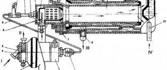
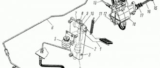
Operating principle of the metering pump When the engine is running, oil is transferred to the metering pump thanks to the NSh oil pump. In the eyes of the housing and rod, spherical hinge bearings 7 are installed, which have channels on the inner ring for lubricating the friction surfaces through a grease nipple in the pin. The cover 11 contains a wiper 13, rod seals 14 and 15 and guide rings 16, which eliminate friction between the rod and the cover.
Description of the installation of the metering unit (GRU) of the MTZ tractor.
Tighten bolt 5. The kit also includes a pumping unit and a distributor.
There are also other malfunctions of the metering pump: When the steering wheel turns, the wheels of the car should, accordingly, turn. Holding filter 13 with your hand, turn out the pressure reducing valve and remove the drain filter. When the oil pressure in the drain hydraulic line drops below 0.08 MPa due to a lack of oil flow due to insufficient oil level in the oil tank, failure of the feed pump or broken hoses, the sensor is activated and the warning lamp for emergency reduction of oil pressure in the control lamp unit lights up. red hydraulic system. If the pump valves become clogged with dirt and other particles, they will not be able to move fluid through the system and regulate pressure. If one of them breaks down, oil is constantly supplied to one of the cylinders, and the steering wheel turns accordingly.
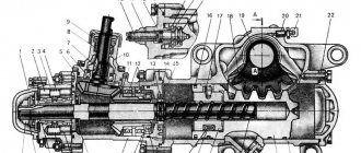
You can buy a ready-made pumping station, but it is better to assemble it yourself - in this case, it will work more efficiently since its elements will be selected in accordance with the tasks that need to be solved when organizing a water supply system. The piston is attached to the rod with a nut 2, which is locked by punching the collar into the grooves of the rod 6. Check the volume of oil and working fluid. This type of dispenser is equipped with a membrane, which acts as a wall through which the working fluid is absorbed and delivered to the required sections during the process of oscillation. How to convert the MTZ gur into a dispenser!
Read more: tractor clutch repair
Devices with a closed center (LS line): differences from models with an open center
These non-reactive hydraulic systems were designed to improve overall steering performance. They provide control of the working parts of special equipment from a single supply pump. The LS system controls changes in working fluid flow and pressure, thereby minimizing energy losses. Such models are usually manufactured in combination with a flow amplifier and a priority flow regulator. The priority valve separates and regulates the flow of working fluid flowing from the feed pump to the steering and brake circuits.
How to properly install the MTZ 82 pump
Installing a metering pump on MTZ 80 and MTZ 82 involves a partial replacement of the power steering system (hydraulic steering) with a HPS (hydraulic steering) mechanism. The MOUNTAIN kit includes:
- special hydraulic cylinder bracket;
- reinforced steering rod;
- two levers;
- hydraulic cylinders for the front axle with a set of pins;
- dosing pump;
- high pressure channels;
- special adapter for the pump.
If necessary, a differential lock valve for the HPS mechanism is also purchased. It is used to replace the lock that is used on the power steering. Such a crane allows you to block the gearbox on unstable sections of the road, which increases the maneuverability of the equipment.
Dual-circuit devices
Provide work in emergency situations. When the feed pump is activated, the metering pump transfers the working fluid to the hydraulic cylinder from two feedback hydraulic motors. If there is no pressure in the feed pump, one hydraulic motor is switched off. This design device is in demand for models whose working volume exceeds 250 cm3. Models: Sauer Danfoss (Denmark), Rexroth Bosh Group (Germany), Eaton (USA), Lifam (Serbia), “First Five-Year Plan” (Yugoslavia).
Hydraulic steering wheels of modern design are increasingly used in special equipment. When choosing this mechanism with a differential device, take into account the required amount of fluid flow and the number of steering revolutions required to turn the wheels from one extreme position to the other extreme.
Types of motor mechanisms and control devices
The pump stroke can be achieved in various ways.
Spring return
This type of motor mechanism has an eccentric cam (item 1) (not physically connected to the plunger), with a spring load on the plunger (item 2).
At full stroke, the piston rod is in constant contact with the cam. By turning the adjusting knob, the length of the plunger is reduced, and the working volume is proportionally reduced with each stroke, which leads to a decrease in pump performance.
To set the required stroke length, a mechanical stopper is installed to prevent the plunger from returning completely; the plunger essentially stops moving until it is struck by the cam on the next revolution.
All our M series pumps are equipped with this type of motor mechanism.
Mechanical return mechanism
This type of mechanism involves connecting a plunger to the connecting rod head (item 3), the cam (item 1) rotates inside the block (item 2), which ensures the pump piston stroke.
Changing/adjusting the stroke length is carried out similarly to the type of mechanism described above. The “E” series pumps are equipped with this type of motor mechanism.
Precision metering pump
One of the main characteristics of a metering pump is that it is easy to fine-tune the required pump capacity.
The flow power is proportional to the displaced volume and, therefore, to the stroke length and speed of the pump.
Below are definitions of some terms related to pump accuracy:
Performance reduction rate (or range) is the design capacity divided by the minimum capacity that can be achieved while maintaining a specified flow repeatability, static accuracy and linearity. The usual ratio is 10:1. Linearity is the maximum deviation from an ideal straight line that can be drawn through test values showing volume changes at a specified performance value. This deviation is expressed as a percentage of the calculated pump performance. The typical value is ±1%. Static accuracy is the change in flow expressed as a percentage of the design capacity under fixed system conditions. The typical value is ±1%. Flow repeatability, expressed as a percentage of design capacity, reflects the ability of a pump to reproduce a specified volume of flow under specified conditions and when the performance value changes and return to the reference test value. The typical value is ±1%.
It must be remembered that to achieve this accuracy, the pump must operate under constant conditions of suction, supply pressure, fluid concentration-temperature-viscosity, and drive speed.
Automatic adjustment
Flow volumes can be changed automatically by process control signals to maintain setpoints or changing process conditions.
This adjustment is achieved through devices such as:
- Pneumatic positioning devices (control signal 3-15 psi)
- Electric servo (control signal 4-20 mA)
- Speed variator
- DC motor current
Why adjust dispenser performance?
In practice, maximum performance is not always necessary. Solenoid pumps are most often used for dosing concentrated chemicals , and in this case it is important not to upset the proportion.
If, when disinfecting drinking water, you exceed the dose of sodium hypochlorite by just a few milliliters, poison will flow from the taps. Therefore, the main goal of regulating the performance of solenoid dispensers is to calibrate the device so that it injects a specific volume of substance with minimal error. For different industries, the magnitude of this error may be different, so there are different models of pumps, each of which will help solve a particular problem.