As you know, the result of engine operation is the creation of torque on the crankshaft, after which the torque is transmitted through the gearbox to the drive wheels. Also, various schemes and solutions can be used in the design of the transmission itself (mono-wheel drive, all-wheel drive, transfer case, etc.).
If we talk about special equipment, you can also quite often hear about an element that is known as PTO (power take-off). In this article we will look at what a power take-off is, as well as why a PTO is needed in various vehicles.
Types of power take-offs
The additional power take-off box serves to transfer energy to equipment installed on the vehicle. Depending on the type of driven mechanisms and the requirements for the device, the characteristics of the KDOM may differ:
- by the number of steps that determine the step between operating modes;
- the possibility of providing the reverse required for the mechanism, for example, the pump requires rotation only in one direction, and the power take-off of a truck crane must be capable of operating in both directions;
- the value of gear ratios that provide a change in angular velocity and transmitted torque;
- the number of shafts structurally included in the PTO;
- the location of the components included in the power take-off device;
- a control signal, which can be purely mechanical, made using a lever, or issued by the car’s on-board computer.
According to the installation location, there are PTOs that are mounted:
- on the side of the gearbox;
- from the end of the gearbox;
- in the gearshift device housing;
- in conjunction with the distribution.
Appearance of the PTO
The method of lubrication of the power take-off gears depends on the method of its installation and the presence of its own oil container. Typically, oil from the crankcase of the main unit is used. When the mechanism is located at the top, a pump is used to supply lubricant to the PTO.
Design
A high-pressure pump consists of a cylinder and a piston, which are a plunger pair. There are 4 such pairs in total, and the unit itself has a V-shape. The design of the device also includes:
- the main body, which contains the pistons and cylinders;
- cam shaft located at the bottom of the housing;
- pistons that transmit torque to the pairs.
As the piston moves, the necessary pressure is created in the cylinder, due to which fuel is transferred to the engine system. The synchronization of the device with the power unit is ensured by spring pushers. The design of the plunger pair, in turn, contains several inlet and outlet valves, as well as special grooves that are responsible for removing excess fuel, restoring the required fluid level in the device. The direction of flow is organized by valve mechanisms, the closing and opening of which occurs automatically.
Reversible box
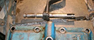
The PTO shown in the figure below is designed for installation in the side of the gearbox housing. The useful power is taken from the intermediate shaft of the gearbox. The gears are in continuous mesh.
Reversible box
The control lever has 3 fixed positions for selecting the operating mode of the power take-off. In the right position, direct transmission is carried out. In this case, the carriage with a gear wheel is constantly in engagement with the intermediate shaft of the gearbox. When moved to the extreme left position, reverse is activated. To ensure reverse motion, the gear wheel is connected to a gear installed inside the PTO gearbox. When moving to the middle position, the driven shaft stops rotating and the additional power take-off box goes into the off position.
Possible breakdowns
The PTO installed on the MTZ-82 tractor may not work correctly for the following reasons:
The MTZ-80 tractor definitely needs to be repaired; the troubleshooting diagram looks like this:
align the holes of the shift roller and the rear axle. This can be done using the control lever. When the holes match, the installation bolt is screwed into them; the locknut of the adjusting bolt is loosened, which, in turn, is screwed into the lever of the switching roller until it stops; the locking bolt is screwed into the glass. Then the adjustment bolt is carefully removed; thus, the glass with springs is removed entirely. It is then disassembled and worn or damaged parts are replaced.
Principle of operation
The pump is designed to provide the necessary pressure, due to which the fuel can move into the cylinder and enter the engine. The principle of operation of the fuel injection pump is that the device performs the following actions:
- First, the fuel passes from the tank to the coarse filter, from where, through a low-pressure fuel pump, it enters the next filter, designed for fine cleaning of the liquid.
- After passing through the filters, the liquid enters the main pump.
- Torque is transmitted from the engine crankshaft, which drives the pushers and the injection pump design.
- The pump organizes the transfer of fuel to the engine, which ensures comfortable operation of the vehicle.
The principle of operation seems to be simple. However, this is not quite true. Any pump in a KAMAZ is a complex mechanism, the operation of which determines the performance of the power unit. Therefore, such devices are made durable and able to withstand high pressures.
Power take-off without gearbox
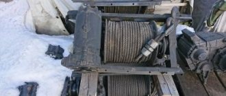
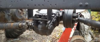
The main difference between gearless PTOs is their simplicity of design and single gear ratio. The image below shows the Ural power take-off, designed to drive a winch. It is mounted to the end of the transfer case, allowing it to receive torque from the input shaft through a movable coupling. Power take-off occurs from the input shaft.
PTO without gearbox
The mechanism is controlled using a special fork. The power take-off is activated by blocking the transfer case input shaft and PTO using a carriage. The lever has two fixed positions. The left one corresponds to power transmission, and the right one corresponds to the off state. The PTO does not provide reverse. To engage the reverse direction, you need to select reverse gear using the gearbox selector.
The parts are lubricated by a plunger pump. This allows the attachment to be used on a stationary vehicle. The pump is located in a special boss of the PTO cover. It also helps lubricate the transfer case.
Application
Power take-off box for Kamaz cars.
It is the main working body for activating various attachments, including the following types:
- Waterer
- Rotary rake
- Active trailers.
- Mounted mowers
- Mechanisms mounted in trailers.
- Planetary mixers.
- Several dozen more types of tractor attachments.
To work with attachments, the PTO rotation speed is standardized. Standard values: 540 rpm, 1000 rpm. A number of tractors are equipped with the ability to switch between these two values. Operating an attachment with an inappropriate PTO rotation speed (540 instead of 1000 or 1000 instead of 540) may result in either insufficient performance of the attachment or damage to it.
When working with attachments, there are two main types of loads.
- The PTO drives the mechanical components of the attachment: either directly or through transmission devices (gearboxes, cardans, V-belt drives, etc.). This type is the most common. In this case, the PTO is under full load
- The PTO drives the hydraulic system of the attachment. This type of PTO operation is applicable only for a small number of devices, usually of low power, equipped with their own hydraulic system (for example, wood splitters driven by a tractor PTO). In this case, the PTO rotates only the hydraulic pump.
PLATFORM LIFTING MECHANISM
Technical description
The lifting mechanism (Fig. 240) is hydraulic and consists of a power take-off box, an oil pump, a hydraulic cylinder, a control valve, a platform lift limiting valve, electro-pneumatic valves, an oil tank with a filter and a system of pneumatic and hydraulic lines. In addition to the specified standardized components, the platform lifting mechanism of the KamAZ-55102 dump truck has a locking device designed to connect the hydraulic system of the tractor with the hydraulic system of the trailer, and a distributor that serves to distribute the oil flow either to the hydraulic cylinder of the tractor or to the hydraulic cylinder of the trailer. The distributor is attached to the control valve.
Schematic diagram of the platform lifting mechanism: a—dump truck KamAZ-5511: 1, 4, 19—electro-pneumatic valves; 2—control valve; 3, 17, 20—pneumatic chambers; 5—24 V current source; 6—fuse; 7—power take-off switch; 8—switch for raising and lowering the platform (1—lowering; 11—raising); 9—indicator lamp for turning on the power take-off; 10—hydraulic cylinder; 11—limit valve; 12—filter safety valve; 13—filter; 14—oil tank; 15—pump; 16—power take-off; 18—hydraulic system safety valve; b— KamAZ-55102 road trains: 1—hydraulic cylinder of the trailer; 2—hydraulic cylinder of the tractor; 3—limit valve; 4— filter safety valve; 5—filter; 6—hydraulic system safety valve; 7—oil tank; 8—pump; 9—power take-off; 10, 12, 14 and 16—pneumatic chambers; 11, 17, 18, 19—electro-pneumatic valves; 13—control valve; 15—distribution edge; 20— switch for the platform lifting mechanism (I—lowering; II—raising); 21—control lamp; 22— hydraulic system distributor switch for tractor or trailer; 23—indicator lamp for turning on the power take-off; 24—power take-off switch; 25—fuse; 26—24 V current source; 27—locking device
Below is the technical specification of the platform lifting mechanism:
| Automobile | KamAZ-5511 | KamAZ-55102 |
| Lifting mechanism control | electro-pneumatic, remote, from the driver's cabin, two switches mounted on the instrument panel | |
| Power take-off | from the gearbox via the power take-off | |
| Transmitted power (average), l. With. | 12 | 10 |
| Efficiency | 0,7 | 0,7 |
| Maximum working pressure, kgf/cm 2 | 140 | 140 |
| Working stroke time (raising a loaded platform) at an engine crankshaft speed of 2300 rpm, s, no more | 19 | 18 |
| Idling time (lowering empty platform), s, no more | 18 | 16 |
| Fuel consumption per 100 operating cycles, l | 5,5 | 5,5 |
| Power take-off ratio | 0,59 | 0,59 |
| Total gear ratio from the engine crankshaft to the driven shaft of the hydraulic pump | 1,26 | 1,26 |
| Recommended engine speed, rpm | 2200—2500 | |
| Number of stages (retractable hydraulic cylinder units) | 3 | 5 |
| Diameter of retractable links, mm | ||
| first | 95 | 142 |
| second | 75 | 117 |
| third | 56 | 95 |
| fourth | — | 75 |
| fifth | — | 56 |
| Working stroke of retractable links, mm | ||
| first | 1100 | 362 |
| second | 1140 | 354 |
| third | 1160 | 190 |
| fourth | — | 354 |
| fifth | — | 349 |
| general | 3400 | 1773 |
| Maximum force when extending links, kgf | ||
| first | 9900 | 26300 |
| second | 6200 | 15000 |
| third | 3450 | 9900 |
| fourth | — | 6200 |
| fifth | — | 3450 |
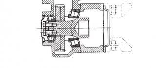
Power take-off (Fig. 241)—with an oil pump, attached to the gearbox housing on the right side. Between the flanges of the power take-off housing and the gearbox, sealing gaskets are installed, with the help of which the mesh of the gears is adjusted at the factory. Therefore, if it is necessary to replace the gaskets, their overall thickness must be maintained.
The drive gear 7 of the power take-off is fixed at one end of the drive gear axis, the other end of which enters the cavity of the diaphragm chamber and is connected to the diaphragm 3. The cavity of the diaphragm chamber is closed by a cover 1 with a threaded hole for air supply. The diaphragm is held by spring 4 in its uppermost position. The axis of the drive gear is kept from rotating by a set screw 5, the end of which fits into the groove of the axis. When air enters the chamber cavity, the axis with the drive gear moves above the diaphragm. The drive gear has two ring gears, one of which is permanently connected to the intermediate gear of the power take-off, and the other engages with a gear half-coupling 9, which transmits rotation through the prism 10 and clutch 11 to the drive shaft of the pump 13. When air is released from the working cavity of the diaphragm chamber the spring disengages the drive gear from the gear half-coupling, while the connection with the intermediate gear is not interrupted.
The power take-off can only be turned on when the air pressure in the vehicle's pneumatic system is at least 5 kgf/cm 2 and when the clutch is disengaged.
Since January 1984, a modernized power take-off (PTO) of increased reliability has been introduced on KamAZ-5511 and -55102 dump trucks.
Power take-off: a—before improvement: 1—cover; 2—washer; 3—diaphragm; 4—spring; 5—set screw; 6, 8, 17—bearings; 7—drive gear; 9— gear half-coupling; 10—prism; 11—coupling; 12—gasket; 13— pump; 14, 15, 16—circlips; 18—idler gear; 19—bolt; 20, 21—o-rings; b—after improvement; 1—cork; 2 and 21—gaskets; 3—idle gear axis; 4 and 16—washers; 5 and 23—bearings; 6—idler gear; 7—thrust ring; 8—lock washer; 9—nut; 10 and 12—rings; 11—compensator; 13—adjustment screw; 14—PTO housing; 15—spring; 17—pneumatic cylinder body; 18—O-ring; 19—piston; 20—pump NSh32-L-2; 22—half coupling; 24— gear
In the crankcase 14 (Fig. 241, a) the driven gear 24 is placed in ball bearings 23. On the axis 3 on ball bearings 5, using a nut 9 and a washer 8 with a bending antenna, the intermediate gear 6 is fixed. The axis is protected from rotation by a set screw 13. During assembly, the screw it is screwed into the crankcase 1 until it stops at the bottom of the groove on axis 3, and then it is unscrewed 1.5 turns and opened. This ensures that the axis can move in the longitudinal direction.
The end of the axle with a piston 19 attached to it with a cuff 18 enters the body of the pneumatic cylinder 17, which is attached to the PTO housing. In the initial position, the axis is held by spring 15. Oil leakage from the PTO cavity into the pneumatic cylinder cavity is prevented by ring 12. To connect to the pump shaft, a half-coupling 22 is used, which is connected through a compensator 11 to the driven gear 24, which compensates for possible distortions of the axis of rotation of the driven gear and the pump shaft when installing the pump on COM.
In the initial position, the intermediate gear is in constant engagement with the gearbox gear. When compressed air is supplied to the pneumatic cylinder body, the intermediate gear moves to the left and its ring gear engages with the driven gear ring. The torque from the driven gear is transmitted to the pump shaft.
It should be noted that when installing a modernized PTO, a left-hand rotation NSh32-2 pump is used, which entails the use of modified high and low pressure pipelines from the pump to the control valve and oil tank. This remark must be taken into account when replacing old PTOs in operating organizations with modernized ones.
Oil pump—gear type, high pressure. The pump flow is 56 l/min at a shaft speed of 1900–2000 rpm.
To ensure normal operation of the pump and increase its service life, it is necessary to carefully filter the oil poured into the tank.
The hydraulic cylinder of the KamAZ-5511 vehicle lifting mechanism is telescopic, plunger, single-acting (Fig. 242). The housing 15 of the hydraulic cylinder contains retractable links 14, the stroke of which is limited when extending by locking rings 13, and when moving downwards by locking rings 18. The direction of the retractable links is ensured by guide half rings 17 and bushings 9, which are held by locking rings 7. To increase the performance of the hydraulic cylinder, the outer surfaces of the retractable The links are knurled, chrome plated and polished. The retractable links are sealed with rubber cuffs 11, located between spacers 12 and protective rings 10. The cavity of the hydraulic cylinder is protected from dust and dirt from the outside by cleaners 8. A bottom 5 is inserted into the body of the hydraulic cylinder from below, the shoulder of which is connected to the shoulder of the body by half rings 20. The half rings are connected by a clamp 19, fastened with a bolt 3, locked with a washer with bent antennae. The hydraulic cylinder has ball heads 6, the spherical part of the ball head is fixed in the hydraulic cylinder support 22, forming a movable connection. Ceramic-metal liners ensure the operation of this connection without lubrication.
A pipe 16 with a threaded end is welded to the body of the hydraulic cylinder, to which a high-pressure hose is attached.
Hydraulic cylinder: 1—hydraulic cylinder support; 2—liner; 3—nut; 4— ball head; 5—lock washer; 6 and 10—thrust rings; 7—wiper clips; 8—cleaners; 9—washers; 11—protective rings; 12—cuffs; 13—spacers; 14—plungers; 15 and 19—split rings; 16—hydraulic cylinder body; 17—pipe; 18—half rings; 20— half ring of the clip; 21—clamp; 22—bottom of the hydraulic cylinder; 23—bolt
The control valve (Fig. 243) is used to control the flow of working fluid in the hydraulic system of the tipping mechanism. Seats 4, 17 of valves 18, 5 are pressed into body 1 of the control valve and nuts 16, 10 are screwed in, serving as guides for pushers 15, 7. A special connection of valves with dovetail pushers prevents the valves from jamming in the seats if the axes of the pushers and seats do not coincide . Pushers with attached valves at one end and the other ends, on which diaphragms 13 and 6 are attached, enter the cavities of pneumatic chambers closed by covers 14, 8. Spring 12 of pusher 15 holds valve 18 in the open position, and spring 9 presses valve 5 to the seat. The pushers are sealed with rubber rings 11, and the pusher 7, in addition, has a drainage hole B.
In the neutral position, oil from the pump through the pipeline through the opening of fitting 19 enters the control edge and, passing through the open valve 18, goes to drain through fitting 21.
When air is supplied to the cavity of the pneumatic chamber above the diaphragm 13, valve 18 closes. At the same time, air is supplied to the cavity of the pneumatic chamber under the diaphragm 6 and valve 5 opens. Oil passes through valve 5 and fitting 2 into the cavity of the hydraulic cylinder. When air is released from the cavities of the pneumatic chambers, valve 5 closes and valve 18 opens. Since valve 5 is closed, the hydraulic cylinder line is blocked and the platform is held in a raised position, and the oil, when the pump is running, goes from it to drain through valve 18 of the control valve.
If air enters only into the cavity of the pneumatic chamber under the diaphragm 6, valve 5 opens and oil from the cavity of the hydraulic cylinder goes through this valve and valves 18 to drain. A safety valve 20 is screwed into the control valve body, which, when screwed in with collar B, cuts into the body of the control valve body and disconnects the pressure and drain lines. In case of overload, the pressure in the system increases and the safety valve is activated, releasing oil into the oil tank.
The platform will stop lifting until the overload is removed. The response pressure of the safety valve is strictly adjusted at the factory, and changing it during operation is prohibited.
Control valve: 1—control housing; 2, 19, 21—fittings; 3—sealing rings for fixed joints; 4, 17—valve seats; 5, 18—valves; 6, 13—diaphragm; 7, 15—pushers; 8, 14—pneumatic chamber covers; 9, 12—springs; 10, 16—guide nuts; 11—sealing rings for movable joints; 20—safety valve; B—drainage hole; B—shoulder
The platform lift limitation valve (Fig. 244) is fixed to the bracket of the first cross member of the subframe. A bushing 1 with an o-ring 5 is screwed into the housing 6. A rod 4 with an adjusting bolt 2 at one end passes into the hole of the bushing, the other end of which faces the valve 8. The adjusting bolt ends with a spherical head and is locked with a lock nut 3. In the closed position, the valve is pressed against the body spring force 7.
When you press the spherical head of the adjusting bolt, the rod moves and opens the valve, while the pressure and drain lines communicate.
Platform lift limitation valve: 1—bushing; 2—adjusting bolt; 3—lock nut; 4—rod; 5—o-ring; 6— body; 7—spring; 8—valve
The electro-pneumatic valve (Fig. 245) consists of housing 3, housing cover 1, electromagnet 4, rod 5, springs 6, valves 8. Air from the cylinder is supplied to terminal I into the cavity in the valve cover. When the electromagnet is turned on, the rod, extending, presses the upper valve 8 to the housing seat. In this case, the lower valve 8 moves away from the seat and air from the cavity in the valve cover through the valve in the body and terminal III flows to the pneumatic actuating chambers installed on the power take-off box or control valve. When the electromagnet is turned off, the lower valve is pressed with the help of a spring to the housing seat, and the upper valve moves away from the seat. The air from the pneumatic chamber escapes into the atmosphere through outlet II.
Electro-pneumatic valve: 1—cover; 2—fitting; 3—body; 4—electromagnet; 5—rod; 6—spring; 7, 9—gaskets; 8—valve
The oil tank is stamped from two halves. At the top of the tank there is a filler neck and a filter mounting flange, at the bottom there is an oil drain hole, closed with a threaded plug, and a suction pipe. A filter mesh is installed in the filler neck. The neck is closed with a threaded cap with a hole connecting the tank cavity to the atmosphere, and an oil level indicator with lower and upper marks. The oil level in the tank should be within these marks. The level is measured with the platform lowered. To prevent dust and dirt from entering through the hole in the filler cap, a hair pack is provided. The oil tank filter is attached to the flange on the drain line.
Oil tank filter (Fig. 246). From the drain line, oil flows through pipe 4 into the cavity of filter housing 2 and through filter elements 3, filter pipe 1 goes into the tank. If the filter elements are excessively clogged, the pressure in the drain line increases, as a result of which ball valve 5 opens and the oil is drained into the tank, bypassing the filter element.
Oil tank filter
The hydraulic cylinder of the KamAZ-55102 dump truck (Fig. 247), in contrast to the hydraulic cylinder of the KamAZ-551 I dump truck, has five retractable links. It is attached to the subframe by pin 1, which has a threaded hole for connecting a high-pressure hose. A bottom 20 with a hole for a plug 21 to drain the sludge is screwed onto the hydraulic cylinder body from below. Ball head 6 is attached to the hydraulic cylinder plunger using a locking ring 10.
Hydraulic cylinder for lifting the platform of a KamAZ-55102 dump truck: 1—axle; 2—spacer; 3—protective ring; 4—mud lifter; 5—hydraulic cylinder support; 6— ball head; 7—insert; 8—liner; 9— locking screw; 10—ring for fastening the ball head; 11—retaining ring of the guide sleeve; 12—guide bushing, 13—cuff; 14—upper retaining ring; 15—hydraulic cylinder body; 16—retractable link; 17—O-ring; 18—guide half-ring; 19—bottom retaining ring; 20—bottom of the hydraulic cylinder; 21—drain plug
A distributor is attached to the control valve (Fig. 248), which serves to distribute the oil flow either to the hydraulic cylinder of the tractor or to the hydraulic cylinder of the trailer. In body 1, with the help of retaining rings 5, seats 6 are installed, through which valves 7 and 8 pass. The threaded end of valve 8 with diaphragm 12 enters the cavity of the pneumatic chamber, closed by lid 13. Spring 11 holds the valve in the extreme left position. The seats of the bushings and valve are sealed with rings 9 and 10, respectively. Possible leaks through the valve seals are removed on the one hand through the drain hole of the plug 4, on the other through the hole in the pneumatic chamber under the diaphragm.
The oil passes through the hole in the distributor body under valve 7 through the seat, fitting and enters the hydraulic cylinder line of the dump truck. When compressed air is supplied to the cavity of the pneumatic chamber above the diaphragm, valve 8 moves to the right, the hydraulic cylinder line of the dump truck is closed and oil begins to flow through fitting 2 into the trailer hydraulic cylinder line.
Distribution valve: 1—body; 2—fitting; 3, 5—retaining rings; 4—plug; 6—saddle; 7, 8—valves; 9, 10—sealing rings; 11—spring; 12—diaphragm; 13—cover
The locking device (Fig. 249), designed to connect the hydraulic system of the KamAZ-55102 dump truck-tractor with the hydraulic system of the trailer, consists of two buildings 1 and 7, one of which is connected to the pressure line of the dump truck-tractor, the other - to the trailer. In the case of a dump truck operating with a trailer, both parts are connected to each other by a nut 5. In this case, the balls 3 and 4 of the shut-off valves are pressed by each other from the support belts. When working without a trailer, it is necessary to disconnect its line; to do this, simply unscrew the nut.
Then the balls, under the influence of springs, will block the holes in the housings and thereby prevent oil from leaking out of the hydraulic systems.
Locking device: 1—trailer locking device body; 2, 6—springs; 3, 4—balls; 5—nut; 7—trailer locking device housing; 8—trailer plug; 9—tractor plug
Maintenance
For TO-1, perform the following operations:
— check the tightness and condition of pipelines and components of the platform lifting mechanism, eliminate malfunctions;
— bring the oil level in the tank to normal (on the oil level indicator with the platform lowered);
— wash the oil filter and filter elements of the oil tank.
At TO-2:
— check the condition and operation of the control crane and the platform lift limitation valve, the safety cable deflection arm;
— secure the front subframe brackets and subframe coupling bolts, catcher-shock absorber, platform shock absorbers, power take-off and oil pump; drain the sediment from the hydraulic cylinder.
To drain sludge from the hydraulic cylinder of a KamAZ-5511 dump truck, disconnect the high-pressure hose, release the bottom ball head by lifting the body to its highest position, remove the ball head from the support on the subframe. Then, holding the hydraulic cylinder in the uppermost position, release the half-rings of the hydraulic cylinder from the clamp, remove the half-rings and the bottom. After draining the sludge, install the hydraulic cylinder into the support in the reverse order. When removing and installing the bottom, make sure that the rubber ring installed in the groove of the bottom is intact.
To adjust the lifting angle of the KamAZ-5511 dump truck platform (if the locking pins 3 (see Fig. 189) do not fit into the holes in the subframe brackets when the platform is fully raised), do the following:
- Unscrew locknut 3 of adjusting bolt 2 (Fig. 250);
— screw the adjusting bolt into the rod until it stops;
— lift the platform to a position where the platform locking pins fit freely into the holes in the subframe brackets, and lock the platform in this position with the locking pins;
— unscrew the adjusting bolt 2 from the valve rod until it stops in the hydraulic cylinder body 1 and lock it with lock nut 3.
Adjusting the lifting angle of the KamAZ-5511 vehicle platform: 1—hydraulic cylinder; 2—adjusting bolt; 3— lock nut; 4—platform lift limitation valve
Unlock the platform, lower it and raise it again. make sure that the lifting stops when the axis of the locking pins coincides with the axes of the holes in the subframe brackets.
To adjust the lifting angle of the KamAZ-55102 dump truck platform (Fig. 251):
— lift the platform to one side at an angle of 50° and place a stop under it;
— unscrew the locknut 5 of the adjusting bolt 4 and unscrew (or screw in) the bolt so that the specified platform lift angle is ensured, then tighten the locknut;
— in the same way, adjust the amount of tilting of the platform in the other direction using adjusting bolt 3;
- Raise the platform again and make sure that its lifting is limited to angles of 48-52°.
Mechanisms for limiting the lifting of the KamAZ-55102 vehicle platform: 1, 4—adjusting bolts; 2. 5—lock nuts; 3—lever; 6—spring; 7—lever axis; 8—platform lift limitation valve; 9—hydraulic cylinder
During seasonal maintenance, change the oil in the hydraulic system of the platform lifting mechanism.
When changing the oil for the first time, remove and wash the bottom of the hydraulic cylinder, as well as the oil tank filter with a set of filter elements. To drain oil from the hydraulic system, unscrew the drain plug from the oil tank, and to completely empty the system, disconnect the hose from the suction pipe of the pump.
You can only work with the platform completely lowered!
The procedure for refueling the hydraulic system is as follows:
— unscrew the oil tank filler cap, remove, wash and reinstall the strainer;
— fill in oil to about on the oil level indicator;
- Raise and lower the platform 3-4 times at an average engine speed (1100-1300 rpm) to pump the system and remove air from it;
— check the oil level, if necessary, add to about.
Rear PTO MTZ functions and device
Belarusian tractors MTZ-80, MTZ-82, MTZ-82.1, MTZ-1221, 1523, MTZ-892, YuMZ, T-40. Agricultural machinery plows, cultivators, walk-behind tractors, mowers, seeders
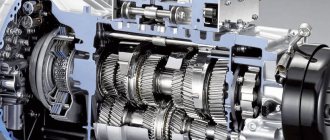
In this article we will look at the design features of the MTZ rear power take-off shaft. So, the MTZ rear PTO includes a gearbox, a friction multi-disc clutch for disengaging and engaging, as well as a friction-type shank stopping brake with a single disc.
Let's look at the unit's design in more detail below.
Design and operating features of the MTZ power take-off shaft
A two-speed MTZ PTO gearbox is installed in the rear axle housing, consisting of:
- Spur-toothed coaxial gears, one of which is driving, the other is driven;
- The gears are constantly meshed with double-rimmed intermediate gears located symmetrically;
- Axles pressed into the gearbox housing.
The drive and driven gears have holes that are designed to connect to the splines of the shanks and are mounted taking into account the operating mode. The rotation of the shanks occurs in ball bearings, they are fixed with a retaining ring to prevent axial movement.
The PTO or power take-off shaft of the MTZ 80 is turned on and off by a clutch, and the shank is stopped by a brake with one disc. Metal-ceramic discs are mounted on the splines of the coupling related to the drive shaft. There are steel discs in the slots of the drum attached to the drive gear. When the PTO engages, the oil acts on the piston, causing it to compress the disc pack and connect the drive shaft to the gearbox gears. This is how power is transferred from the shaft to the shank.
Switching off the PTO causes a drop in pressure. In this case, the piston returns to its original position under the action of springs. The drive shaft is disconnected from the gearbox and shank.
Switching modes of the MTZ 82 power take-off shaft
To stop the shank, a hydraulically controlled single-disc brake is used. It is installed in the gearbox housing and includes:
- Piston;
- Friction type disc;
- Connecting splines;
- MTZ drum;
- Tractor support disk.
Turning on the piston causes the discs to compress under oil pressure. The drum and shank are braked. A speed of 540 rpm and 3.3 rpm can be achieved by removing the retaining ring and the shank marked “1000”.
Instead, a part marked “540” is installed, which fits with splines into the hole on the driven gear and stops the shank with a ring. To return to the previous mode, it is necessary to change the shank to the unit with the o.
The MTZ rear PTO drive is switched between independent and synchronous, and is also turned on with a handle located on the left side of the driver’s seat. Its middle position corresponds to the neutral position. Moving the handle up turns on the independent drive, downwards turns on the synchronous drive.
The independent PTO drive is activated when the engine is not running or at minimum crankshaft speed. The synchronous drive is turned on by disengaging the clutch. When the rear PTO is not operating, the handle should be in the neutral position.
After switching on the synchronous drive, the tractor is prohibited from moving at a speed of more than 8 km/h. Adjusting the MTZ power take-off shaft is easy to do yourself. However, read about the features of repairing the MTZ rear PTO in the following articles of our blog.
We remind you that if you want to buy spare parts for the MTZ tractor, pay attention to our catalog. The range of original parts includes components for agricultural machinery, as well as for MAZ trucks
Dependent type PTO
Clutch-dependent gearboxes are installed on vehicles with manual transmission. This mechanism is installed if there is no need to turn on attachments on the go. For example, the power take-off box of a dump truck is often made in a dependent design.
The main advantages that KZOM has:
- light weight;
- ease of repair of power take-offs;
- no load on the engine when the PTO is off;
- simplicity and reliability of the design, allowing you to confidently operate both new and repaired boxes, which is confirmed by an extensive sample;
- low maintenance requirements;
- increased safety, since the drive cannot be activated while moving, which is especially important for a dump truck PTO.
Installation of the dependent type of boxes is quite simple. Installation is carried out in a specially designated place, after removing the special hatch. When positioned at the top, a pump is used. If necessary, dismantling the KZOM does not cause difficulties and does not affect the performance of the main power transmission.
Video 505 vm.-77 MTZ-50 MTZ-50 year of manufacture 1977 major overhaul
coupling
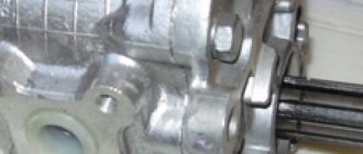
Upon visual inspection, oil smudges are visible on the shaft cover.
This indicates wear of the cuff or gasket. In this case, the shaft is dismantled and the gasket between the PTO cover and the rear axle is replaced. If the leak comes from the shank side, the stopper ring is removed, the shaft is pressed out and the cuffs are replaced.
The MTZ-80 tractor does not produce maximum power when working with attachments
The probable cause is the band brakes. They need adjustment or complete replacement. If the adjustment does not help solve the problem, it is necessary to remove the PTO from the tractor and measure the thickness of the brake bands. If the thickness is less than 2.5 millimeters, the tapes are replaced.
At maximum load on the tractor, extraneous noise is heard
This indicates wear of the satellite axles, support bearings or splined joints. The technical condition of these components can be assessed only after the PTO is removed from the tractor. After this, the teeth are inspected and the gaps are checked. If repair is possible, the parts are restored; if not, they are replaced.
If the speed reducer gearbox has been dismantled or disassembled, the PTO will need to be checked or adjusted. To do this, place the tractor on a jack (under the drive wheels) and turn the take-off shaft, alternating the gears.
When performing this operation, the tractor PTO must be switched to synchronous mode. When scrolling, the gear wheels should rotate freely.
Attention, TODAY only!
Similar
Principle of operation
The pump is designed to provide the necessary pressure, due to which the fuel can move into the cylinder and enter the engine. The principle of operation of the fuel injection pump is that the device performs the following actions:
- First, the fuel passes from the tank to the coarse filter, from where, through a low-pressure fuel pump, it enters the next filter, designed for fine cleaning of the liquid.
- After passing through the filters, the liquid enters the main pump.
- Torque is transmitted from the engine crankshaft, which drives the pushers and the injection pump design.
- The pump organizes the transfer of fuel to the engine, which ensures comfortable operation of the vehicle.
The principle of operation seems to be simple. However, this is not quite true. Any pump in a KAMAZ is a complex mechanism, the operation of which determines the performance of the power unit. Therefore, such devices are made durable and able to withstand high pressures.
Diagrams of power take-offs of various cars
Rice. Diagram of the MAZ 5334 AC-8 power take-off: 1 - rubber diaphragm; 2 - spring; 3 - rod; 4 — body; 5 — shift fork; 6 - cuff; 7 - splined shaft; 8 - flange; 9 — pin; 10 - gear; 11 - idler gear; 12 — tachometer primary converter; a - camera
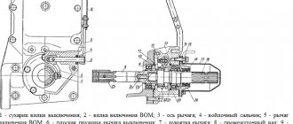
Rice. Diagram of the KSM-68B power take-off: 1 - gear shift rod; 2 - body; 3 — gear shift lever; 4 — PTO power fork; 5 — gear (Z = 17); 6, 7, 10, 20 — bearing; 8 - coupling; 9 — secondary shaft; 11 - cover; 12 — oil seal; 13 - flange coupling; 14 — handle; 15 — gear shift fork; 16 — gear (Z = 41); 17 — roller bearing; 18 — PTO switch rod; 19 — gear axis; 21 — primary shaft; 22 — gearbox input shaft gear; I - lateral clearance in engagement
Rice. Power take-off box of the CMK-10 crane (a) and its kinematic diagram (b): 1, 5 - flanges, 2 - bearing; 3, 4 - input and output shafts; 6 — body; 7 - crown; 8 — shift clutch; 9 — ring gear; 10 - hub; 11 - pulley; 12 - fingers
Rice. Power take-off RK-5: 1 — gear block PK-5-11A; 2 - axis RK-5-13; 3 — box body PK-5-01; 4 — pump NSh10; 5 — pump shaft RK-5-16B; 6 — plug RK-5-26A; 7 — switching roller RK-5-21; 8 — shift roller RK-5-26; 9 — plug RK-5-27A; 10 — gear RK-5-14A; 11 — selection shaft RK-5-31A; 12 — gear RK-5-15A
Rice. Power take-off ZIL-131: 1 — gear fork rod; 2 and 23 - cuffs: 3 - o-ring; 4 — power plug; 5 — ball retainer; 6 — rod plug; 7 — rear bearing cover; 8 — ball bearing; 9 — gear wheel; 10 - main shaft; 11 — axis of the constant-mesh gear; 12 — support washer; 13 — intermediate gear wheel of constant mesh; 14 — axis of the gear block; 15 — gearbox housing; 16 — gear block; 17 — roller bearing; 18 — support washer; 19 — spacer ring; 20 — bearing cover gasket; 21 — front bearing cover; 22 - flange; 24 — flange support washer; 25 - filler plug; 26 — power take-off lever; 27 — drain plug; 28 - nut; 29 — lock nut; 30 — lever bracket; 31 - gasket
Rice. MAZ power take-off: 1 — intermediate gear; 2 - body; 3 — driven gear; 4 - fork; 5 — locking bolt; 6 — lock washer; 7 - axis; 8 — ball bearing; 9 — roller bearing; 10, 14 — covers; 11 - glass; 12 - spring; 15 - nut; 15 — pneumatic chamber; 16 - diaphragm; 17 — washer; 18 — thrust washer; 19, 23, 25 — gaskets; 20 - screw; 21 — sealing ring; 22 — rod; 24 - shaft
Rice. Power take-off from the transfer case (KOM-1) (for special equipment): 1 - crankcase; 2 - spacer sleeve; 3 and 20 - nuts; 4 and 18 — bearing caps; 5 - shaft; 6 and 23 - ball bearings; 7 — carriage; 8 - plug; 9 — hatch cover; 10 — shield; 11 - switch; 12 — switching chamber; 13 - membrane; 14 - spring; 15 — rod; 16 - gasket; 17 — adjusting washer; 19 - flange; 21 — spring washer; 22 and 28 — support washers; 24 — retaining ring; 25 — toothed ring of constant engagement; 26 - plug; 27 - axis; 29 — roller bearing; 30 - spacer ring; 31 — forks; 32 - protect the valve; 33 — lock bolt; 34 - locking plate
Rice. Electrical diagram of the power take-off: 1 - switch for the power take-off warning lamp; 2 — air valve solenoid; 3 - three-terminal connecting panel; 4 - power take-off relay; 5 — front axle activation relay; 6 - two-socket connector; 7 - switch; 8 — control lamp for turning on the power take-off; 9 - 20 A fuse
Additional clutch control drive
Schematic diagram of an additional mechanical control system for the clutch mechanism on a tanker truck
1 – release bearing; 2 – fork; 3 – pedal; 4 – coupling; 5 – lock nut; 6 – low thrust; 7 – rod; 8 – button; 9, 12, 18 – levers; 10 – latch; 11 – gear sector; 13 – intermediate support; 14 – high thrust; 15 – axis; 16 – intermediate rod; 17 – spring; 19 – roller
An additional clutch mechanism control system is designed to disable (turn on) the fire pump from the chassis engine. The figure shows a schematic diagram of a mechanical additional clutch control system for a fire tanker (used on AC models 63B and 137A of early releases, PM-548 and a number of others).
In the pump compartment of the fire truck there is a clutch lever 9 and a gear sector 11. To disengage the clutch, you must press the button 8 with your finger, which, through the rod 7, will disengage the latch 10 from the gear sector, and move the clutch lever to the “pull” position and fix it in the rearmost position (in the direction of the arrow). In this case, the small rod 6 will move, turning the lever 12 of the intermediate support 13 with the simultaneous movement of the large rod 14, onto which the coupling 4 with a slot is screwed. Next, the clutch acts through the axis 15 of the clutch pedal and the intermediate rod 16 on the lever 18 of the clutch shaft 19. The fork 2 of the roller acts on the release bearing 1, ensuring that the clutch is disengaged. When you press the clutch pedal 3 in the driver's cabin, its lower axis moves freely along the slot of the clutch 4, without affecting the rod system of the additional clutch control system. The return of the clutch pedal to its original position occurs under the action of the return spring 17. The free play of the clutch pedal is adjusted by changing the position of the clutch 4 installed on the intermediate rod. The amount of clutch pedal free play must correspond to the lower limit of the range established by the chassis manufacturer. For example, if on a ZIL-131 car the free play is 35...50 mm, then for a tanker on this chassis the free play should be set to 35-40 mm (no more). With a larger free play, due to inevitable drive play, incomplete disengagement of the clutch will occur.
To adjust the length of the linkages of the clutch control system, it is necessary to place the clutch lever in the pump compartment in the extreme forward fixed position, release the lock nut 5 of the large linkage and by rotating the clutch 4 set the required length of the linkages. When moving the clutch lever to the rearmost position, achieve a position such that when you press the clutch pedal, its free play is within the required value. When moving the clutch lever to the rearmost fixed position, the clutch must be completely disengaged so that when the engine is running and the PTO is engaged, the propeller shaft to the pump does not rotate. After completing the adjustment, tighten the locknuts.
Conclusion on the issue: for the convenience of working on fire trucks, an additional clutch drive is provided.
Independent power take-off design
Installation of an independent type PTO is possible on a vehicle with any type of transmission. The main advantage is the ability to turn on the mechanism both when the vehicle is stationary and on the move. An example of a device is a KAMAZ power take-off. Placement is possible both to the right and left side hatch of the gearbox, as well as from the rear end and depends on the model of the gearbox. A pump is used for lubrication.
The speed of rotation of the gearbox shafts and the transmitted power can be controlled directly using the engine. Switching the PTO on and off is often accomplished using electropneumatics and hydraulics. This type of gearbox is widespread on cars with automatic transmission.
Health
News
- My friend always drinks ginger tea, and in 10 years of our friendship, I have never seen her get the flu or complain about heartburn.
- How to maintain weight for a long time and without restrictions? Changing not your diet, but your lifestyle: 6 rules for healthy weight loss
- What is the best time to drink green tea to get the benefits for the body?
- Unexpected reasons for weight gain: too warm rooms and a few more
- A young mother admitted: she was able to lose weight by learning to cook
- As a child, our parents often scared us that our favorite soda was dangerous to our health. Today these are not just horror stories, but scientifically proven facts.
- The terrible consequences of a prolonged runny nose - sinusitis
- If your nerves are getting worse: foods that will help strengthen the nervous system
- How to make your body lose weight even in your sleep: simple habits that will help you lose weight while you rest
- A dentist friend told me how to get rid of plaque at home using baking soda
- Skin diet: 10 foods that will get rid of pimples on your face
- If you take off your shoes when entering the house because you're worried about bad bacteria causing illness, relax. According to experts, these fears are exaggerated
- What happens to our body when we dive into cool water: 5 unnoticeable but very important changes for the body
- How to choose the most delicious and fresh tropical fruits: learning to choose pineapple, pomegranate and much more
- I always suffered from having trouble falling asleep. Kuma taught the banana method
- I asked the stylist what hairstyles make you look younger. She named 7 haircuts
- The doctor said that certain foods (hot sauces, baked goods, and more) can cause bad dreams.
- OMAD - “once a day” diet, or How to lose excess weight without giving up sweets and fatty foods
- Painting your nails is harmful to your health: study results
- What will happen to the body if you start eating buckwheat porridge three times a week
- Only 1 in 100 people have this feature: preauricular sinuses. What are they and why do we need them?
We wash our hands and eat: simple soap and water disinfects hands better than other means (doctor’s advice)
In fact, to truly remove dirt and harmful germs from your hands, there is no better solution than simple soap and water. The main thing is to use them...
Health
Eating stress food and skipping breakfast: what habits prevent you from losing excess weight
Maintaining a healthy weight is the result of a combination of factors. Of course, this has to do with diet as well as lifestyle. Some items may...
Health
Goodbye fillings! Chinese scientists have developed a gel that restores tooth enamel
Tooth enamel is the strongest tissue in the human body. But unfortunately, strong does not mean durable. Under the influence of sugars, acids, as well as...
Health
Why doesn't the weight come off? 7 breakfast options we are used to that prevent us from losing weight
After a long hungry night, our body begins to crave food. After all, without proper fuel, we have little energy and our mood deteriorates. But sorry...
Health