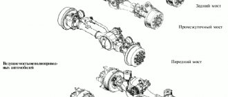
Power steering KamAZ: device, adjustment
KamAZ is perhaps the most common truck in Russia. Back in Soviet times, the trucks of the Kama Automobile Plant established themselves as reliable, unpretentious and quite comfortable vehicles. Most drivers in the USSR considered it a blessing to work at KamAZ. One of the reasons for this was the presence of power steering (power steering) on the truck, which was an unheard of luxury for the domestic automobile industry.
However, this unit, which greatly facilitates the driver’s work, has to be maintained and also repaired. In this article we will talk about how to do it correctly and when.
What kind of power steering are there?
Kinds
- Electric power steering (EPS)
- Electric power steering (EGUR)
- Power steering (power steering)
- Mechanical power steering (conditionally) is a steering mechanism with an increased (compared to conventional) gear ratio.
- Pneumatic power steering (for example on ZiU-5)
Interesting materials:
What happens if a person eats boric acid? What happens if you wear high heels for a long time? What happens if I don’t pick up the parcel from the post office? What happens if you drop iodine on cottage cheese? What happens if swallows fly into the house? What happens if you eat at night? What will happen if all the birds on the planet disappear? What happens if you don’t pick up the goods at the post office? What happens if you apply hydrogen peroxide to your face? What happens if a patent is violated?
Problems solved by KamAZ power steering
Not all passenger cars have power steering. And it’s clear why, cars are quite light and can be driven without power steering. However, try to do this on a heavy KamAZ. On a car that weighs 10 tons without load, it is almost impossible to turn the steering wheel without power steering, unless, of course, you are a weightlifting champion. Therefore, in cases where the amplifier fails, driving the car turns into real torture. And any driver tries to fix it as quickly as possible.
The design of a typical KamAZ power steering
Any power steering consists of the following main components:
- distributor;
- Hydraulic cylinder;
- Working fluid;
- Pump.
Modern power steering systems are also equipped with an electronic control unit.
A special feature of the KamAZ hydraulic booster is that all its actuators are assembled in one housing. The working fluid is fluid for power steering and automatic transmissions of the ATF type.
The operating principle of power steering is as follows. The main thing to always remember is that the amplifier only works when the power unit is running. It is started by a belt coming from the crankshaft, which drives the pump. On KamAZ trucks, pumps can be rotary or axial piston.
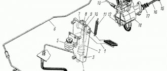
General KamAZ steering device
- steering wheel;
- steering column;
- bracket;
- flange;
- adjusting nut;
- cardan transmission;
- radiator;
- distributor;
- bevel gear;
- steering gear;
- longitudinal steering rod;
- bipod;
- bipod shaft;
- pump;
- tank.
When the engine starts, the pump (14) pumps working fluid from the tank (15). Fluid under high pressure enters a spool-type distributor, which then helps the driver rotate the steering wheel (1).
A special device is used to monitor the force on the steering wheel. On KamAZ, this is a torsion bar, which is located in the section of the steering shafts.
When the car moves in a straight line and there is no force on the steering wheel, then the torsion bar is open and the distributor valves close. In this case, the power steering does not work, and the working fluid is sent back to the reservoir.
When the driver begins to turn, the torsion bar rotates and the spool opens the channels through which the working fluid under pressure is directed to the power steering mechanisms. This makes it easier to rotate the steering wheel.
In cases where the steering wheel is turned all the way, the safety valves open, they relieve fluid pressure and, in essence, turn off the amplifier. This is done in order to avoid damage to the steering mechanism, since the force created by the power steering is quite enough to break it.
GUR KamAZ-5320
KamAZ-5320 can be considered a classic car. This is one of the most common heavy trucks in the vastness of our country. The car was produced back in 1976, and its production was completed at the very beginning of the 21st century.
Power steering KamAZ-5320 can be considered the simplest among the entire family of Kama trucks. It has the following device:
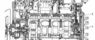
Steering mechanism of the KamAZ-5320 car
1, 14, 22 and 42 – covers; 2 – jet plunger; 3 – control valve body; 4 and 36 – springs; 5 – adjusting shims; 6 and 12 – ball bearings; 7 – drive shaft with gear; 8 – needle bearing; 9 – sealing device; 10 – body; 11 – driven gear; 13, 32 and 44 – retaining rings; 15 – thrust ring; 16 – sealing ring; 17 and 26 – screws; 18 – sector; 19 – bipod shaft; 20 – bypass valve; 21 – cap; 23 – crankcase; 24 – piston-rack; 25 – plug; 27, 30, 39 and 41 – nuts; 28 – gutter; 29 – ball; 31 – lock washer; 33 – gear housing; 34 – thrust bearing; 35 – plunger; 37 – spool; 38 – washer; 40 – adjusting screw; 43 – seal; 45 – adjusting washer; 46 – thrust washer
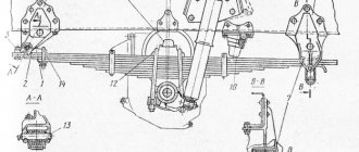
5.1.2 Steering of KamAZ vehicles
5.1.2 Steering of KamAZ vehicles
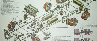
The steering consists of a steering wheel 1, a steering column 2 (Figure 5.6), a cardan transmission 6, an angular gearbox 9, a steering mechanism 10, a hydraulic booster including a control valve 8, a radiator 7, a pump 14 with a reservoir 15 and a steering gear.
Figure 5.6 – Steering control of a KamAZ vehicle
1 – steering wheel; 2 – steering column; 3 – clamp; 4 – flange; 5 – adjusting nut; 6 – cardan transmission; 7 – radiator; 8 – control valve; 9 – angular gearbox; 10 – steering mechanism; 11 – longitudinal steering rod; 12 – bipod; 13 – bipod shaft; 14 – pump; 16 – tank
Steering column 2 consists of a shaft and a pipe. The steering wheel is attached to the upper end of the shaft. The lower end of the shaft is equipped with a groove for attaching the universal joint.
Cardan transmission 6 transmits forces from the steering column shaft to the drive gear of the angular gearbox 9.
The angular gearbox (Figure 5.7) transmits the force from the cardan transmission to the steering gear screw. It is attached to its crankcase with studs. The gear ratio is 1:1.
Figure 5.7 – KamAZ angular gearbox
1 – drive bevel gear shaft; 2 – oil seal; 3 – needle bearing; 4 – drive gear housing; 5, 10 – ball bearings; 6 – adjusting shims; 7 – driving bevel gear; 8 – sealing ring; 9 – retaining ring; 11 – driven bevel gear; 12 – thrust cover; 13 – gear housing; 14, 16 – bearing fastening nuts; 15 – lock washer
Shaft 1 with drive gear 7 is installed in the housing on ball 5 and needle bearings 3. On the shaft, the ball bearing is fixed with a nut 16, the thin edge of which is pressed into the groove of the shaft. The needle bearing is secured with a retaining ring. The driven gear 11 is installed in the gearbox housing 13 on two ball bearings 10, secured by a nut 14 with a lock washer 15. Axial forces are perceived by the thrust cover 12 and the locking ring 9. The driven gear 11 is connected to the screw by splines, which allows it to move relative to the gear. In this case, the hydraulic booster spool mounted on the shaft can move relative to the housing. The meshing of the gears is regulated by changing the thickness of the spacers 6.
The KamAZ steering mechanism (Figure 5.8) has two working pairs: a screw 37 with a nut 38 on circulating balls 40 and a piston-rack 34 meshed with the toothed sector 63 of the bipod shaft. The steering gear ratio is 20:1. The steering mechanism is attached to the left bracket of the front spring and is connected to the steering column shaft by a cardan shaft having two hinges.
The steering gear housing 33 is also a power steering cylinder in which the piston-rack 34 moves. The teeth of the rack and bipod shaft sectors have a variable thickness along the length, which makes it possible to adjust the engagement gap by means of axial movement of the bipod shaft; the shaft itself rotates in a bronze bushing 64, pressed into the crankcase. The axial position of the bipod shaft is set by the adjusting screw 55, the head of which fits into the hole of the bipod shaft and rests on the washer 62. The axial movement of the adjusting screw after assembly should be in the range from 0.02 to 0.08 mm, it is limited by the adjusting washer 61 and the lock ring 60.
A ball nut 38 is inserted into the piston-rack, which is secured with set screws 28, drilled after assembly. Two stamped grooves 39 are inserted into the groove of the ball nut, connected by two holes with its screw groove. In the screw grooves of the screw 37 and nut 38, as well as in the grooves installed in the groove of the nut 38, there are balls that, when the screw is turned, roll out from one end of the nut, return through the grooves to its other end.
The steering gear screw 37 has splines in the middle part on which the driven gear 19 of the angular gearbox sits freely, rotating in two ball bearings.
Figure 5.8 – KamAZ steering mechanism
1 – front cover; 2 – jet plunger; 3 – control valve; 4 – spring of reaction plungers; 5, 7, 21, 24, 26, 31, 41, 48, 52, 58, 59 – sealing rings; 6 – adjusting shims; 8, 15, 22, 45, 60, 66 – thrust rings; 9, 17, 62, 68 – thrust washers; 10, 20 – ball bearings; 11, 43, 54, 56 – nuts; 12 – shaft with drive gear; 13 – needle bearing; 14, 65, 67 – oil seals; 16 – protective cover; 18 – drive gear housing; 19 – driven gear; 23, 64 – bushings; 25, 27 – spacer rings; 28 – setscrew; 29 – bypass valve; 30 – cap; 32 – back cover; 33 – steering gear housing; 34 – piston-rack; 35 – magnetic plug; 36 – plug gasket; 37 – screw; 38 – ball nut; 39 – gutter; 40 – balls; 42 – thrust cover; 44 – lock washer; 46 – gear housing; 47 – thrust bearing; 49 – safety valve; 50 – spring; 51 – spool; 53 – spring washer; 55 – adjusting screw; 57 – side cover; 61 – adjusting washer; 63 – gear sector of the bipod shaft.
The housing 3 of the control valve is attached to the housing 46 of the angular gearbox with studs. Valve spool 51 and thrust roller bearings 47 are secured to the steering gear screw with a nut 54, the thinned edge of which is pressed into the groove of the screw. A conical spring washer 53 is placed under the nut, ensuring uniform compression of the thrust bearings. The concave side of the washer is directed towards the bearing. The large roller bearing rings face the spool.
Spool 51 and screw 37 can move axially 1.1 mm in each direction from the middle position, since the length of the spool is greater than the length of the hole for it in the valve body. They return to the middle position under the action of springs 4 and reaction plungers 2, which are pressed by oil coming from the high pressure line.
High and low pressure (drain) hoses are connected to the control valve body from the power steering pump. According to the first, the oil leaves the pump, and according to the second, it returns.
When the screw 37 rotates in one direction or another, due to the resistance that arises when the wheels turn, a force is created that tends to move the screw in the axial direction in the corresponding direction. If this force exceeds the pre-compression force of the springs 4, the screw moves and displaces the spool 51. At the same time, the pressure in one of the cavities of the control valve and the hydraulic booster increases.
The oil flowing from the pump into the cylinder puts pressure on the piston-rack, creating additional force on the steering bipod sector, and thereby contributes to the rotation of the wheels.
The pressure in the working cavity of the cylinder increases with increasing resistance to wheel rotation. At the same time, the pressure under the reaction plungers 2 increases. The screw and spool, under the action of the springs 4 and the reaction plungers 2, tend to return to the middle position.
The greater the resistance to turning the wheels and the higher the pressure in the working cavity of the cylinder, the greater the force with which the spool tries to return to the middle position, as well as the force on the steering wheel. If the force on the steering wheel increases with increasing resistance to turning the wheels, the driver develops a “feeling of the road.”
When the rotation of the steering wheel, and therefore the movement of the piston, stops, the oil entering the cylinder acts on the piston-rack with a screw and moves the spool to the middle position, which reduces the pressure in the cylinder to the amount necessary to keep the wheels in the rotated position.
The control valve body contains a ball check valve 6, which connects the high pressure and drain lines when the pump is not running. In this case, the steering mechanism works like a regular steering mechanism without power steering. In addition, the valve body has a safety ball valve 8, connecting the high and low pressure lines at a pressure of 6.5-7.0 MPa (65-70 kgf/cm2) and thereby protecting the pump from overheating during operation of the hydraulic booster at this pressure .
The cavities of the control valve and bevel gear are connected to the drain and sealed at the ends with rubber rings 48 and 41 of circular cross-section. All fixed connections of the hydraulic booster are sealed with similar rings.
The bipod shaft is sealed with an oil seal 65 with a thrust ring 66, which prevents the cuff from turning out under high pressure. The outer oil seal 67 protects the bipod shaft from dust and dirt.
The piston in the cylinder is sealed with a fluoroplastic ring 26 in combination with a spacer ring 27. The steering gear screw 37 is sealed in the bevel gear housing with a spacer 25 and a rubber ring 24. The adjusting screw 55 of the bipod shaft is sealed with a rubber ring 59 of round section.
The seal of the drive shaft 12 with the angular reducer gear is combined and consists of two oil seals 14, which are secured against axial movement by a split thrust ring 15.
In the steering gear housing there is a plug 35 with a magnet that catches steel and cast iron particles from the oil.
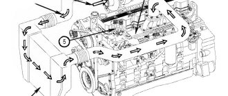
When moving in a straight line (Figure 5.9), spool 11 of control valve 12 is held in the middle position by springs. The oil supplied by the pump passes through the annular slots of the control valve, fills the cavities of the cylinder and is drained through the radiator 15 into the tank. As the rotor speed increases, the intensity of circulation and heating of the oil in the hydraulic booster increase. Bypass valve 10 limits oil circulation. With an increase in oil flow, a pressure difference is created at the end surfaces of the valve due to an increase in the resistance of the calibrated hole K (Figure 5.10). When the force from the pressure difference on the valve exceeds the force of the spring, it will move and connect the discharge cavity of the pump to the tank. In this case, most of the oil will circulate along the pump-tank-pump circuit.
Figure 5.9 – KamAZ steering diagram
a – schematic diagram; b – when turning right; c – when turning left; 1 – steering wheel; 2 – steering column, 3 – driveshaft; 4 – bevel gear; 5 – steering gear housing; 6 – screw; 7 – ball nut; 8 – bipod shaft with gear sector; 9 – piston-rack; 10 – bypass valve; 11 – spool; 12 – control valve; 13 – thrust bearing; 14 – safety valve; 15 – oil cooler; 16 – low pressure oil line; 17 – high pressure oil line; 18 – power steering pump
When the steering wheel is turned, the force is transmitted through the cardan transmission, the angular gearbox, to the steering gear screw.
If significant effort is required to turn the wheels, the screw, screwing into the nut (or unscrewing from it), will displace the thrust bearing and spool, moving the plunger and compressing the centering springs. The displacement of the spool in the body changes the cross-section of the annular slots associated with the cavities of the cylinder. Reducing the cross-section of the drain gap with a simultaneous increase in the amount of oil due to an increase in the cross-section of the injection gap leads to an increase in pressure in one of the cavities of the cylinder. In the other cavity of the cylinder, where the change in cross-sections of the slots is opposite, the oil pressure does not increase. If the difference in oil pressure on the piston creates a force greater than the resistance force, then it begins to move. The movement of the piston through the rack causes rotation of the sector and then, through the steering drive, rotation of the steered wheels. Continuous rotation of the steering wheel maintains the displacement of the spool in the housing, the difference in oil pressure in the cylinder cavities, the movement of the piston and the rotation of the steering wheels.
The KamAZ power steering pump (Figure 5.10) with a reservoir is installed in the camber of the cylinder block. The tank with the filler cap and filter is screwed to the pump body. The tank cover is bolted to the filter stand. The joints of the cover with the bolt and the body are sealed with gaskets. A safety valve is installed in the lid, limiting the pressure inside the tank. The oil circulating in the hydraulic system of the amplifier is cleaned in a strainer. There is an oil level indicator in the filler plug.
The pump is driven by a gear, from a block of distribution gears. Gear 1 is secured to pump shaft 5 with a key 6 and a nut 2 with a cotter pin 3.
The pump is a vane type, double-acting, i.e., in one revolution of the shaft, two complete suction and two discharge cycles are completed. The pump rotor 38 has grooves in which the blades 33 move. The rotor is installed inside the stator on the pump shaft 5 on splines, the rotor fits freely on the splines.
The position of the stator 35 relative to the pump housing 37 is fixed, i.e. the direction of the arrow on the stator coincides with the direction of rotation of the pump shaft.
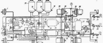
Figure 5.10 – KamAZ power steering pump
1 – drive gear; 2 – gear fastening nut; 3 – cotter pin; 4, 15, 27 – washers; 5 – pump shaft; 6 – segment key; 7 – thrust ring; 8 – ball bearings; 9 – oil sump ring; 10 – thrust ring; 11 – oil seal; 12 – needle bearing; 13 – filler plug; 14 – filler filter; 16 – bolt; 17, 34, 36 – sealing rings; 18 – filter stand; 19 – safety valve; 20 – tank cover with a spring; 21 – cover gasket; 22 – pump reservoir 23 – segment filter; 24 – pump manifold; 25 – tank tube; 26 – fitting; 28 – manifold gasket; 29 – sealing gasket; 30 – pump cover; 31 – bypass valve assembled with a safety valve; 32 – distribution disk; 33 – pump blade; 35 – pump stator; 37 – pump housing; 38 – pump rotor; 39 – ball; K – calibrated hole.
When the pump shaft rotates, the blades are pressed against the curved surface of the stator under the action of centrifugal force and oil pressure entering through the channels in the distribution disk 32 under the pump blades. Cavities of variable volume are formed between the blades, which are filled with oil coming from the suction cavities of the distribution disk. In the suction cavity, oil enters from the cavity of the pump housing 37 through the channels in the stator 35. As the inter-blade volume decreases, the oil is forced into the discharge cavity through the channels in the distribution disk 32.
The end surfaces of the housing and distribution disk are carefully ground. The presence of nicks and burrs on them, as well as on the rotor, stator and blades, is unacceptable.
A tank 22 for oil is installed on the pump, closed with a cover 20, which is secured with a bolt 16. Underneath it there is a washer 15 and a rubber ring 17, which, together with the rubber gasket 21, seals the internal cavity of the tank. A safety valve 19 is screwed into the tank lid, limiting the pressure inside the tank. All oil returning from the hydraulic booster to the pump passes through a strainer 23 located inside the reservoir.
The pump has a combination valve located in the pump cover 30. This valve consists of two valves - safety and bypass. The first, placed inside the second, limits the oil pressure in the system to 7.5-8.0 MPa (75-80 kgf/cm2), and the second - the amount of incoming oil supplied by the pump to the hydraulic booster when the engine crankshaft speed increases.
With an increase in oil supply to the hydraulic booster system (as a result of an increase in the engine crankshaft speed), the pressure difference in the pump discharge cavity and the hydraulic booster discharge line increases due to the resistance of hole K, and consequently, the pressure difference at the ends of the bypass valve also increases. At a certain pressure difference, the force tending to move the valve increases so much that the spring is compressed, and the valve, moving to the right, communicates the discharge cavity with the tank. Thus, further increase in oil flow into the system almost stops.
To prevent noise during operation and reduce wear of pump parts at high engine speeds, the oil, which is bypassed by valve 31, is forced back into the cavity of the pump housing and suction channels. For this purpose, a manifold 24 is used, in which the internal channel communicating with the cavity of the bypass valve has a small flow area, which further expands. This leads to a sharp increase in the flow rate of oil transferred into the suction cavity of the housing and creates a slight increase in suction pressure.
The radiator is designed to cool the oil circulating in the hydraulic booster. The radiator in the form of a double-bent finned tube made of aluminum alloy is secured in front of the radiator of the engine cooling system with strips and screws.
The hydraulic booster units are connected to each other by high and low pressure hoses and pipelines. High pressure hoses have a double internal braid; Tips are installed at the ends of the hoses.