02/02/2022 33,860 KAMAZ
Author: Ivan Baranov
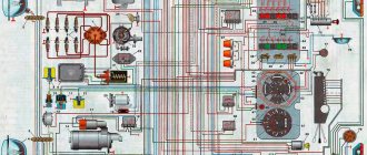
The KAMAZ-5320 electrical circuit diagram is colored, as a rule, it is used to repair electrical wiring and vehicle devices. Thanks to the electrical circuit, the car owner can find failed or faulty components for further repair or replacement. You can learn more about the features of electrical equipment, its malfunctions and diagnostics from this material.
[Hide]
Instrumentation system
As you might guess from the name, this system is designed to service various instrumentation, indicators and sensors. Instruments are located on the dashboard of the car, and sensors are located in its various components and mechanisms.
The electrical diagram of this system is as follows:
The numbers on the diagram indicate:
- fuel level indicator;
- fuel level sensor;
- fuse 13.3722 (7.5 A);
- coolant temperature indicator sensor;
- coolant overheat sensor;
- emergency oil pressure sensor;
- oil pressure indicator sensor;
- oil pressure indicator;
- 11 — blocks of warning lamps;
- coolant temperature gauge;
- generator;
- tachometer;
- speedometer;
- speedometer sensor;
I. to the instrument and starter switch
Warning light circuit diagram
Light signals serve to warn drivers of other vehicles about maneuvers being performed. When turning, overtaking and braking, various light signs are used. The source of light flux is control lamps and LEDs.
Light signaling includes the following elements:
- emergency alarm;
- indication of car and trailer turns;
- brake system alarm;
- external and internal lighting network;
- center differential locking alarm.
Activating the emergency mode button after starting the starter causes the front and rear turn indicators to turn on. In emergency mode, the indicators light up in flashing mode.
Electrical circuit of the lighting unit
Internal and external lighting are designed for vehicle operation in conditions of poor visibility and at night.
The KamAZ vehicle lighting circuit includes the following elements:
- lights on the control cabin;
- halogen fog lights;
- front and rear light indicators;
- underhood incandescent lamp;
- luggage compartment lighting lamp;
- bed lighting lamp;
- instrument panel lighting lamp unit;
- shades with lamps in the control cabin.
Connection of indoor and outdoor lighting is carried out using a single-wire circuit. Uninterrupted operation of the electrical circuit is ensured by fuses with a fuse-link type PRS-10.
The lighting operates using a combination switch directly connected via an ammeter to the power source.
More serious electrical problems
The KamAZ 65115 Euro 3 electrical circuit may also include other, more serious problems, which may be much more difficult to identify and eliminate.
| Problems | What to do |
| If a device fails, the first thing you should do is check the corresponding fuse. | The element may fail due to normal wear and tear or due to voltage surges in the vehicle's electrical system. If the fuse has been replaced recently, you should make sure there are no changes. |
| A separate element of electrical equipment may also fail. | For example, if diagnostics of a non-working heater or headlights does not reveal damage or short circuits in the corresponding electrical circuits, the reasons may lie in the breakdown of the stove itself or the burnout of one of the light bulbs. Such problems happen quite rarely, but you should be prepared for them. |
| Lack of functionality of all electrical equipment at once. | This may indicate that the battery is completely discharged or the level of electrolyte in it is insufficient. In such a situation, you should check the charge level and amount of liquid in the cans. |
Another real problem with the electrical system is the complete or partial inoperability of the generator. Considering that this component ensures the functioning of all electrical units when the truck or dump truck is moving, its malfunction can be noticed immediately. A lack of voltage in the electrical network may be associated with weak belt tension - in this case, a simple tightening of the belt may be sufficient to solve the problem. In case of more serious troubles, such as wear or breakdown of certain components of the device, dismantling and complete repair of the generator unit is required.
Certain problems, such as current leakage or lack of contact, are most often associated with violations of the electrical wiring insulation, including its breaks, oxidation or burnt contacts, etc. When replacing wiring, it is recommended to first make additional insulation of the new cable.
How to determine the malfunction?
Detecting breakdowns in equipment operation is possible with the involvement of a specialist or at home.
In general, there are two vehicle conditions in which a circuit failure can be determined:
- The engine does not start and the vehicle cannot be operated. There can be many reasons for the breakdown in this case. Equipment diagnostics should begin by checking the ignition switch, switchgear, spark plugs, high-voltage wires, starter assembly and, of course, the battery. In most cases, the cause can be solved by charging the battery, cleaning the spark plugs from carbon deposits, or replacing high-voltage wires. In addition, the reason may be a failed generator. Before you begin dismantling and disassembling the unit, you should check the quality of the generator belt tension. Perhaps the strap is loose or its tension is very strong, which is also not very good for the car.
- The engine can be started, but the equipment does not work or only works partially. A group of devices may not be working. For example, in your car the turn signal and windshield wiper blades stopped working at the same time. It would seem, how can these devices be connected to each other? But you need to take into account that these two systems operate from the steering column switch. And if it fails or there is a bad contact on its circuit, then the nodes simply cannot be started. If the engine starts, then some of the components do not work, then you should first check the fuses in the block; it is quite possible that one or part of them has simply blown. If the safety elements are working, and you are 100% sure that the electrical equipment is working, then you need to start diagnosing the wiring (the author of the video is the CarEnergy channel).
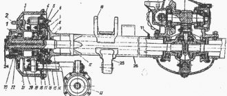
Fuses and relays for vehicles with Euro-4 class engines
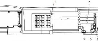
Location of fuses and relays
1 – Relay behind the switch panel; 2 - fuse block (F2, F3, F4, F6); 3 – relay block; 4 - fuse F1; 5 – starter relay; 6 – alarm relay; 7 – windshield wiper relay; 8 – turn signal interrupter relay.
Relay behind switch panel
1, 2, 3, 4 - See the Table of applied relays; 5- fuel heating relay; 6 - ECU relay; 7 — relay for daytime running lights; 8 — platform stop sensor relay; 9 — rear fog lamp relay; 10 - oil separator relay
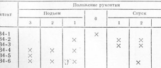
| Pos. | For Cummins engines | For KAMAZ engines |
| 1 | ABS relay | |
| 2 | Starter Interlock Relay | ABS relay |
| 3 | Brake relay | |
| 4 | Clutch relay | Secondary Brake Relay |
Fuses and relays for vehicles with Euro-4 class engines
Location of fuses and relays
1 – Relay behind the switch panel; 2 - fuse block (F2, F3, F4, F6); 3 – relay block; 4 - fuse F1; 5 – starter relay; 6 – alarm relay; 7 – windshield wiper relay; 8 – turn signal interrupter relay.
Relay behind switch panel
1, 2, 3, 4 - See the Table of applied relays; 5- fuel heating relay; 6 - ECU relay; 7 — relay for daytime running lights; 8 — platform stop sensor relay; 9 — rear fog lamp relay; 10 - oil separator relay
History of appearance
Initially, the KAMAZ 5320 with a 6x4 wheel arrangement appeared in the production program of the Kama Automobile Plant, which became the platform for subsequent modifications:
- On its basis, KAMAZ 53215 appeared in 1979. Both models had a noticeable difference - the cabin was equipped with a berth;
- Since 2008, a number of components and assemblies have been installed on the KAMAZ 65117, although it is not a direct successor to the KamAZ 5320 model (see wiring diagram), however, the wiring diagram of the KAMAZ 65117 is in many ways similar to the 53215 model;
Factory photo KAMAZ 53215
- For the needs of the Soviet army, since 1979, the production of model 4310 with a 6x6 wheel arrangement (all axles, including the front axle) has been mastered. At the customer's request, the KAMAZ 4310 electrical wiring had a different design - sealed, shielded.
Varieties
There are several types of these mechanisms:
The KamAZ starter belongs to the first type of device. This mechanism is the most powerful, since here the transmission of torque from the armature to the gear is carried out by a gearbox. Such starters have not only high power, but also good starting torque. They also have a long service life. These types of starters are used on 90 percent of modern cars.
As for gearless elements, they operate as follows. After voltage is applied to the electromagnetic switch, the Bendix gear moves and engages the flywheel ring. Current flows to the armature. Rotation occurs. The gear and shaft are aligned using a freewheel. After the engine has started successfully, this connection is released. The current supply stops and the gear returns to its original position. Due to low efficiency and low maintainability, gearless elements are practically not used in the automotive industry.
Read more: Niva spare wheel cover
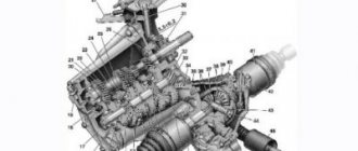
Power supply system for KamAZ-43118 vehicle
This system, perhaps, can be considered the main one in the car; thanks to this system, the truck is supplied with electricity when the power unit is running. The general diagram of the power supply system is presented below:
In the figure the numbers indicate:
- generator excitation winding cut-off relay;
- generator;
- fuse box;
- starter relay;
- starter;
- rechargeable batteries;
- mains switch;
- button for remote battery disconnect switch;
- heater motor relay;
- ammeter;
- fuses 13.3722 (7.5 A);
- fuse PR310 (10 A);
- instrument and starter switch;
I. to the EFU thermal relay
Brief explanations of the diagram:
The energy sources for this system are a generator (2) and two batteries connected in series (6). The negative terminal of the batteries, as in all cars, is connected to the housing. But, unlike passenger cars, on KamAZ it is connected through a special ground switch (7), which has a remote control.
Number 1 in the diagram shows a relay for disconnecting the generator excitation winding. This relay must break the circuit when the electric torch device (EFD), which is responsible for starting the engine in the cold season, is operating.
When the engine is running and the ignition is on (the ignition unit is indicated in the diagram as number 13), the circuit leading to the remote battery mass switch button (8) is opened. This is done so that the engine does not spontaneously turn off accidentally or as a result of a malfunction.
Let's look at the light signaling circuit next:
Features of the driver's seat
In comparison with other trucks, the KAMAZ generation immediately became the standard for an organized driver’s seat:
- Thanks to the new comfortable cabin;
- Modern governing bodies;
- Improved lighting devices that meet the requirements for freight transport operating in off-road city conditions;
- An efficient heating system for the cabin in general and the driver's seat in particular.
KAMAZ 6520 wiring diagram: interior configuration, borrowed from on-board models
For reference: That is why the automaker used the same cabin concept on all modifications without exception, including flatbed, tilt and body versions of the cargo platform with a 6x4 wheel arrangement. Thanks to this, the selling price of the car remained the same.
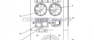
Fuse F5
Fuse F5 is installed on the front panel of the cab.
Fuse F5 1 - To fuse block F4; 2 - fuse F5; 3 - jumper; 4 — “Generator-fuse” wire; 5 — wire “Battery - fuse”; 6 - fuse wire; 7 - to fuse block F1; 8 - fuse wire
You can fix everything yourself
KAMAZ trucks are equipped with a St-142b starter with a voltage of 24V and an idle current of up to 130 Amperes. To start it, you need to turn the key to a non-locking position. As soon as the start has taken place, the key is released.
Its action goes like this:
- The current from the batteries passing through the traction relay engages the flywheel ring gear and the drive gear while simultaneously closing the starter power contacts.
- rotation of the armature is created with transmission of torque to the flywheel through the drive gear.
- they are disconnected after the engine begins to operate in autonomous mode.