05/08/2020 598 Electrical wiring and electrical circuits
Author:Ivan
The electrical circuit of the UAZ “Loaf” injector 409 is based on the design of cars of previous modifications, but has its own characteristics. Modern cars received an injection engine, which improved dynamics and increased fuel efficiency.
[Hide]
Technical characteristics and design features of the ZMZ 409 engine
The ZMZ 409 gasoline engine, equipped with a microprocessor-controlled direct injection system, is based on the cast-iron cylinder block of the ZMZ 406 model unit. The power plant was created specifically to equip UAZ vehicles, as well as Volga (experimental and small-scale versions). It differs from the base engine by an increased piston stroke and modernized pistons, which made it possible to retain the same connecting rods. Depending on the software version, the motors meet Euro 2/3 or 4 requirements. The latest modifications of the motor comply with Euro 5 standards and have modified power and torque curves.
The powertrain serial number, which is the vehicle's VIN number, is located on the left side of the engine block above the front mount mount.
Technical characteristics of the power unit:
- block design - 4-cylinder in-line;
- number of valves per cylinder - 4 (2 for intake, 2 for exhaust);
- cylinder diameter - 95.5 mm;
- piston stroke - 94 mm;
- working volume - 2693 cubic meters. cm;
- compression ratio - 9;
- The order of flashes in the cylinders is 1:3:4:2;
- maximum power (version for UAZ “Bukhanka”) - 112 hp. With. at 4250-4400 rpm;
- torque - no less than 198 N/m at 2500 rpm;
- fuel type - unleaded gasoline with an octane rating of 92 or more;
- direction of rotation of the crankshaft (from the pulley side) is right;
- type of cooling system - liquid, forced type;
- crankcase ventilation system - forced, closed type, operates from a vacuum inside the intake manifold;
- engine weight (with attachments) - 190 kg.
Main features of the engine design:
- the working mirrors of the cylinders are made directly in the material of the cast iron block, without the use of liners;
- main bearing caps are not interchangeable, since the parts are processed together with the block;
- the front cover of the camshaft supports is the same for the intake and exhaust;
- the timing gear bearing caps are machined together with the head, so they cannot be swapped;
- Hydraulic play compensators are installed in the valve drive;
- some engines have intake and exhaust camshafts with identical cam profiles;
- the pistons have recesses on the bottom that prevent contact with the valves in the event of a violation of the valve timing;
- the valves and mounting springs are identical to those used on the engines of the VAZ-2108 car.
To complete the UAZ “Bukhanka” vehicles, several engine modifications were supplied, differing in attachments.
Unit repair and maintenance
Signals for repairs can be:
- Oil leak.
- Increased noise and vibration.
- Difficulty switching from one position to another.
- Spontaneous loss of the switched on operating mode.
Although often, to fix problems, it is enough to just adjust the fasteners or lubricate problem areas and points. If this does not help, the car must be driven into an inspection pit or overpass, after which technological operations must be carried out in strict sequence.
Source
Varieties of electrical wiring diagrams for the “Loaf”
Early cars used a carburetor engine, which in modern versions is replaced by an injection engine. The external lighting equipment has changed, disc mechanisms have appeared in the braking system (front) and an anti-lock braking system (ABS) has been installed.
The Ulyanovsk plant produced early versions of the bus with all-wheel drive (model 452) and only with a rear drive axle (451D). The electrical components of the machines were identical.
A simple circuit in which there is no electronic carburetor control unit
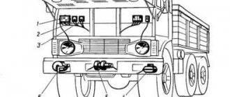
Purpose of elements on early versions of the carburetor minibus UAZ 451M and 452:
- Lead-acid battery with a voltage of 12V.
- Engine starter.
- Additional relay for starting the starter.
- Voltage regulator.
- Generator.
- Central switch for external lighting.
- Foot switch for selecting the operating mode of the headlights.
- A front light that functions as a side signal and a direction indicator.
- Headlight.
- Instrument cluster.
- Left turn signal indicator.
- Current meter in the on-board network.
- A device for displaying the amount of gasoline in the tank.
- Coolant temperature gauge.
- Lubrication system pressure gauge.
- Right turn signal indicator.
- Speedometer installed separately from other instruments.
- High beam indicator lamp installed in the speedometer.
- Fan drive motor for driver. The device was installed only on tropical machines.
- Fan switch.
- Wiring connecting element.
- A sensor that determines the pressure level in the oil system.
- A measuring element that transmits a signal about the coolant temperature.
- A separate sensor that determines the moment of overheating of the power plant. Based on a signal from the device, a warning lamp on the instrument panel turns on.
- Control indicator for motor overheating.
- Sound signal.
- Alarm button.
- Distributor of high-voltage ignition pulses.
- Lamps for lighting the cabin and rear of the minibus.
- Cabin lighting control.
- Thermal reusable fuse.
- Turn signal control lever mounted on the steering column.
- Interrupting turn signal relay.
- A switch on the brake pedal that controls the operation of the brake lights.
- Spark plug.
- Noise suppression resistor installed in the tip of the spark plug wire.
- Ignition coil.
- Plug connector for connecting additional devices.
- Fuse box.
- An electric motor drives the windshield wipers.
- Windshield wiper operating mode switch.
- Fan drive motor. The device is used to blow windshield.
- Switch for the interior air supply system.
- An ignition switch equipped with a contact group for switching the ignition system and starter.
- Rear lighting control.
- Fuel level sensor installed inside the tank.
- Connection block for wiring.
- Switch for the negative pole of the battery ("ground").
- Rear license plate light.
- A combined signal that includes a lamp for the parking lights and a second one for the brake signal and turn signal.
Electrical diagram of early UAZ 452/451D
Complex circuit with a connected carburetor control unit
Description of the electrical components of the carburetor “Loaf”, produced since the mid-80s (without a block of steering column switches):
- Front right combination lamp.
- Right headlight.
- Fog light on the front of the car (right).
- A similar unit installed on the left.
- Left headlight.
- Front left combination lamp.
- Switch for the control diode for reducing the fluid level in the brake hydraulic system.
- Klaxon.
- Windshield cleaner.
- Stop light switch.
- Steering column switch for direction indicators.
- Electric washer pump.
- Additional heater fan resistor.
- Controller for turning on front fog lights.
- Low beam headlight relay.
- A similar unit for high beam.
- Fuse link for fog light circuit protection (rated 10A).
- Relay for controlling direction indicators and hazard warning lights.
- Headlight mode switch.
- Electric heater fan.
- Cigarette lighter.
- Cigarette lighter circuit fuse (16A).
- Windshield wiper operating mode switch.
- Horn button.
- Control of the lighting system in the cabin.
- 20A thermal fuse.
- Fuse block.
- Plug connector.
- Heater fan speed switch.
- External lighting control button.
- Adjustable resistance of the instrument lighting system.
- Speedometer.
- Voltmeter.
- Pressure gauge.
- Thermometer.
- A device for displaying the amount of fuel in the tank.
- Rear fog lamp control key.
- High beam indicator.
- A lamp showing the operation of the direction indicators.
- Parking brake warning signal.
- Indicator of malfunction of one of the circuits of the service brake system.
- Low pressure lamp in the lubrication system.
- Cooling system overheating warning lamp.
- Egnition lock.
- Carburetor economizer control controller.
- Key to turn off the front fog lights.
- Alarm control button.
- Cabin lighting.
- Generator.
- Oil pressure alarm sensor.
- Sensor of a device indicating the operating pressure in the lubrication system.
- Measuring element in the cooling jacket.
- A device for recording elevated temperatures (in case of overheating).
- Ignition system switch.
- Vibrator, used when the switch fails.
- Limit switch under the parking brake lever.
- Additional resistance.
- Starter start relay.
- Economizer solenoid valve.
- Additional solenoid for unbalance valve.
- Small size valve switch mounted on carburetor.
- Spark plug of the first cylinder.
- A similar element of the second cylinder.
- Third candle.
- Fourth candle.
- Pulse distributor with sensor.
- Coil.
- Side right turn signal.
- Switch for measuring sensors in the left and right fuel tank.
- Starter.
- Battery.
- Negative battery power switch.
- Reverse gear switch including warning light.
- Side left turn signal.
- Fuel quantity meter in the first tank.
- A similar unit for the second tank.
- Rear light on the right side of the car.
- License plate light (right).
- Left room lamp.
- Fog lamp on the rear.
- Reverse warning light.
- Left rear combination lamp.
Diagram of electrical components of the “Loaf” without steering column switches
When using a block of steering column switches on the “Loaf”, the windshield wiper control is placed on it, and a clock is installed on the instrument panel. Otherwise, the electrical wiring diagram remains the same.
Platform for conveyor models
The “Loaf”, which became famous, thanks to its all-metal body, the “452” model served as a platform for the creation of an entire line of vehicles:
- UAZ 2206 – a minibus designed for 11 people;
- UAZ 3962 – vehicle for emergency medical services;
- UAZ 396255 - a civilian modification of an ambulance for the needs of rural areas;
- UAZ 39099 – promoted under the name “Farmer”. Designed for 6 passengers and 450 kg of cargo;
- UAZ 3741 – a van for transporting 2 passengers and 850 kg of cargo;
- UAZ 3303 – an onboard vehicle with an open body;
- UAZ 3904 is a cargo-passenger version that combines the convenience of an all-metal body for passengers and an open body for cargo.
For reference: in all modifications, the electrical wiring of the UAZ 2206 is taken as a basis, from which, for each model, unused components that perform certain functions in the car interior have been removed.
The electrical wiring of the UAZ 3909 is identical to the models 3741, 2206 and 3962
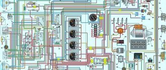
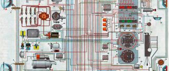
Wiring diagram for "Loaf" with injection engine
Elements of the electrical circuit of the UAZ “Loaf” injector 409 include the following items:
- Front right lamp, consisting of turn signal lamps and side lamps.
- Electric windshield washer pump.
- Windshield cleaner.
- Steering column switch for the operating modes of the cleaner and washer.
- Rear fog lamp control key.
- External alarm button.
- Electric motor for the impeller of the additional heater located in the passenger compartment. The unit is used on some vehicle trim levels, for example, 220695 or 396255.
- Right headlight.
- Additional resistor in the main heater fan circuit (used on all minibuses).
- Electric motor of the main heating and ventilation device.
- Fan operating mode switch.
- Resistor of an additional heating device (installed only in conjunction with item 7).
- Control of the operation of the second heater (optional).
- Fuel module installed inside the tank.
- Right turn signal.
- Rear combination lamp on the right side.
- Sensor for measuring the level of brake fluid in the supply tank.
- Klaxon.
- Controlling the operation of the sound signal.
- Relay for turning on the fog lamp on the rear of the car.
- Switch for operating modes of external light signaling.
- Control indicator block.
- Speedometer.
- Separate safety element in the main heater motor power supply circuit.
- Generator.
- Engine starter.
- Battery 12V.
- Ground wire breaker, installed on parts of cars.
- Rear registration plate illumination lamps.
- Fog lamp on the stern.
- Steering column switch for direction indicators.
- Thermal safety element.
- Instrument cluster.
- Fuel tank selection key. Applicable only to some vehicles; models 330395, 330365 and 390945 are equipped with a single gasoline tank.
- Sensor indicating emergency pressure in the lubrication system.
- Oil pressure measurement sensor (to be displayed with a pressure gauge).
- Starter circuit control relay.
- Lamp indicating reverse gear engaged.
- Brake light limit switch (located near the brake pedal).
- Connection block for wiring.
- Pump motor switch for forced circulation of coolant through the auxiliary heater.
- Electric motor to drive the liquid pump.
- Sensor for signaling that the permissible temperature threshold of the power unit has been exceeded.
- Measuring element for fuel level in the tank.
- Sensor for measuring movement speed.
- Rear combination lamp on the left side.
- Left headlight.
- Contact group for controlling hazard warning lights and direction indicators.
- An end element designed to close the reversing indicator lamp circuit.
- Front left lamp, consisting of turn signal lamps and side lamps.
- Foot switch button for high/low beam headlights.
- Fuse block.
- Socket for supplying power to additional electrical equipment.
- Ignition off.
- Parking brake lever position indicator button.
- Left turn signal.
- Cabin lighting.
- Interior lighting switch.
- Passenger compartment interior lighting lamp.
- Backlight control.
Wiring diagram for UAZ "Loaf" engineer
general information
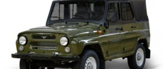
Serial production of the UAZ “Hunter” modification began on November 19, 2003. The predecessors of the car, modifications: 3151, 31512, 31514, 31519, 3153 were produced from 1985 to 2007. The founder who laid down the principles of the all-terrain model, UAZ-469, was produced from 72 to 85. For most fans, the cessation of production of the car in 2014 was unexpected. However, a year later, the creation resumed, only the modification complied with the increased environmental standards of the Euro-5 class.
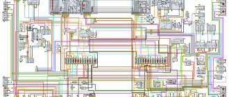
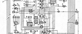
Electrical diagram of UAZ “Hunter” with fuel injection:
The wiring diagram of the UAZ Hunter is made according to the principle of one conductor, the second being the car body. Electrical circuits that control a power plant with several conductors are connected to the core only through the electronic unit. Communication with other consumers occurs through the ignition switch. The combination switch contains an interaction point and a mechanism that prevents theft. The circuit is safe because the on-board voltage does not exceed twelve volts.
The car console is equipped with devices for opening road lights and anti-fog lights. In addition, there are regulators for the operating mode of the electric fan of the stove. The following are combined into a single unit located on the switches under the steering wheel of the car: headlights, turn lamps, glass cleaners, and a cleaning fluid sprayer. Devices that consume more power are connected via electromagnet relays.
Additional elements of the “Loaf” electrical system
The following elements can be installed in the Loaf cabin:
- Fuse block.
- Turn signal control relay.
- ABS indicator lamp controller.
- Turning on the high beams.
- Low beam control relay.
- Ensuring intermittent wiper movement.
- Rear fog lamp controller.
- Starter circuit control.
Arrangement of elements in the cabin
If ABS is used, an additional fuse box is installed on the machine, which includes:
- protective element of power circuits, designed for a current of 40A (position I);
- 25A wiring protection device (position II).
Location of fusible links of the ABS system
Symbols on the diagram:
- Block.
- Direct fuses.
When installing an anti-lock braking system, the following components are included in the electrical circuit:
- hydraulic unit with controller A1;
- sensors for determining the speed of rotation of the front and rear wheels - B1/B2 and B3/B4, respectively;
- acceleration sensor B5;
- ABS control LED on the instrument panel, indicating a system malfunction;
- EBD indicator of hydraulic module failure;
- Brake pedal position sensor BLS.
Schematic diagram of ABS on the “Loaf”
The main fuse box used on cars is:
| Number on the diagram | Denomination, A | Purpose |
| F1 | 10 |
|
| F2 | 10 |
|
| F3 | 10 |
|
Diagram of the main mounting block
Medical versions of the Loaf are equipped with an extended fuse block to protect additional equipment. There are also cars equipped with heated front seats at the factory. These machines have additional wiring harnesses.
Self-installation of electronic ignition on a UAZ was demonstrated by the author of the video, Alexander Grushevsky.
troubleshooting
On any domestic car, problems periodically arise in the operation of electrical equipment. If you notice that the UAZ wiring is not working correctly, you need to diagnose it and check all the elements. If there are any malfunctions in the operation of electronic devices, first of all you need to check whether the fuses in the mounting block have burned out. If everything is fine with these elements, but the equipment still does not function, for example, if we talk about optics, then you need to check whether the light bulbs are working. If the lamps themselves are working, it is necessary to test the electrical part using a tester (the author of the video about testing car wiring is Ramil Abdullin).
If the Loaf refuses to start at all, you need to do the following:
Features of the UAZ 452 electrical circuit
The electrical circuit of the early version of the minibus has its own characteristics related to the purpose of the vehicle. The equipment was supplied to the army and various government agencies. The car could only fall into private hands after being written off. Because of this, the electrical circuit was extremely simple; additional devices were not provided by the factory (except for ambulances).
Electronic components
The wiring is built according to a single-wire circuit; the car body and the crankcases of the units are used as the negative pole. Operating voltage 12 V, all equipment is designed to use direct current. The battery is located behind the back of the driver's seat and is covered with a standard ebonite cover on top. Removing the battery is only possible after the driver's seat is tilted forward.
The electrical equipment included a G12 DC generator equipped with two current-collecting brushes. The device provided a maximum current of no more than 20A at an operating voltage of 12-15V. The PP24-G2 regulator was installed separately from the generator, on the wall of the engine compartment.
Due to the low corrosion resistance of the body, it was necessary to regularly inspect the connection points of the negative terminal from the battery. But the connection points of various equipment are also susceptible to destruction. These same problems were inherited by modern “Loaves”.
Engine compartment
Access to the upper part of the power unit for servicing the ignition system is only possible from inside the bus. On top there is a removable metal casing covered with a layer of heat and sound insulating material. There is no separate lampshade for lighting; for work in the dark, a portable lamp or ceiling lantern is used.
View of the engine after removing the hood
Passive safety
Passive safety at the time the minibus was created was assessed as sufficient. Despite the absence of deformation zones, the driver and front passenger had a good chance of a successful outcome in a frontal accident. But from a modern point of view, passive safety in a car is completely absent. The increase in driving speeds has led to the fact that in the event of a frontal impact, the driver and passenger at least receive severe leg fractures.
On the latest versions of cars produced after 2014, an electronic anti-lock braking system began to be used, which improved braking performance. Until this point, the design of the car lacked any electronic means of passive safety.
External optics
Features of external optics:
- The headlight wiring design uses a mechanical-type central switch that distributes electricity to consumers. The unit was borrowed without changes from the previous generation SUV GAZ 69.
- Lighting elements were borrowed from other UAZ and GAZ vehicles. In turn, the equipment is standardized for Soviet-made cars. This ensured the interchangeability of components and simplified machine repairs.
- The front sidelight with a transparent lens has one double-filament lamp, which is also a turn indicator and a side signal.
- The back of the minibus has round lights with a red lens. Inside there is a two-filament lamp for the brake signal and turn signal (one filament) and the side light (the second).
- There are no side turn signals.
Rework
Actually, the work itself comes down to remaking the distributor, which will no longer have a high-voltage part - an electronic switch will generate high-voltage pulses for it
. The photos below show the location of two sensors at once.
Pay attention to the shape of the contact plate:
- It has curved ends - the sensors are located vertically;
- Flat – the sensors are mounted horizontally.
Both options are working, it all depends on the design of the distributor. In the future, you only have to adjust the ignition. The instructions are simple - you must remember that sparking begins when the edge of the plate is in the center of the Hall sensor.
- Rotate the crankshaft until the piston in the first cylinder reaches TDC;
- Rotate the distributor body until the contact plate is in the sensor slot;
- Carefully tighten all mounting screws to eliminate any play.
- Start the engine.
Precautionary measures
Electrical diagram of a GAZ-3110 car with a ZMZ-4062 engine GAZ 3110 Volga
A UAZ Hunter car, the electrical circuit of which fails if used incorrectly, requires compliance with safety rules.
- Manipulations with the machine related to electrical equipment are carried out with the energy storage battery removed. Disabling and connecting the battery to the circuit is mandatory when the excitation is deactivated;
- Circuit monitoring is carried out without shorting the conductors to the housing; in addition, checking the serviceability of equipment using the “spark” method is prohibited, since it will lead to breakdown of some units; Only safety elements of the established type are used; Replacement of fuses is carried out with non-metal devices to avoid connecting points of the electrical circuit with different potential; You cannot remove the battery from a running power plant, this will damage the voltage regulator and other elements;
- Do not touch conductors with a high degree of electrical potential when the engine is running; Checking the diodes of the rectifying unit with an ohmmeter, as well as with a control lamp, the power supply of which is more than 12V without disconnecting the products from the generating device is excluded; Resistance to the passage of current by the insulating layer of the stator coil of the generating device is checked on a dismantled product from the machine and disconnected from the rectification unit;
- Manipulations with the welding machine on board the UAZ “Hunter” are carried out by first disconnecting the conductors from the battery, as well as disconnecting the terminals of the generating device and controller;
- When charging the battery, the product is disconnected from the vehicle.
Vehicle interior
The changes also affected the interior of the car, making the modification attractive and capable of competing with cars from similar manufacturers. The upholstery, dashboard, as well as the electrical circuit of the interior have changed.
UAZ “Hunter”, instrument panel:
- A new, informative instrument panel has been installed;
- Electric window lifts installed;
- Electrical diagram of the UAZ Hunter 315195 injector includes a relay that protects fuel injection. An electric glass and rear door wiper is installed;
- A new type of fuses are used to protect twenty-six vehicle circuits.
Equipment replacement
If you decide to replace the heater yourself, you should first familiarize yourself with the UAZ Bukhanka stove diagram to connect the electrical component. It is not difficult to install the equipment itself, securing it in the conventional engine compartment located inside the car. But even here you should adhere to certain rules and recommendations. The process will be considered using the example of using NAMI equipment, which has better performance and also boasts the presence of a cabin filter, which is not present in the standard Bukhanka heater.
- The first step is to drain the antifreeze from the system and also disconnect all existing wiring. To make it easier to reassemble and connect, you can write down all your steps or mark the wires, pipes and hoses;
- You need to disconnect the console from the shield, then remove the heating unit, remove the air intake flap, remove the seal and thoroughly clean all existing open recesses;
- Take measurements under the air filter, placing its housing against the surface. Next, make several mounting holes. Just don't use a drill with a diameter larger than 3.2 millimeters;
- At the installation site, apply a layer of high-quality automotive universal sealant that is resistant to moisture and sudden temperature changes. Make the layer large enough. Install the filter housing and secure it. The filter itself can already be inserted into its mounting slot;
- A new heater is being installed in the interior. It is fixed with studs, nuts and an M6 bolt. Secure everything as securely as possible;
- Then the console is installed, the entire structure is mounted on self-tapping screws;
- Then you can start connecting the control rod and fixing it;
- Connect all pipes through which antifreeze passes. For reliability, it is recommended to tighten them with clamps;
- Don’t forget about the channels that allow you to blow on the windows, avoiding them from fogging when the car is used in conditions of high humidity or precipitation. Every car should have windshield defrost. Be it a latest generation Mercedes or the good old Bukhanochka produced by UAZ;
- The installation is completed by connecting the electrical component. There is a connection diagram here that is worth considering separately.
In reality, there is nothing particularly difficult about changing the standard heating system on Bukhanka and installing more efficient and productive equipment in place of the old stove.
Electrical connection diagram
The system will not be able to operate and heat your Loaf if it does not receive power. There is a special scheme for connection. By acting consistently and carefully, you will be able to power your new stove without any outside help and enjoy the efficient operation of the heater.
- To begin, choose a location to place the mass. The black wire is responsible for ground. It is fixed on any metal surface convenient for you. It is best to do the mass on the body;
- Next comes the positive wire. When connecting it, first disconnect the minus from the battery so that the machine is not under voltage during the work;
- Plus it is recommended to enclose in a corrugated casing. Then the wire is pulled to the safety block, that is, to the block on the Loaf;
- Please note that on a car there are 4 fuses in its block. The last one, that is, the fourth one, is constantly under voltage. You should connect to any of the first three. Just make the connection from above, in front of the standard fuse in the block;
- In principle, at this point the connection of the electrical circuit can be considered complete. Be sure to first check the functionality of the furnace equipment.
We can say with confidence that the heating system used on UAZ Bukhanka vehicles has a fairly simple design and layout
Therefore, experienced motorists who are accustomed to doing maintenance, repairs and some modifications with their own hands should not have any problems understanding the Bukhanka heater. But it is extremely important to constantly monitor its performance, carry out preventive measures, and monitor the condition and amount of coolant. Pay special attention to the weakest points of the stove.
The owners of Bukhanok themselves include standard faucets among them. The faucet often turns sour, jams and leaks. This is due to the long downtime of the faucet, which drivers simply forget to periodically open, purely for preventive purposes.