Electrical diagram of URAL-5557
24 Oil filter clogging sensor 68 11.3704000-01 Push-button switch 4 11.3741060 Fuel heater URAL 5557 47 11.7904000 Condenser filter 78 1101.3816010 Tire pressure gauge 34 1102.3741 Solenoid valve 3 1 1112.3740 Torch spark plug 27 1112.5208000 Windshield washer 44 12.3741000 Additional resistor with electrothermal relay 23 13.3839600 Air filter clogging sensor 22 1322.3771000 Generator 113 1402.3737000 Ground switch 59 16.3730000 Windshield wiper motor 83 16.3802010 Speedometer 11 17.3723000 Connecting panel 127 171.3711010 Spotlight 89 1 901.3830010 Pressure indicator 105 2109.3704010-30 Ignition switch 55 211.3777 Rear fog lights relay 88 2212.3803-13 Cross-axle differential lock indicator 87 2212.3803 -20 Air filter clogging indicator 91 2212.3803010-16 Battery charging indicator 36 25.3708000-30 Starter 81 2531.3813010 Electronic tachometer 29 2602.3829010 Emergency oil pressure sensor 38 264.3712010 Front lamp barite 118 2702.3829010 Sensor for air pressure drop in cylinders 50 2802.3829010 Sound signal switch 46 29.3722000-01 Bimetallic fuse 74 32.3710000 Hazard warning light switch 115 375-3724070 Wire from starter to MOUNT assembled 69 3812.3710.02.04 Rear light switch 73 3842.3710.11.04 Rear fog light switch 39 431.373 1010-01 Side marker light 6 4320-3724082 Heater wire bundle 106 4320-3724098 Wire from the parking brake switch to the control lamp block assembly 15 4320-3724138 High voltage wire with noise suppression resistance 9 4320-3724140-01 High voltage wire for the heater 14 4320-3724170-10 Wire to the side repeater assembly 63 432 0- 3724175-10 Wire of road train sign assembly 116 4320-3724283-01 Wire from ground switch to socket 110 4320-3724284-01 Wire from battery to socket 82 43202-3724290-11 Wire connecting devices to ground 57 4320 X- 3724133 Wire bundle for headlight range control 92 4320Х-3724137 Wire bundle for wheel lock indicators 60 4320Х-3724167-10 Wire bundle for windshield wiper 28 4320Х3724102 Wire bundle for engine fan clutch 95 4320Х3724139 Wire bundle for sensor inclusion BMKD 45 4320Ya2-3724010-40 Main wire bundle assembled 18 4602.3710010 Switch 20 5102.3709010 Fan clutch switch 12 511.3726010 Side turn signal repeater 121 5202.3827010 Fuel level indicator sensor 117 5557-3724070-30 Battery connection wire 114 55 57-3724080-10 Wire connecting batteries with ground switch 64 55571Х-3724020- 30 Additional bundle of wires 124 55571Х-3724040-10 Bundle of wires for rear signal lights 119 55571Х-3724145 Bundle of wires to the emergency pressure sensor 94 5557Х-3724035 Bundle of wires rear 112 557-3724050 Wire from the battery to the starter 25 661 .3710-01 Thermal relay 2 671.3711010 Headlight assembled URAL 5557-40 51 6TB.266.002 Plug socket type 47K 53 733.3747000-10 Buzzer 48 738.3747000-20 Starter relay 123 7442.3716010-10 Rear lamp 8 90.3747010 Relay main beam headlights 10 9301.373401 High voltage source 80 AP171A-3811010 Ammeter 99 VK12B- 3720000 Hydraulic stop light switch 71 VK343-3709000-01.08 Lamp switch 72 VK343-3709000-02.16 Road train sign switch 108 VK403A-3716000 Parking brake warning switch 96 VK416B-3709000 -01 Instrument panel light switch with rheostat assembly 100 VK503-3710110 Brake system fault warning switch 16 VN-45M Valve switch 109 ILAE.563414.011 Battery 26 KEM 32-23 Solenoid valve 30 MM370-3829010 Oil pressure sensor 37 MMMM.306577.004 Engine stop solenoid valve 65 ME226V-3 730000 Heater electric motor 3 ME252-3730000 Electric motor heater 101 P110-3709000-A Turn signal switch 70 P147-370900-03.11 Cab heater switch 102 P147-3709000-07.09 Windshield wiper switch 75 P305-3709010-0 Light switch 52 P39A-3710000- 0 Foot switch for headlights 79 PD511E-3803010- U-HL Right indicator lamp unit 86 PD512E-3803010-U-HL Left indicator lamp unit 5 PZhD30-1015500-04 Electromagnetic valve with nozzle and electric heater assembly 58 PR119-3722000-01 6A fuse 76 PR119B-3722000-0 1 Fuse fusible 10A 67 PR120-3722000 Fuse block 111 PS315-3723100 External starting socket (position 33) 125 PS325-3723100 Plug socket 126 PS326-3723100 Trailer socket 61 PT-37-3M-3714010-T 2 Cabin lamp 1 PF130-3712010-B Front lamp 93 RS493-3803010-U-HL Handbrake warning lamp breaker 54 RS951A-3726010 Turn signal relay 21 S306D Low-tone horn 13 S307D High-tone horn 7 SN423-3707000 Heater plug 66 SE300-8102 100 Heater motor resistance 32 TM100A- 3808000 Temperature indicator sensor 35 TM111-3808000-01 Coolant emergency temperature indicator sensor URAL 5557-40 77 UB170M-3806010 Fuel level indicator receiver 85 UK170M-3810010 Oil pressure indicator receiver 84 UK171M-3807010 Receiver water temperature indicator 62 UP101-3726010-B1 Side turn signal and road train sign 122 FP131AB-3717010 License plate light 90 EMKF 35 Headlight range control
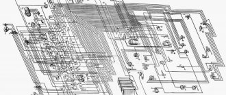
Electrical diagram of URAL-6370
- 1. Car tachograph
- 2. Engine Interface Unit (ECU)
- 3. Warning lamp block
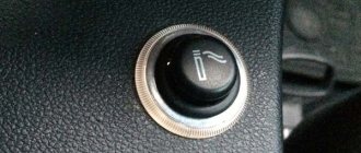
- 4. Cruise control switch
- 4. Cruise control switch
- 5. Starter and instrument switch
- 6. Steering column switch for turns and headlights
- 7. Steering column wiper and washer switch
- 8. Electronic speedometer
- 9. On-board voltage indicator
- 10. Electronic tachometer
- 11. Coolant temperature gauge
- 12. Oil pressure indicator in the engine lubrication system
- 13. Fuel level indicator
- 14. Two-pointer pressure gauge
- 15. Auxiliary brake switch
- 16. Center differential lock switch
- 17. Unloading area headlight switch
- 18. Rear fog light switch
- 19. Cross-axle differential lock switch
- 20. Outdoor lighting switch
- 21. Turn signal breaker relay
- 22. Remote ground switch
- 23. Hazard switch
- 24. Rear fog lights R13
- 25. Cabin lift switch
- 26. Pump motor
- 27. Radiator grille open sensor
- 28. Thermobimetallic fuse
- 29. Cabin lift relay
- 30. Cabin heater valve.
- 31. Cabin heater motor
- 32. Electrically controlled left rear view mirror
- 33. Left turn signal repeater
- 34.56. Cabin lights
- 35. Cabin lantern illuminating the loading area
- 36.57. Door lamp switches
- 37. Front left contour lamp
- 38. Left side marker light
- 39,40,41. Road train sign lights
- 42. Road train sign switch
- 43. Rear view mirror control unit
- 44. Pads for connection with independent heater and heater
- 45. Illumination of cabin heater control.
- 46. Cab heater tap control switch.
- 47. Cab heater motor control switch
- 48. Right side marker light
- 49. Front right contour lamp
- 50. Electrically controlled rear view mirror, right
- 51. EDC diagnostic switch
- 52. ODI diagnostic switch
- 53. Portable lamp socket
- 54. Diagnostic connector
- 55. Right turn signal repeater
- 58. Platform lift switch
- 59. Dump trailer control switch
- 60. Heated mirror switch
- 61. Accelerator pedal
- 62. Fuse block F1
- 63. Fuse block F2
- 64. Fuse block F3
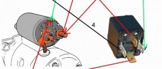
- 65. Starter relay R1
- 66. Relay for unloading terminal “15” R2
- 67. Relay for unloading terminal “15” R3
- 68. Wiper relay R4
- 69. Additional relay for rear fog lights
- 70. Side light relay R6
- 71. Fuse block F4
- 72. Low beam headlight relay R7
- 73. High beam headlight relay R8
- 74. Horn relay R9
- 75. Stop signal relay R10
- 76. Fuse block F5
- 77. Fuse block F6
- 78. Heated mirror relay for URAL cars
- 79. Headlight range control unit
- 80. Relay brake pedal position sensor
- 81. Center differential switch RK
- 82. Power take-off switch
- 83. Additional power take-off switch
- 84. Transfer case gear button
- 85. Transfer case gear selector
- 86. Center differential solenoid valve
- 87. Low gear solenoid valve RK
- 88. Neutral solenoid valve RK
- 89. High gear solenoid valve
- 90. Solenoid valve for power take-off
- 91. Additional power take-off solenoid valve
- 92. Windshield washer motor
- 93. Wiper motor
- 94.107. Additional high beam headlights
- 95.106. Fog lights
- 96. Left turn signal
- 97. Left low beam headlight module
- 98. Left headlight corrector motor
- 99. High beam headlight module with left side marker
- 100,101. Beep signal
- 102. High beam headlight module with right side marker
- 103. Right headlight corrector motor
- 104. Right low-beam headlight module
- 105. Right direction indicator
- 108,109,116,117. Side marker lights
- 110. Rear right lamp
- 111,112. Unloading area lights
- 113. Left rear lamp
- 114,115. Trailer sockets
- 118. Engine brake flap valve
- 119. Camshaft speed sensor
- 120. Pressure sensor URAL 6370
- 121. Low pressure and low temperature sensor top
- 122. Oil pressure and temperature sensor
- 123. Boost pressure and temperature sensor
- 124. Camshaft speed sensor
- 125. Fan control valve
- 126. Fan speed sensor
- 127. Ambient temperature sensor
- 128. Fuel measuring device
- 129,150,131,132,133,134. Fuel injection nozzles
- 135. Electronic control unit
- 136. Heating elements for air preheating
- 137. Air preheating relay
- 138,139. Heating elements for heating fuel fine filter
- 140. Fuel heating thermostat
- 141. Air dryer heating element
- 142. Water in fuel level sensor
- 143. Heating element for heating fuel in the coarse filter
- 144. Starter
- 145. Generator
- 146. Fuel level sensor
- 147,148. Rechargeable batteries
- 149. Ground switch
- 150,151. Wheel lock sensors
- 152. Sensor for turning on the center lock
- 153. Downshift sensor RK
- 154. Power take-off switch
- 155. Center lock sensor
- 156. Air filter clogging sensor
- 157,158. Pneumatic brake signal switches
- 159. Electro-pneumatic valve for lifting a dump trailer
- 160,161. Electro-pneumatic valve for platform lift
- 162,163,164. Emergency air pressure sensors
- 165. Parking brake sensor
- 166. Speed sensor
- 167. Neutral sensor
- 168. Clutch sensor
- 169. Reverse signal sensor
- 170. Electro-pneumatic valve for interaxle locking
- 171. Electro-pneumatic valve for inter-wheel locking
Modifications
Based on the dump truck, numerous modifications were created for various tasks. There are non-standard modifications, for example, armored army ones. Next, the most popular car modifications will be considered.
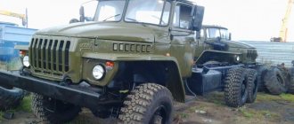
Car Ural 55571-40
Dump truck with rear unloading based on the original model. Used for transporting construction waste, sand, soil and other construction materials. The main difference from the original model is the load capacity increased by three tons.
Photo of the car Ural 55571-40
Main characteristics of the car
| Length, mm | 7735 |
| Width, mm | 2500 |
| Height, mm | 2980 |
| Load capacity, kg | 10000 |
| Maximum loaded weight, kg | 20775 |
| Engine Variation | YaMZ-236NE2 |
| Engine power, l. With. | 230 |
Fire truck
Modification of the original model, three-axle tanker AC 5.5 40. Used for fire fighting. It has characteristics that are almost identical to the base model in almost all respects. The dimensions have changed (now they are 8000 x 2500 x 3400). A fire installation has appeared that can accommodate six cubic meters of water. There is a foam block with a capacity of 360 liters. Pump capacity is 40 liters per second and higher.
Tank AC 5.5. 40 based on the Ural 5557 car
Dump truck
The car was originally a dump truck, but currently the 55571-44 modification with dimensions 8170x2500x3275 mm and a YaMZ-236NE2 engine is most often used as a dump truck. The model has a double all-metal cabin with a sleeping bag.
Photo of dump truck 55571-44
Farmer
For more convenient use in agriculture, the Ural 5557 is sometimes equipped with a hydraulic body lifting mechanism, which also allows unloading in two directions - this is most convenient for bulk cargo. Usually the Ural model 5557-8603043 mechanism is used. Models with this mechanism are called “agricultural machines” and one of the most popular is the Ural 5557-10 with a load capacity of 6745\16500 kg.
Ural 5557-10
In the video you can see the cabin of the Ural 5557 car
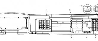
Relays and fuses
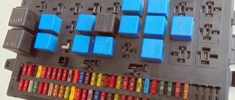
URAL relays and fuses are located in the cab on the mounting block to the right of the instrument panel under a removable cover. The serial number of fuses in the list corresponds to their numbering on the blocks.
1-relay for unloading terminal “15” (P2); 2-starter relay (P1); 3, 4, 6, 8, 9, 11 - fuse blocks; 5-relay for unloading terminal “15” (R3); 7-windshield wiper relay (R4); 10-rear fog lights relay; 12-diagnostic connector; 13-relay pneumatic brake signal switch (R12); 14-mirror heating relay (R11); 15-stop signal relay (R10); 16-horn relay (R9); 17-high beam relay (R8); 18-low beam relay (R7); 19-side light relay (R6); 20-relay additional rear fog lights (R5).
CAR ELECTRONICS REPAIR
General information
The electrical equipment system is single-wire, the negative pole of power sources and consumers is connected to the vehicle ground.
The sources of electricity are two batteries connected in series and a generator operating in conjunction with a voltage regulator. The connection of units and electrical equipment is carried out using wires with polyvinyl chloride insulation of various sections. The wires included in the bundles are made of a certain color to make them easier to find and easier to install. Single wires can be made in any color. The color of the wire can be indicated on the cuffs installed at both ends of the wire, the first letter of the color. The wires are connected to each other and connected to devices using plug connectors.
The car is equipped with a mechanically driven speedometer, electronic instruments and systems: tachometer, generator with a rectifier unit, etc. To avoid breakage of the flexible shaft of the GV300-05 speedometer, when installing and dismantling the instrument panel, lay the flexible shaft in such a way that the mark painted on shaft shell, was located outside the cabin directly behind the sealing sleeve of the flexible shaft passage hole, while the flexible shaft must be routed without forming a loop behind the instrument panel.
For reliable operation of these devices and systems, it is necessary to monitor the condition of the fuses installed in the blocks. Do not use non-standard fuses in the form of bent wire, bolts, washers, since in the event of a short circuit in the electrical circuit this will lead to immediate failure of electronics-based products. A blown fuse should be replaced with another one of the same intended operating current.