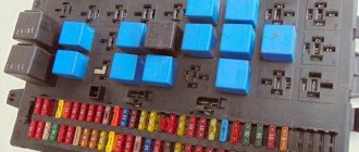
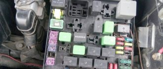
The purpose of fuses and relays may vary. Check the purpose with your documentation or diagrams on the back of the protective cover or inside the unit.
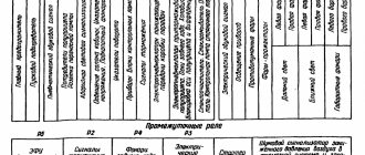
General layout of blocks
Description
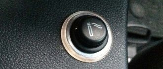
- Relay box behind switch panel
- Fuse box (F2, F3, F4, F6)
- Second relay block
- Fuse F1
- Starter relay
- Alarm relay
- Wiper relay
- Turn signal interrupter relay.
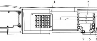
Fuse box
Photo diagram
General designation
row F2
| 1 | Reserve |
| 2 | Low beam right, corrector |
| 3 | Low beam left |
| 4 | Rear fog light |
| 5 | High beam right, high beam warning lamp |
| 6 | High beam left |
| 7 | Reserve |
| 8 | Right side marker, instrument lighting |
| 9 | Left clearance |
| 10 | Fog lights |
| 11 | Central light switch, spotlight |
| 12 | Lighthouses |
| 13 | Sleeping place, engine compartment lamp, road train lights |
row F3
| 1 | Wheel lock, radio |
| 2 | Gas leak alarm (on gas vehicles) |
| 3 | Power take-off, daytime running lights, winch |
| 4 | Electromagnetic engine cooling clutch, reversing lights |
| 5 | Ground switch relay coil |
| 6 | Buzzer (sound signal), brake signal relay coil |
| 7 | Generator excitation winding, tire inflation |
| 8 | Courtesy lamps, glove compartment lighting, instrument cluster power supply |
| 9 | Pendant lamp socket, heater motors |
| 10 | Horns, "+" trailer sockets, brake lights |
| 11 | Driver blower fan |
| 12 | Reserve |
| 13 | Heated mirrors, heated seats |
row F4
| 1 | Reserve |
| 2 | Electronic speedometer, electronic tachometer |
| 3 | Tractor ABS |
| 4 | Trailer ABS |
| 5 | Instruments, electronic speedometer, electronic tachometer |
| 6 | Tractor ABS, engine brake relay (valve) |
| 7 | Trailer ABS |
| 8 | Gas level sensor (on gas vehicles) |
| 9 | Wiper power supply |
| 10 | Engine control unit power supply |
| 11 | Electric flare device |
| 12 | Reserve |
| 13 | Reserve |
series F6 (for KAMAZ engines)
| 1 | The engine control unit |
| 2 | The engine control unit |
| 3 | Diagnostic connector |
| Brake relay | |
| 4 | Warning lamps |
| 5 | Warning lamps |
| 6 | Air suspension control unit |
| 7 | Urea pump |
| 8 | Urea pump |
| NOx sensor | |
| 9 | Reserve |
| 10 | Reserve |
| 11 | Automatic transmission control unit |
| 12 | Retarder braking signal |
| 13 | Automatic transmission control unit |
row F6 (for CUMMINS engines)
| 1 | The engine control unit |
| 2 | The engine control unit |
| 3 | Diagnostic connector |
| 4 | Reserve |
| 5 | Air suspension control unit |
| 6 | Air suspension control unit |
| 7 | Dosing pump |
| 8 | Urea heating line relay |
| Dosing pump | |
| 9 | Reserve |
| 10 | NOx sensor |
| 11 | Automatic transmission control unit |
| 12 | Automatic transmission, retarder brake signal |
| 13 | Automatic transmission control unit |
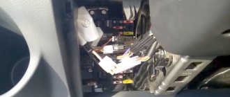
Relay behind switch panel
Relay behind the switch panel for vehicles with engines of environmental class 5 1 - ECU relay (for certain configurations); 2 — ECU relay (for individual configurations); 3 — braking relay; 4 — fuel heating relay; 5 — relay for switching on instruments and starter; 6 — battery switch relay; 7 - power control relay after locking the instrument switch and starter; 8 - 12 V socket relay; 9 — windshield wiper stop relay; 10 - radio disconnect relay
Relay behind the switch panel for vehicles with engines of environmental class 6 1 - Clutch relay; 2 — starter blocking relay; 3 — pump power relay; 4 — relay for the heated line to the nozzle; 5 — relay for the heated line from the pump to the tank; 6 — fuel heating relay; 7 — relay for switching on instruments and starter; 8 — battery switch relay; 9 — power control relay after locking the instrument switch and starter; 10 - 12 V socket relay; 11 – relay for the heated line from the tank to the pump; 12 — radio disconnect relay; 13 — windshield wiper stop relay; 14 - heater relay
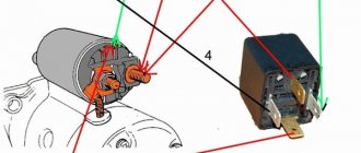
ElectroSanya › Blog › Starter via relay and its blocking
I installed two relays for the starter, one powers the starter from the battery, to put it bluntly. There is no big difference in this, but the contacts on the ignition switch will no longer burn, if anyone has this problem! And I set the second relay to inhibit the starter when the engine is running, a very good thing, especially for training girls in the car, who, instead of turning off the car, turn on the starter. The principle of operation of the circuit is simple: when we turn on the starter, the circuit is closed, the starter turns, the engine starts, the generator supplies a minus signal to the “charge control lamp relay”, as well as to the starter blocking relay
Comments 20
Something's not working
What and what kind of generator? Perhaps it’s not a minus coming from the generator, but a plus! Another option, as I did now, is to connect the battery to the charge lamp
When the generator is excited, it goes +
then pin 86 of the second relay is not to +12 but to ground
In the diagram, 30 and 87 are closed.
yes it is on the diagram
good topic, I want to install 1 relay for myself)))
one thing is good, but there were cases when the engine cannot be heard at idle or a girl is driving and accidentally continues to hold the starter after starting, so the blocking is a cool thing
Probably not, but where should it hang?
What amperage should the relay have? or which specific ones need to be found by marking?
for the starter relay, preferably 30A; for blocking, the 702 charging relay is best, it is suitable
Thanks for the blog. Healthy.
What amperage should the relay have? or which specific ones need to be found by marking?
Gray, why don’t you have a relay for the starter))
Great. I've been wanting to do this for a long time. Now draw a diagram to use only one relay - Starter blocking.
Well, you take the lower relay closed and that’s it! relay 702 from charging is suitable, or 5-pin but instead of 87 use 88
Light signaling model 431185
In order to safely use the car and indicate the maneuvers being performed, the manufacturer equipped the model with a light signaling system. Light alarms include:
- Direction indicators;
- Alarm;
- Car brake lights;
- Lamp for reversing vehicle;
- Road train lights.
The blinking of the direction indicator lamps is carried out due to the operation of the breaker relay. The turn signal and hazard warning relays are housed in one housing.
Turning on the direction indicators is carried out using a combination switch located on the steering column of the car. A separate switch is provided to turn on the hazard warning lights.
The brake lights are switched on using a pneumatically driven switch. When you press the brake pedal, compressed air pressure acts on the switch membrane. The membrane closes the contacts for turning on the brake lights.
IMPORTANT: Thanks to the pneumatic drive of the switch, the brake lights come on both in the service brake system mode and when the parking brake is applied.
Trailer lights are used to identify a vehicle and trailer on public roads. The lights are turned on by a switch located on the front panel of the car. You can also read about KamAZ 55111.
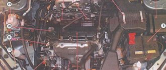
Features of electrical equipment
Now let's move on to the description of the KAMAZ electrical circuit.
All models of KAMAZ 6520, 55102 and other trucks are equipped with the following subsystems:
- Starting the power unit.
- Turning lights and hazard warning lights.
- Heating unit, power supply system, windshield cleaning mechanism.
- Vehicle interior lighting.
- Head lighting. It includes low and high beam headlights, fog lights if they are installed on the car, brake lights, and dimensions.
- Tidy. This node is considered one of the main ones in the on-board network, since it contains the main sensors, devices and instruments, including a tachometer, speedometer, fuel level sensor, etc. In addition, the control panel has light indicators that turn on when the lighting is activated , handbrake, etc. Thanks to the indicators, the driver can indirectly determine the status of some components.
- Vehicle anti-theft system, if installed.
- Fuse block. This component protects the car's electrical circuits from possible voltage surges. It contains fuses responsible for the operation of the main electrical equipment.
- A control unit, thanks to which the normal operation of the main units and equipment of the car is guaranteed.
- Audio system, if the car is equipped with one.
In order for the KAMAZ electrical circuit to operate in normal mode, the condition of the wiring must be at least satisfactory.
In addition, the operation of the electrical circuit is possible if:
Video “The process of repairing the lighting and electrical circuit of a KAMAZ vehicle”
Attention: The electronic auto parts catalog is intended for reference purposes! Our company only sells those products that have prices listed.
| Number | 1/38358/71 |
| Name | Bolt M6-6gx10 |
| Quantity per "6520" | 12 |
| Fastener | Yes |
| Material | other metal materials, i.e. not steel, not brass, not light alloy, not copper |
| Coating | galvanizing |
Part number on drawing:
Bolt M6-6gx10
Serial number: 1/38358/71 Quantity per model: 12
In warehouses: 19 pcs.
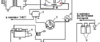
Engine starting
The KamAZ car engine is started by an electric starter. The electrical circuit of KamAZ 43118 assumes remote control of the starter. This is done by turning the key in the ignition switch located on the front panel of the car.
The electric starter supply voltage is 24 volts. The starter is equipped with a retractor relay necessary to engage the drive gear with the engine flywheel and turn on the starter motor. After starting the power plant, the retractor relay rod returns in the opposite direction using a power spring.
Glass cleaning and auxiliary heater
The windshield is cleaned by brushes driven by an electric motor.
It has two rotor speeds. The wiper motor is controlled by a combination switch. The windshield wiper system includes an electric washer motor.
To maintain the required temperature in the cabin, KamAZ 431185 is equipped with an autonomous heater. Air circulation through the heating radiator is carried out using an electric fan.
From the above it follows that the KamAZ 43118 color wiring diagram is necessary for performing maintenance and repair of electrical equipment. The machine's wiring consists of several subsystems. The wiring is protected by fuses.
KamAZ 43118 - technical characteristics
KamAZ-43118 is an all-wheel drive truck with a 6 × 6 wheel arrangement. This vehicle, with its high cross-country ability, has become simply irreplaceable in hard-to-reach areas of Russia. Also, having a lifting capacity of 10 tons, the machine became the basis for a large number of various special equipment and, above all, truck cranes.
KamAZ-43118 has the following overall dimensions (in millimeters):
- Length – 8580;
- Width – 2500;
- Height – 3455;
- Ground clearance – 385;
- Wheelbase – 3960+1320.
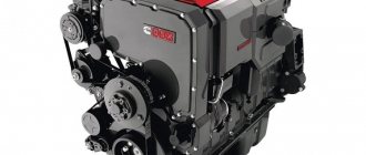
The vehicle is equipped with a KamAZ-740.30-260 diesel engine that meets Euro-2 environmental standards. This power unit is made according to the V8 formula. It has a displacement of 10.85 liters, is equipped with a turbocharger and develops a power of 260 hp. With.
This power unit allows the car to reach a maximum speed of 90 km/h.
The empty weight of the truck is 10,400 kg. The weight of a fully loaded vehicle can be 20,700 kg.
ROSTAR
- V-shaped rods
- Jet rods
- Jet rod repair kits
- Suspension shock absorbers
- Silent blocks
- Steering rods
- Stabilizer links
- Steering rod ends
- Drum brake pads
- Disc brake pads
- Ladder springs
- Towbar pins
- Transmission control drive parts
- Brake chambers, energy accumulators
- Pneumatic hydraulic boosters (PGU)
- Caliper repair kits
- Parts made of polymer composite materials
- Suspension brackets
- Pneumatic springs
- Brake levers
In warehouses: 107 pcs.
In warehouses: 398 pcs.
| Number | 738.3747-20 |
| Name | Relay |
| Quantity per "6520" | 2 |
Part number on drawing:
Relay
Serial number: 738.3747-20 Quantity per model: 2
In warehouses: 370 pcs.
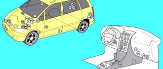
How to determine the malfunction?
There are several options for diagnosing the health of a car's electrical circuit, which can be done at home. For example, you can check the presence of voltage in a certain area; for this you can use a multimeter or a test light.
So, if the circuit is faulty, the procedure is as follows:
- First, you need to connect one of the probes of the tester or warning lamp to the “-” terminal of the battery; it can also be connected to the truck body.
- The second probe must be connected to the connection of the area being diagnosed, and it is desirable that it be installed as close as possible to either the battery or the fuse.
- If, as a result of the connection, the control light starts to light up or voltage appears on the multimeter display, this means that this section of the circuit is working normally. That is, all elements are connected as needed, and no wiring repairs are required. But it must be taken into account that in some circuits voltage may be present if the ignition key is turned to a certain position.
- Next, the remaining sections of the circuit are diagnosed, the procedure is carried out in a similar way.
- If you find a point where there is no voltage, then most likely the cause of the problem lies between this point and the last area where there is voltage.
- It should be noted that in most cases, problems with wiring are caused by poor contact.
You can also try to find a short circuit in the system at home:
RELCOM
In warehouses: 213 pcs.
In warehouses: 235 pcs.
In warehouses: 27 pcs.
| Number | 733.3747-10 |
| Name | Alarm relay |
| Quantity per "6520" | 1 |
Part number on drawing:
Alarm relay
Serial number: 733.3747-10 Quantity per model: 1
In warehouses: 69 pcs.
In warehouses: 155 pcs.
In warehouses: 7 pcs.
| Number | 901.3747 |
| Name | Relay assembly |
| Quantity per "6520" | 11 |
Part number on drawing:
Relay assembly
Serial number: 901.3747 Quantity per model: 11
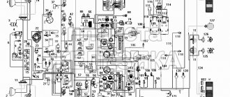
KamAZ 431185 euro 5: Electrical circuit diagram
Collection of electrical circuits for the Kamaz truck.
Electrical equipment of cars consists of the following systems: power supply, light signaling, external and internal lighting, instrumentation; heating systems, windshield cleaning and sound alarm systems, engine starting. Below are the electrical diagrams of these systems and their descriptions. There are two options - for various modifications of the Kamaz vehicle. General electrical circuit of KAMAZ models 5320, 5410, 5511
Electrical diagram of KAMAZ light signaling systems
Electrical diagram of KAMAZ power supply and cleaning systems
Electrical circuit of external and internal lighting of KAMAZ
The second option, where the circuits are divided into nodes
Power supply diagram for all Kamaz vehicles with an 800W generator
Power supply diagram for KamAZ vehicles with a 2kW generator
Kamaz engine starting diagram
Electrical circuit of instrumentation
Windshield wiper, heating and sound alarm circuit
Kamaz interior lighting diagram
Electrical circuit of external lighting
Diagram of external light signaling and wheel locking