Transfer case of the Ural-4320 car
Military Encyclopedia - historical and archival military-patriotic portal
home☆Soviet military encyclopedia☆military equipment☆military science☆military review☆history of weapons☆forum
military equipment ☆ articles on the VAT device ☆
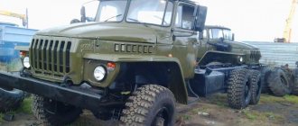
The URAL-4320 vehicle is equipped with a two-stage transfer case with an asymmetrical cylindrical center differential lock and a mechanical drive. Transfer case ratios in first gear are 2...15, in second gear - 1.3. The box is attached to the car frame on four rubber pads. The general structure of the transfer case (Fig. 112) of this vehicle is the same as that of the KamAZ-4310 vehicle.
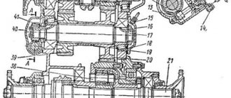
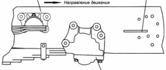
Rice. 112. Transfer case of the URAL-4320 car : 1, 22, 37 - flanges; 2, 10, 16, 25, 33, 40 — bearing caps; 3, 18 — tapered roller bearings; 4, 39 — top gears; 5 - bushing; 6 — top hatch cover; 7 — gear clutch; 8, 20 — low gears; 9 — transfer case housing; 11 — primary shaft; 12 — speedometer drive gear; 13 — driven gear of the speedometer drive; 14 — speedometer sensor flange; 15 — fitting of the sealing system; 17 — intermediate shaft; 19 — spacer sleeve; 21 — rear axle drive shaft; 23 — oil removal ring; 24 — bearing nut; 26 — rear differential bearing housing; 27 — rear differential race; 28 — lower shaft gear; 29 — crown gear; 30 — sun gear; 31 — front differential race; 32 — differential lock clutch; 34 - bolt; 35 — flange reflector; 36 — front axle drive shaft; 38 — satellite; 41 — bearing nut
The crankcase is cast iron, one-piece, and has a hatch on top that is closed by a lid with an oil guide tray.
Oil is poured into the crankcase through the top hatch with the cover removed or through the hole under the control plug located on the rear wall of the crankcase. The oil is drained through the lower hole, closed with a plug with a magnet. Crankcase ventilation is carried out through a fitting, the tube of which is included in the general sealing system of the units.
The drive shaft rotates on two tapered bearings installed in the crankcase and covered with covers. Metal shims are placed under the front bearing cover, and an oil seal is installed in the cover. Power can be taken from the rear toothed end of the shaft when an additional power take-off box is installed on the vehicle to drive the winch. The gears of the second and first gears are mounted on bronze bushings. Between the gears on the shaft splines there is a gear shift coupling. To supply oil to the gear bushings and their teeth, there are holes on the shaft and gears.
The intermediate shaft also rotates on two tapered bearings closed with blind caps; Metal gaskets are placed under the back cover. The gears are mounted on the shaft with splines. At the front end of the shaft, the speedometer drive gear is mounted on a key; the driven gear is located in the boss of the bearing cap. The driven gear drives the speedometer sensor.
The center differential consists of: a carrier with a drive gear, a sun gear, an epicyclic gear, and four satellites. The carrier is composite; it includes front and rear races connected to the drive gear; in addition, a support washer is attached to the front race.
The front axle drive shaft and the rear bogie drive shaft rotate on ball bearings and are supported by the differential. These shafts are sealed with rubber seals; There are oil rings between the bearings and seals on the shafts. A differential lock clutch is installed on the splines of the front axle drive shaft.
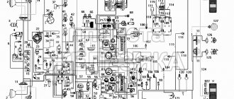
Rice. 113. Control of the transfer case of the URAL-4320 car : 1 - differential lock lever; 2 — gear shift lever; 3 - preload spring; 4 - roller; 5 — bracket and engine mounts; 6, 7 — thrust; 8, 9 - leashes; 10 — bracket for leashes; 11 — gear shift fork rod; 12 — differential lock fork rod; 1 - differential unlocked; I - differential locked; P-front position (second gear engaged); N - middle position, neutral, 3 - rear position (first gear engaged).
The transfer case control drive is mechanical (Fig. 113). It consists of two levers 1 and 2, two rods 6 and 7 with forks, two leads 8 and 9 with bracket 10, two rods 11 and 12 with forks and two clamps. Differential lock lever 1 and gear shift lever 2 are installed in bracket 5 on a common shaft 4. Bracket 5 is also the upper right bracket of the rear engine mount.
Transfer case operation. When engaging first gear, the driver, using lever 2 and drive parts, moves clutch 4 (see Fig. 112) back and connects gear 5 to the drive shaft.
The torque is transmitted through gears 5 and 13 to the drive gear 24 of the differential, in which it is distributed between shafts 28 and 14 in a ratio of 1:2.
In second gear, clutch 4 connects the drive shaft to gear 1. Torque is transmitted through gears 1.32 to the intermediate shaft and through gears 13 and 27 to the differential.
It is necessary to switch the transfer case from second to first gear only after the car has come to a complete stop.
The differential is locked using lever 1 (see Fig. 113), while the sun gear 27 (see Fig. 112) is connected to the front carrier race through shaft 30 and coupling 29.
Transfer case adjustments. The tapered bearings of the drive and intermediate shafts are adjusted by changing the number of shims under their caps. The axial movement of the drive shaft should be 0.15-0.20 mm, the intermediate shaft - 0.08-0.13 mm. The bearings are adjusted with the transfer case removed from the vehicle. Axial movements of the shafts are checked by an indicator.
In the neutral position, coupling 4 should be placed on the splines of shaft 8 so that the difference in the lengths of the drive shaft splines on both sides of the coupling does not exceed 1 mm. The position of the coupling is adjusted by turning the rod 20.
Clutch 29 in the extreme forward position (with the differential unlocked) should not touch the ends of the front cage 26. The position of clutch 29 is adjusted by turning rod 18.
The transfer case control drive is regulated by changing the lengths of rods 6 and 7 (see Fig. 113). With the middle position of the rod 11, corresponding to the neutral position of the gear shift clutch, lever 2 should be in the middle of the slot in the cab. When the rod 12 is in the forward position, lever 1 must also be in the forward position.
The transfer case is lubricated by splashing. The box crankcase is filled with 3.5 liters of TSp-15k oil.
When installing the auxiliary power take-off box on the winch, if it is turned on, the drive shaft gear bushings are lubricated under pressure with oil supplied from the transfer case housing by a plunger pump installed in the auxiliary power take-off box.
Tags: car transmission ☆ Ural 4320 ☆ car device ☆
| Transfer case of KamAZ-4310 < Prev. | Track. > Transfer case of the ZIL-131 car |
We take out garbage from the apartment
Garbage removal in Moscow and the Moscow region
- Contacts:
- +
- around the clock
- Moscow
© Military Encyclopedia. Map of site.
Development history
The need to create a new vehicle based on the Ural-375 three-axle all-wheel drive truck arose soon after the start of production of this model in 1960. The main drawback of all the first modifications of this car was the extremely voracious gasoline engine, which consumed about 50 liters of expensive high-octane A-93 gasoline per 100 kilometers.
At the same time, the design of the car itself was considered quite reliable and efficient. The essence of the upcoming modernization was to replace the gasoline engine with a diesel unit, which consumes simpler fuel and, if possible, is economical. Engineers at the Ural Automobile Plant began independently developing such an engine, but in the end, at the level of industry management, it was decided to transfer this process to the Yaroslavl Motor Plant (YaMZ).
In 1969, YaMZ specialists introduced a new diesel engine in combination with a gearbox for a car based on the then main Ural-375D model. But the first versions of the new vehicle did not show the performance characteristics (tactical and technical characteristics) required primarily by military customers, and after a series of tests that lasted for several years, serial production of the Ural-4320 model began in 1977, and based on the KamAZ engine that had appeared by that time -740.
However, during the preparation of the new model for production, the specialists of the Ural Automobile Plant were able to achieve a high degree of unification of vehicles of the Ural-4320 family with the units and structural elements produced at home. At the same time, any serious modifications to the design of the machine turned out to be minimal.
Purpose
Attachments (generators, winches, pumps) installed on vehicles are in many cases equipped with their own drive motors, which are powered by an on-board generator or batteries. But the practice of using special equipment has shown that a more effective solution will be one that allows you to directly use the power of a running internal combustion engine. This method can significantly reduce energy consumption and reduce the cost of the cars themselves by simplifying the design.
It is to ensure the operation of the attachments that the power take-off is used. It transmits part of the torque of the internal combustion engine to the actuators. Note that fuel consumption in this case practically does not increase.
Stages of adjusting the transfer case differential lock clutch
- The position of the clutch should be checked and, if necessary, adjusted.
- To adjust the position of the clutch, it is worth locking the differential by turning the rod.
- When checking the position of the coupling, you should install the rod, fixing it in the forward position by the flange, turning the shaft related to the front axle drive.
- The correct position of the coupling is when it touches the splined end. If this is not the case, you should move it forward while rotating the rod clockwise.
- To adjust the position of the seventh clutch, it is worth adjusting the selection of the thickness of the gaskets. The coupling is secured normally when the difference between the splines on both sides of the carriage is no more than one millimeter.
User manual
Regulatory documentation relating to the operation, maintenance (MOT) and repair of Ural 4320 model trucks notes the versatility of this vehicle (transporting people, cargo and towing trailers), as well as its ability to operate on all types of roads in any terrain. The range of ambient temperatures for which the vehicles were designed was quite wide and ranged from plus 50 to minus 50 degrees Celsius.
In addition, the operational requirements reflected the very high reliability parameters of the Miass truck. If the initial maintenance for a new car usually required 1000 km of run or 50 engine hours, then subsequent maintenance was carried out after 4 thousand km or 125 hours of engine operation, and a more in-depth one - at four times higher rates. Moreover, most maintenance items boiled down to tightening nuts, cleaning, etc. operations.
How to check functionality
To check the functionality of the device, you must perform the following operations:
- The car is parked and secured using the hand brake.
- Turns off, then disconnects the working attachment.
- If the PTO is equipped with a pump, remove the plug from it.
- They start the car engine, activate the PTO, and engage the gear.
- Check the serviceability of the power take-off and the functionality of the pump.
Please note that the driver must carry out the inspection only with a partner in order to ensure safe working conditions.
Control system
In the Urals, PTO control using a pneumatic system was used. This solution allows the driver-operator to start the box and control the operation of the equipment without leaving the cab, which is important in bad weather conditions.
To start, it is enough to turn the crane lever, which acts on the rod, which turns on the pneumatics. The start of the attachment occurs after the driven and driving gears are engaged, which ensure the transmission of torque.
Operating principle and troubleshooting of the Ural gearbox
The Ural gearbox is a device in the vehicle system that is responsible for transmitting power.
How does the checkpoint work?
The KPP-141 device, installed on some Ural models, includes the following elements:
- Coupling mechanism. It helps temporarily separate the engine and transmission. This allows you to change gears without reducing the speed of the power unit.
- Driven gears and shafts. The drive, intermediate and secondary shafts are installed here.
- Synchronizer. It ensures silent operation of the mechanism and equalization of gear speeds.
The gears rotate freely when the neutral mode is engaged, at which time all clutches and synchronizers are in the open position.
When the driver begins to squeeze the clutch mechanism and shifts the handle to some other gear, a special fork device begins to move the clutch into the engagement position with the corresponding pair at the end of the gear.
The gear mechanism is rigidly fixed to the shaft and stops spinning on it. The clutch in this position facilitates the transmission of rotational motion and traction force.
While the vehicle is moving, the gearbox is activated by the gear shift knob. It moves sliders equipped with forks, which begin to move the synchronizers at the required speed. A color diagram of gear shifting is in the Ural user manual.
Gear ratios of the Ural box:
- first stage - 5.26;
- second stage - 2.90;
- third stage - 1.52;
- fourth stage - 1.00;
- fifth stage - 0.664;
- reverse gear - 5.48.
Malfunctions and repairs
Basic malfunctions and repairs of the box:
- Extraneous noise in the mechanism. In this case, it is recommended to conduct an external inspection of the system and replace damaged and worn parts.
- The shafts move along the axis. It is necessary to replace the parts that secure the bearing, or replace failed bearings.
- Unstable operation of the gearbox. This problem may be due to wear on the reverse spline shaft bushings. Damaged mechanisms should be replaced.
- The clutch does not engage fully. In this case, it is recommended to conduct an external inspection of the coupling mechanism for damage and defects, check the level of lubricating fluid in the system and replace damaged elements.
- The fork rods are difficult to move. This malfunction can be caused by damage to the locking pins and synchronizers. It is necessary to replace the mechanisms with new ones.
- If the gearbox switches off spontaneously, it is necessary to adjust the gap between the valves, replace worn synchronizer rings, install new springs, and tighten fasteners.
- If the switching is unclear, you need to remove the cover of the locking device and inspect the main components for wear, replace the clutch and gears.