5.3.3 Brake systems of Ural vehicles
5.3.3 Brake systems of Ural vehicles
The service braking system must ensure a reduction in speed and stopping the vehicle, regardless of its speed, load and slopes of the roads for which it is intended.
The drive of the brake mechanisms is mixed (pneumohydraulic), dual-circuit, with separate braking of the wheels of the front and two rear axles. The control is carried out by a pedal in the driver's cabin, connected by levers and rods to a two-section brake valve.
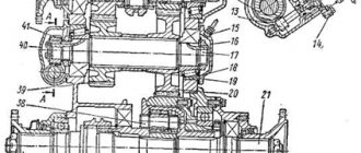
The working brake mechanism is drum type with internal pads 5 (Figure 5.45), interchangeable for all wheels. Each brake mechanism has two hydraulic cylinders 1, made in one housing. The brake pads are installed on support axles 7. The working brake mechanism is adjusted as the linings wear out by reducing the gap between the lining and the drum using eccentrics 3.
Figure 5.45 – Service brake mechanism
1 – wheel cylinder; 2 – brake shield; 3 – adjusting eccentric; 4 – key; 5 – brake pad; 6– friction lining; 7 – brake pad axis; I – gap reduction; II – increasing the gap
Figure 5.46 shows a diagram of a pneumohydraulic brake drive. It consists of two main parts - pneumatic and hydraulic.
The pneumatic part of the drive includes a brake valve 4 and two pneumatic boosters 8, which are connected by a pipeline to the lower section of the brake valve 4. The upper section of the brake valve is connected through pipeline 12 to the pneumatic equipment of the trailer. The hydraulic part of the drive is double-circuit. The main brake cylinder is connected to the first pneumatic booster 8 and actuates the brake mechanisms of the wheels of the front and middle axles of the vehicle. The main brake cylinder is connected to the second pneumatic booster 8 and operates the brake mechanisms of the rear axle wheels of the vehicle. When you press the brake pedal, compressed air from the brake valve 4 through the pipeline enters the pneumatic amplifiers 8, which activate the brake cylinders of the hydraulic drive circuits. The fluid displaced from the main brake cylinders operates the brake mechanisms of the car's wheels. In this case, the fluid pressure in the wheel brake cylinders is proportional to the air pressure in the pneumatic boosters 8. The hydraulic part of the drive ensures simultaneous braking of all wheels of the vehicle. The pneumatic part of the drive makes it easier to control and allows you to brake the towed trailer.
Figure 5.46 – Diagram of the pneumohydraulic brake drive of the Ural car
1 – compressor; 2 – air analysis unit; 3 – air bleed valve; 4 – brake valve; 5 – intercylinder reducer; 6 – air cylinder; 7 – safety valve; 8 – pneumatic amplifiers; 9 – hand brake lever; 10 – fitting of the wheel hydraulic cylinder; 11 – towing valve; 12 – pipeline to the trailer brake equipment
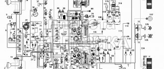
The drive provides the ability to connect the brake systems of trailed vehicles with single-line or two-line brake actuators. The schematic diagram of the brake drive is shown in Figure 5.47.
Compressor 29 supplies compressed air through pressure regulator 4 to the safety valve block. The unit consists of triple 5 and single 7 safety valves that distribute and fill air cylinders into 3, 9 and 27 independent circuits:
– front wheel brake drive;
– drive the brake mechanisms of the middle and rear wheels;
– combined drive of the brake mechanisms of trailer wheels.
Figure 5.47 – Diagram of the drive of service brakes and the combined drive of trailer brakes
1 – two-pointer pressure gauge; 2 – towing valve; 3, 9, 27 – air cylinders; 4 – pressure regulator; 5 – triple protective valve; 6 – pneumatic trailer brake release valve; 7 – single protective valve; 8 – pressure drop sensors; 10 – trailer parking brake control valve; 11 – pneumatic fuel shut-off cylinder; 12 – pneumatic cylinder for closing the exhaust flap; 13 – double-line valve; 14 – safety valve; 15 – trailer brake control valve with a two-wire drive; 16 – control head (yellow) automatic connecting; 17 – feeding head (red) automatic connecting; 18 – connecting head type A; 19 – trailer brake control valve with single-wire drive; 20 – brake force regulator; 21 – brake signal activation sensors; 22 – brake fault indicator sensors; 23 – wheel cylinders; 24 – pneumatic brake booster; 25 – control valves; 26 – condensate drain valves; 28 – brake valve; 29 – compressor
The first main circuit consists of an air cylinder 3, the upper section of the brake valve 28, a pneumatic booster 24 and wheel cylinders 23, and the second main circuit consists of an air cylinder 27, the lower section of the brake valve 28, a brake force regulator 20, a pneumatic booster 24, wheel cylinders 23.
The third circuit consists of an air cylinder 9, trailer brake control valves: 19 - with a single-wire drive and 15 - with a two-wire drive, a type A connection head 18 for connecting trailers with a single-wire drive, automatic connection heads 16, 17 for connecting trailers with a two-wire brake drive .
Air is taken from air cylinders 3, 27 through a triple safety valve 5 to activate the electrical signal sensor and other consumers.
If it is necessary to control the air pressure, control outlet valves 25 are installed in each circuit, to which a portable pressure gauge can be connected.
When driving a car with a trailer that has a single-wire brake drive, the connection of the car with the trailer is carried out by connecting head 18, two-wire – by connecting heads 16, 17.
When you press the brake pedal, the first and second circuits of the vehicle's brake drive are activated, as well as the third circuit of the trailer's brake drive.
If one of the circuits fails, the others remain operational.
To brake a car with a trailer in a parking lot, the parking brake lever is set to the upper fixed position, while control valve 10 releases compressed air from output II of the control valve, valve 15 (Figure 5.47) and actuates the brake mechanisms of the trailer.
Minimum air pressure sensors are installed in the air cylinders. The pneumatic boosters are equipped with sensors that indicate a malfunction of the service brake system (brake fluid leakage or large gaps between the pads and the drum).
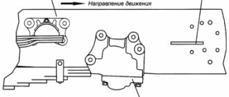
Pneumatic brake boosters with master brake cylinders are installed under the cabin: the first is on the left side member, the second is on the fuel tank bracket. When you press the brake pedal, the valve in the brake valve opens, and air flows through the pipeline under the pistons 8 and 12 (Figure 5.48) of the pneumatic booster.
Under air pressure, the rod and pistons are mixed and, through a pusher, acts on the piston 16 of the main brake cylinder, which displaces fluid into the brake line.
When the brakes are released, the air from the pneumatic booster escapes into the atmosphere through the brake valve. The pistons of the master brake cylinder and pneumatic booster return to their original position under the action of springs.
Figure 5.48 – Pneumatic booster with master brake cylinder
1 – bypass valve; 2 – reservoir for brake fluid; 3, 5 – pneumatic cylinders; 4 – spacer; 6 – rod; 7, 10, 11, 13, 17 – cuffs; 8, 12, 16 – pistons; 9 – screed; 14 – brake fault indicator switch; 15 – main brake cylinder; 18 – check valve; a – radial hole; b – from the brake valve; c – to the brake system
Pneumatic brake drive devices are used to create a supply of compressed air on the vehicle and to operate the brakes of the vehicle and trailer. The purpose and design of devices is considered in the brake system of KamAZ vehicles.
Adjusting the pneumatic-hydraulic drive
Ural service brake drive diagram
The pneumatic hydraulic drive of the Urals does not require adjustment and does not require maintenance.
The tightness of a separate pneumatic system is checked by a sharp decrease in pressure on a pressure gauge with two arrows (not lower than 700 kPa), which is located among the driver’s control instruments in the cabin. After stopping the engine (the brake pedal is not pressed), the pressure gauge needles should not twitch much or move noticeably. The same should be observed when the brake pedal is pressed for 20 seconds. At the same time, the tightness of the hydraulic part is assessed.
The functionality of the entire drive is checked by assessing the pressure (650–800 kPa) in all three circuits on pressure gauges connected to the control valves.
Malfunctions
Malfunctions of the brake system of the Ural-4320 and similar vehicles:
- slow increase in pressure in receivers due to damage to housings or lines;
- insufficient filling of the circuit cylinders, the cause is breakdown of the control valves or dirt in the lines;
- low pressure in air tanks installed on trailed equipment, the defect is associated with cracks in the parts;
- increased pressure in the receivers, the cause of the breakdown is a failure of the pressure regulator or a malfunction of the control pressure gauge;
- failure of the compression brake indicates problems with the pneumatic valves or a broken valve;
- the ingress of engine oil into the cavities of the pneumatic system indicates wear of the compressor piston group.
If a malfunction occurs in the brake system of a Ural vehicle, further operation is strictly prohibited. The damage must be repaired on site or the vehicle must be towed to the repair area using a rigid hitch.
How to bleed and adjust
To make the adjustment you must:
- Turn the eccentrics all the way, with the right part rotating clockwise and the left part counterclockwise. Adjustment of the gap using the pad axis is carried out only in case of wear of the braking surface.
- Loosen the position of the regulators by 30°.
- Check the temperature of the drums while moving. If overheating or insufficient deceleration occurs, readjust the components.
Before bleeding the brake lines, it is necessary to bring the air pressure in the receivers to normal. The surfaces of the cylinders and tanks should be thoroughly wiped from dirt.
To remove air locks from the main and wheel cylinders you need:
- Remove the protective cover installed on the bypass valve fitting. After this, the hose included in the factory tool kit is put on the tube.
- Prepare a clean glass or plastic container that can hold at least 0.3 liters of liquid. Fill the container 1/2 full with brake fluid and lower the free end of the hose into it.
- Unscrew the valve fitting 0.5-0.75 turns, then vigorously press the brake pedal several times, releasing smoothly.
- Manipulations continue until the release of gas bubbles from the tube stops. At the same time, clean liquid is added to the supply tank.
- Depress the brake pedal one last time and hold it in this position. Screw in the fitting and replace the cap.
- By analogy, bleed the wheel cylinders according to the scheme - middle (left), then rear left and right. Then the right middle wheel assembly, right and left front wheels are pumped.
- After removing air from all lines, adjust the fluid level in the supply tank and close the lid.
If fluid replacement is required, the cylinders are disassembled. A lubricant is applied to the working mirror to prevent corrosion.