Diesel power supply system D-245E3
The diesel power system, in accordance with the diesel engine configuration, consists of:
- a Common RAIL accumulator injection system, including a fuel pump,
booster gearbox of the injection pump drive, injectors, high-pressure fuel accumulator, speed sensors (crankshaft and input shaft of the injection pump drive gearbox), sensors for the state of the working environment (pressure and temperature of fuel and air), electromagnetic actuators (fuel pressure regulator, solenoid valves injectors), electronic control unit;
low pressure fuel lines;
high pressure fuel lines; intake manifold; exhaust manifold;
fine fuel filter; fuel pre-filter (coarse), air cleaner, fuel tank, charge air cooler, muffler.
The diagram of the diesel power system indicates a means of facilitating diesel starting at low ambient temperatures - a glow plug.
The diagram of the diesel power system is shown in Figure 1.
The monitoring and control circuit diagram of the COMMON RAIL power system is shown in Figure 2.
Location of sensors and actuators in Figure 2 and in the table.
Power to the electronic control, control and communication circuit unit must be supplied directly from the battery terminals.
The crankshaft frequency sensor is installed on the timing cover
The speed sensor of the input shaft of the injection pump drive gearbox is installed on the gearbox housing of the high-pressure fuel pump
The fuel temperature and pressure sensor is installed on the fuel line route from the booster pump to the fine fuel filter or in the housing of the fine fuel filter
Oil temperature and pressure sensor installed in the cylinder block
The charge air temperature and pressure sensor is installed in the intake manifold
The high pressure fuel sensor is installed in the fuel rail
The coolant temperature sensor is installed in the thermostat housing
The pressure regulator is installed in the high pressure fuel pump
Overview of the MAZ 5440 electrical circuit design
A separate part is allocated to indicate light signaling and lighting equipment: flashlights, spotlights, headlights, fog lights, lighting in the cabin.
Power supply is required for instruments located on the driver's panel, as well as an audible alarm that informs about problems with pressure in the brake system.
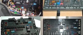
A significant part of MAZ electrical equipment is the mounting block, which contains fuses.
The device includes a multilayer printed circuit board, and if there is a short circuit in the MAZ electrical wiring and current-conducting harnesses, the unit fails. Sometimes the unit can be repaired, but more often it needs to be replaced.
When removing and installing the unit, it is important to carefully monitor compliance with the connection rules. Current-consuming devices should be connected in accordance with the Euro MAZ wiring diagram
Current-consuming devices should be connected in accordance with the Euro MAZ electrical diagram.
Do not forget that electrical diagram drawings do not reflect the actual location of elements.
The graphic representation shows the connection of the components with each other.
The nodes can be connected in series or in parallel, the components are located in the circuit in a certain order established by the manufacturer.
However, before repairing the system, we advise you to carefully study the MAZ diagram, because if the elements are connected incorrectly, a significant breakdown of the system may occur.
Connecting electrical equipment and means to facilitate starting a diesel engine
Connecting electrical equipment.
Due to the fact that the starter of a diesel engine consumes more current (compared to the starter of a carburetor engine), in order to reduce the voltage drop on the wires and ensure higher cranking speeds of the starter when starting, it is necessary to replace the wires connecting the batteries with the starter and the ground switch with thicker (section 50 mm2)
.
In addition, the wires connecting the starter relay “K7” to the starter must be replaced; these wires must have a cross-section of 4 mm2
.
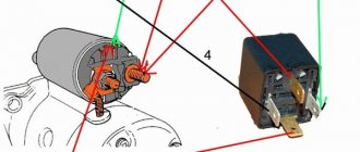
General view of the electrical circuit for connecting the motor (Fig. 12a, 12b)
.
Connection of diesel engine starting aids.
When equipping engines with glow plugs and a glow plug control unit BUSN 251.3763 (12V, manufactured by ELARA OJSC, Cheboksary), the recommended connection diagram is Fig. 12 a.
When equipping engines with glow plugs and a glow plug control unit MUSN-01 (12V, manufactured by BELKARPROM LLC, Minsk), the recommended connection diagram is Fig. 12b
.
Operating principle of the glow plug control unit (GPU):
When the ignition key is set to the IGNITION position, the unit must provide connection to the battery of four glow plugs (the unit must close the “12V” contacts), as well as a CANDLE warning lamp with a power of no more than 1.3 W.
Simultaneously with setting the ignition key to the IGNITION position, the unit must begin counting the preheating time tpp and the reliable shutdown time tno=(tpp+tco). At the end of tpp, the CANDLE indicator lamp should go out. When turning the ignition key to the STARTER position during tpp, the glow plugs must remain connected. When the ignition key is turned back to the IGNITION position, the glow plugs should turn off after tco=(120±20) s.
In this case: - if the ignition key is not turned to the STARTER position, the spark plugs must be turned off at the end of time tno; - the glow plugs must be switched on again after turning the ignition key to position “0” and re-setting it to the IGNITION position.
Operating principle of the glow plug control module (MUSN-01):
Start without heating. The units should not turn on the relay and lamp when the ignition key switch is moved from position “0” to position “I” for a time less than 2±0.5 s and then to position “II” and back to position “I” (the engine is quickly started ).
Pre-heating. After 2 ± 0.5 s from the moment the supply voltage is applied to terminal 5 (when the ignition switch is moved from position “0” to position “I”), the modules must turn on the glow plug relay and warning lamp for a preheating time equal to 20 ±2s.
Waiting for launch. After a pre-heating time of 20±2s, the modules must leave the glow plug relay switched on and go into start standby mode, switch the warning lamp to intermittent mode with a frequency of 1±0.5Hz and wait 30±2s for the engine to start
Engine starting. After starting the engine during the waiting period for starting, when the “+ST” voltage is applied to terminal 4, the modules must turn off the control lamp and work out a fixed glow time of the spark plugs, equal to 180±5 s from the moment the “+ST” voltage is removed from terminal 4. The modules must leave the relay turned on as long as the “+ST” voltage is present at terminal 4 and for 180±5 s from the moment the “+ST” voltage is removed from terminal 4.
Early launch. When the “+ST” voltage is supplied to terminal 4 during the preheating period, the modules must turn off the control lamp and work out a fixed glow time of the spark plugs, equal to 180±5 s, then turn off the relay.
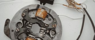
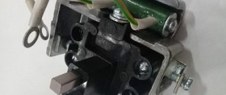
Replacement
The GAZ 53 generator is located in the front upper part of the engine, in the area of the intake manifold next to the valve cover of the 4th-8th cylinder. Replacing the part is very simple - it is easy to reach, and at the same time it has a minimum of fasteners. To remove you need:
- Disconnect the electrical circuit of the car (disconnect the terminals from the battery);
- Remove all wires from the generator;
- Unscrew the bolt securing the tension bar and turn the generator to release the belt;
- Remove the belt, unscrew the bolts and nuts of the lower fastening (only two bolts and nuts) and dismantle the generator;
- Install the new generator by performing all steps in reverse order.
Maz Zubrenok d 245 e 3 glow plug diagram
Two variants of electrical circuits for MAZ cars. All diagrams are presented in the form of small copies - to enlarge, click on the image and download to your computer.
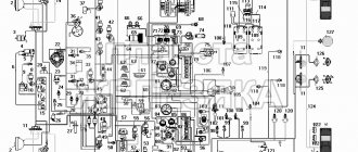
MAZ electrical circuit - option 1
1 fg1119-3711000-in-tumular fog 3 mm350b-3810000-g sensor of the oil and air pressure indicator MM-350B 4 SK-RRP127-3702000 relay-regulator assembly 5 PF101-3712000-in-fabric assembly 6,500-372432-g of the beam wires of the right sidelight 7 FG-122-3711000-V Headlight 8 PS5-3723000 Five-terminal connecting panel 9 PZhD400-1015410-B Heater control panel 10 500-3724045-B2 Wire bundle between the headlights 11 SL108-5205000-G Windshield wiper Itel electric SL-108 12 SK101-3721000 Two-tone audio signal assembly 13 500-3724086-B Wire bundle for engine heater 14 500A-3724030 Wire bundle along the spar 14 503A-3724030 Wire bundle along the spar 14 504A-3724030 Wire bundle along the spar Gerona 15 G270A-3701000-G Generator in assembly 15 SK-ST103-3708000 Starter assembly 16 SK-P39-3710000 Foot light switch 18 500-3724058-B Starter wire bundle 20 500-3724064-G Cabin and engine connection wire with ground 21 PS12-3723000 Twelve-terminal connecting panel 22 ME233 -3730000-G Heater electric motor 23 51-3723100 Wire coupling assembly 24 500-3724080-B1 Heater electric motor wire 25 PR102-3722000-B Fuse block with fuse-links assembled 26 PR102-3722000-B Fuse block with fuse with inserts 27 RS401 -3726000-G Turn signal breaker RS-401 28 500-3724010-Zh1 Main wire bundle 29 500-3724062-E Wire from batteries to starter 30 KP-118-3801000-G Instrument panel assembly 31 UK-143 Water temperature gauge 32 UK-144 Air and oil pressure indicator 33 SP-134 Speedometer 34 PP127-3713000-B Lamp sockets 35 UB-125 Fuel level indicator 36 PD20-3803000-P Turn signal indicator light 37 SK-VK26-3720000-A2 Instrument switch , windshield wipers and fog lights 38 SK-P20-3710000-A2 Switch for lampshades, heater and fuel tanks 39 PP2-3713000 Holder for low beam warning lamp. L28x1 lamp 40 500-3724073-B1 Wire from the instrument switch to the instruments 41 G-P38-3709000 Lighting switch 43 AP-109 Ammeter 44 500-3724050-G1 Wire bundle for lampshades 45 504-3724022-V Fuel level indicator wire bundle 45 504B- 3724023-B1 Fuel level indicator wire 47 500-3721080-B Signal contact device assembly 48 SK-P109-3709000-B2 Turn signal switch 49 ME302V-3730000-G Speedometer sensor 50 6TB.266.003 Plug socket for portable lamp 5 1 SK-VK318- 3704000-B Battery ground switch 52 500-3724052-B Ground wire for portable lamp socket. . 53 500-3724039-B Power cable for a portable lamp socket 54 500-3724057-D Battery jumper 55 501-8104210 Driver blower fan 56 PK201-3714010-A Cabin lighting 57 PS4-3723000-A2 Two-terminal connecting panel 58 SK-BM127- 3806600-A Fuel level indicator sensor 59 SK-VK13-3720000-B Stop signal switch 60 FP101-3716000-G Right rear light assembly 61 PS1-3723000-A2 Three-terminal connecting panel 61 PS2-3723000-A2 Four-terminal panel connecting 62 500-3724031-B1 Wire bundle of the left rear light and trailer socket 62 503A-3724032 Wire bundle of the rear lights 63 PS300-3723100 Trailer socket 64 FP101-3716000-B Left rear light assembly 65 PK201-3714010 -A Engine light 66 FYu3 -552-030 Rechargeable battery 6TST-165EMS 67 500-3724069-V Wire from the battery to the main switch 68 SK-TM100-3808000-G Water temperature indicator sensor TM-100 69 SK-RS512-3721000 Signal relay 73 500-3724058- G Bundle of starter wires (when installing a pre-heater) 75 UP101-3726000-B Side turn signal repeater 76 500-3724160 Bundle of wires for the engine assembly 77 500-3724032-G1 Bundle of wires for the right rear light 78 500-3724041-A1 Bundle of wires for the fog lights headlights
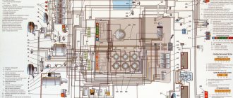
MAZ electrical circuit - option 2
Al - Fuse and relay block, A3 - Windshield wiper breaker, A6 - Turn indicator breaker, A7 - Radio, A8 - Range locking relay, BAI, BA2 - Loudspeaker, VK - Temperature sensor, VR1.VR2 - Air pressure sensor, VRZ - Sensor oil pressure, BP4.BP5 - Emergency air pressure sensor, BPI0 - Emergency oil pressure sensor, BV2 - Speedometer sensor, BV3 - Speed sensor, EKZ, EK4 - EFU spark plug, E1, E2 - Headlight, EZ, E4 - Fog light, E5,E6 - Front lamp, E7 - Lantern, E8 - License plate lamp, E9. E11 - Road train sign lamp, EI2 - Underbody lamp, E13, E14 - Side direction indicator, EI5.EI6 - Position lamp, E17, E18 - Rear lamp, E20 - Reversing lamp, E23.E24 - Cabin lamp, E25 - Courtesy lamp engine lighting, E26 - Headlight - spotlight, E28, E27 - Bed light, EK1, EK2 - Shelving light, EZO - Mirror heater, EL1. EL6 - Instrument backlight lamp, FU1 - Fuse 60 A, FU2 - Fuse 30 A, FU3-FU9 - Fuse 8 A, FU11 - Fuse 16 A, G - Generator, GBl, GB2 - Battery 6ST I90A, ON 1 - Electrical kit signals, HA2 - Pneumatic signal, KK1 - Additional resistance, KK2 - Parking brake warning lamp breaker, K1 - Starter relay, Ml - Starter, M2, MZ - Heater motor, M4 - Wiper gear motor, M8 - Washer motor, RR - Instrument cluster , P2 - Tachometer, PS - Speedometer, RP - Backlight rheostat, XSl - Main socket, XS3 - Socket, XS4 - Socket for portable lamp in the cabin, XS5, XS6 - Socket, WA - Antenna, SA1 - Starter switch, SA2 - Wiper switch , SA3 — Main light switch, SA4 — Turn signal switch, SA5 — Heater switch, SA7 — Lamp switch, SA8 — Lamp switch, SB1, SB3 — Push-button switch, SB4 — Hazard switch, SA9 — Hydraulic extraction valve switch, Push-button switches with backlight: SB5 - Fog lights, SB8 - Neutral switch, SB9 - Engine light, SB11 - Finder headlight, SB12 - Cross-axle differential, SB13 - Center differential, SB 14 - Road train lights, SB 15 - Heated mirrors, SB20 - Rack lighting , SK - Emergency temperature sensor, SLI - Fuel level sensor, SP1.SP6 - Stop signal switch, SP7 - Switch, SQ1, SQ2 - Switch.
Page 33
second gear at medium speed. When the coolant temperature reaches 60 - 70 °
Movement is carried out in gears in accordance with road conditions.
Starting a warm engine
should be done in the same order as
starting a cold engine, without necessarily disengaging the clutch.
Starting a cold engine D-245.7EZ
using glow plugs
Starting the engine using glow plugs should be done
live at temperatures from 0°
C to minus 25
°
C.
To start the engine using glow plugs, you should: — set the transmission control lever to the neutral position;
- turn on the battery switch (if the switch is installed);
- turn on the instruments by turning the instrument switch and starter key to
fixed position I;
- press the glow plug switch button and hold it down
- disengage the clutch;
— press the fuel supply control pedal
;
- after 10 - 12 seconds. after pressing the spark plug switch
glow plug, turn the instrument switch and starter key to the non-fixed position II
without releasing the glow plug switch button.
The duration of continuous operation of the starter is no more than 15 seconds. How
As soon as the engine starts to work independently, release the instrument switch and starter key, and hold the glow plug switch button in the on position until the engine reaches stable operation mode, but no more than 240 sec.
7.2.2.2. Starting a cold engine at low temperatures
At ambient temperatures below minus 25°
C (when refueling)
ke engine with low-viscosity oil) and below minus 15°
C (when filling the engine with winter oils) before starting, it is recommended to warm up the engine by pouring hot oil into the engine.
In this case, the oil should be drained from the engine into a clean container. When starting the engine, the oil must be heated to a temperature of 70 - 80 °
C and poured into the engine immediately before starting.
Before stopping the engine, let it run for 3 to 5 minutes.
first at medium and then at minimum idle speed to reduce the temperature of the coolant, oil and turbocharger.