generation Skoda Octavia A5 . It was produced in 2004, 2005, 2006, 2007, 2008, 2009, 2010, 2011, 2012 and 2013 with station wagon and liftback bodies, with both gasoline and diesel engines. In this material we will provide a description of the fuse and relay blocks of the Skoda Octavia A5 (MK2) , their locations, photographs and diagrams. We will separately highlight the fuses responsible for the cigarette lighter and washer. In conclusion, we will offer a complete electrical diagram of the car for download.
The number of elements in the block and their purpose may differ from those presented and depend on the year of manufacture, the level of equipment of the car and the country of delivery.
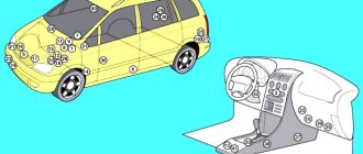
PSU installation locations and access to them
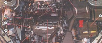
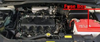
The Skoda Octavia A5, like most cars, is equipped with two safety modules: in the passenger compartment and in the engine compartment of the car. It won't take much time to get to them. If you need to inspect the fuses in the engine compartment, you just need to open the car hood and secure it.
- The safety block is located on the right near the shock absorber strut, if you stand in front of the car and look directly at it.
- Access to the fuses is as follows: you need to slide two latches on the plastic cover and pull it towards you.
- After which all protective devices and two relays are opened, providing control of the operation of the cooling fan and control of the Skoda Octavia A5 automatic transmission.
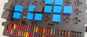
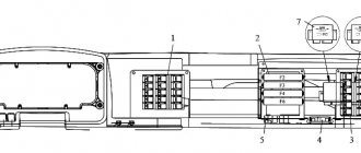
The power supply installed in the car is located near the driver in the dashboard. Once you open the driver's door, you can see a cover at the end of the front panel covering the fuse module. Using a flat screwdriver, the cover is pryed up and removed.
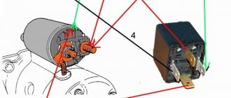
The design and principle of operation of the cigarette lighter
The device is made as follows. The cigarette lighter device is similar for all Skoda models, including Fabia, Rapid or Octavia. Inside the front panel there is a metal socket to which three wires are connected.
- Main plus (red). Comes to the battery through a protective element (fuse). Responsible for heating the internal spiral.
- Constant plus (yellow). Connected to a light filter. Responsible for the correct operation of the backlight.
- Constant minus (black). A mass with one end coming to the body of the device, and the other to the body of the car.
The Octavia A7 cigarette lighter itself is inserted into the connector, inside of which there is a metal spiral. When you press the button, the contacts close and the spiral is exposed to thermal effects. As soon as it heats up to a temperature sufficient to light a cigarette, a special thermal relay snaps the device into its initial position.
Assignment of fuses in the front panel of the Skoda Octavia A5
| № | Consumer |
| 1 | Diagnostic connector, engine control unit, fuel pump |
| 2 | ABS, ESC control unit |
| 3 | Airbags |
| 4 | Heating, air conditioning, reversing lights |
| 5 | Headlight range control unit |
| 6 | Instrument cluster, automatic transmission control unit, electromechanical power steering control unit, parking aid |
| 7-11 | Not used |
| 12 | Central locking control unit |
| 13 | Diagnostic connector, light switch |
| 14 | Automatic transmission control unit, selector lever lock |
| 15 | On-board power supply control unit - interior lamps |
| 16 | Climatronic |
| 17 | Not used |
| 18 | Rear window wiper |
| 19 | Trailer recognition control unit |
| 20 | Not used |
| 21 | Adaptive lighting, left and right sides |
| 22 | Climatronic fan |
| 23 | Front door windows |
| 24 | Cigarette lighter |
| 25 | Heated rear window, auxiliary heater and fan |
| 26 | Socket in luggage compartment |
| 27 | Fuel pump, injectors (diesel engine) |
| 28 | Head device |
| 29 | Engine control unit, crankcase ventilation heating |
| 30 | Automatic transmission control unit, Haldex |
| 31 | Vacuum pump |
| 32 | Rear door windows |
| 33 | Electric tilt-and-slide sunroof |
| 34 | Comfort system control unit |
| 35 | Alert |
| 36 | headlight washer |
| 37 | Heated front seats |
| 38 | Heated rear seats |
| 39 | Instrument cluster, wiper arm and turn signal switch |
| 40 | Heater and air conditioning fan |
| 41-42 | Not used |
| 43-45 | Towbar |
| 46 | Heated seats |
| 47 | Autonomous heating and ventilation |
| 48 | Telephone |
| 49 | Light switch |
To gain access to the mounting block located in the engine compartment and unlock the fuse box cover, move the clamps all the way down.
open lock icon will be visible on the back of the bracket/retainer . Now remove the cover. After replacing the fuse, install the cover on the fuse block and slide the locking lever all the way back. closed lock icon will be visible on the back of the bracket - the lid is locked.
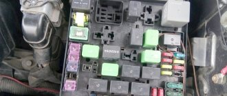
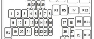
Location of fuses in the engine compartment of the Skoda Octavia A5
PURPOSE OF FUSES IN THE INSTALLATION BLOCK LOCATED IN THE ENGINE COMPARTMENT OF THE CAR
| № | Consumer |
| F1 | Not used |
| F2 | Automatic transmission control unit |
| F3 | Test lead |
| F4 | ABS valves |
| F5 | Automatic transmission control unit |
| F6 | Instrument cluster, wiper arm and turn signal switch |
| F7 | Terminal 15 power supply, starter |
| F8 | Head device |
| F9 | Not used |
| F10 | Engine control unit |
| F11 | Autonomous heating and ventilation control unit |
| F12 | Data bus control unit |
| F13 | Engine control unit |
| F14 | Ignition |
| F15 | Lambda probe, pre-glow system |
| F16 | Onboard power supply control unit, right headlight, right rear light |
| F17 | Sound signal |
| F18 | Digital Audio Processor Amplifier |
| F19 | Windshield wiper |
| F20 | Coolant pump, fuel metering valve |
| F21 | Lambda probe |
| F22 | Clutch pedal switch, brake pedal switch |
| F23 | secondary air pump, air flow meter, high pressure fuel pump |
| F24 | Canister, EGR valve, radiator fan |
| F25 | ABS pump |
| F26 | Onboard power supply control unit, left headlight, left rear light |
| F27 | Secondary air pump, pre-glow system |
| F28 | Not used |
| F29 | Terminal 30 power supply |
| F30 | Terminal Xa) |
Purpose
The Skoda Octavia A5 car has a large number of fuses, therefore, in order to have an idea of the location of a particular fuse and to know what electrical equipment it is responsible for, it is necessary to study the layout of the elements, their features and characteristics.
The safety unit in the car's interior monitors the protection of the following electrical circuits:
- ABS and ESC control unit;
- operation of airbags;
- climate control and heating system;
- automatic transmission;
- rear window wiper;
- car seat heating system.
All of the above electronic systems are controlled by five-amp protective fuses. Fuse links rated 10A monitor the operation of the car's central locking, interior and exterior lighting switches, and power unit.
To protect the electric motors of the windshield washers, headlights, and the socket installed in the luggage compartment, safety devices with a nominal value of 20A are used. As for the engine compartment protective block of the Skoda Octavia, it does not have a large number of fusible links.
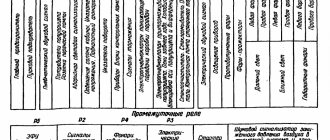
Depending on the fuse rating, the following systems protect.
| Denomination, A | What does it cover? |
| Diagnostic wiring harness, turn signal and wiper levers, engine control module, clutch pedal switch | |
| Cooling fan, exhaust gas circulation valve, secondary air pump, fuel pump | |
| Lambda probe circuit, horn, automatic transmission control unit, luggage compartment lighting, cigarette lighter | |
| Ignition, side lighting control module, right lights | |
| Higher load circuits such as starter, power terminals, ABS valves |
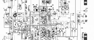
A detailed diagram of the installation of protective devices in the safety modules of the Skoda Octavia A5 is presented in the vehicle operating manual. The diagram can also be easily found on Internet sites dedicated to automotive topics.
Description of fuses for the Skoda Octavia Tour: location, diagram, price
Marking / amperageWhat it is responsible for (with description)
| F (F-1) / 20 | High beam right |
| F (F-2) / 5 | –/– left |
| F (F-3) / 10 | Front fog lamp left |
| F (F-4) / 10 | –/– right |
| F (F-5) / 20 | Heated seats, heater fan |
| F (F-6) / 30 | ABS |
| F (F-7) / 30 | Signal, trunk, cigarette lighter, transmission, diagnostic connector |
| F (F-8) / 7.5 | Fuel pump (gasoline pump) |
| F (F-9) / 10 | central locking |
| F (F-10) / 10 | Daytime Running Lights |
| F (F-11) / 10 | Air conditioning system |
| F (F-12) / 10 | Interior lighting, brake light |
| F (F-13) / 30 | ABS optional |
| F (F-14) / 30 | Reserved |
| F (F-15) / 10 | Reserved |
| F (F-16) / 15 | Reserved |
| F (F-17) / 15 | Reserved |
| F (F-18) / 10 | Heated windshield, radio, generator |
| F (F-19) / 10 | Furnace heater, electric power steering |
| F (F-20) / 10 | Electronic engine control unit, cooling system, ignition coils, fuel injectors |
| F (F-21) / 5 | Electric window drive |
| F (F-22) / 5 | Emergency crew |
| F (F-23) / 5 | Windshield wiper, front airbag |
| F (F-24) / 5 | Egnition lock |
| F (F-25) / 5 | Reverse gear |
| F (F-26) / 5 | Adsorber, oxygen flow sensor, speed sensor |
| F (F-27) / 20 | Heated rear window |
| F (F-28) / 15 | Right clearance |
| F (F-29) / 15 | Left clearance |
| F (F-30) / 20 | Rear fog lamp |
| F (F-31) / 15 | Low beam left |
| F (F-32) / 15 | –/– right |
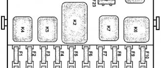
Fuses in a mounting block installed in the engine compartment of a Skoda Octavia Tour car
DesignationWhich is responsible for what/what provides
| K 1 | Who is responsible for what/what provides |
| K2 | Heated rear window |
| K 3 | Powertrain control module relay |
| K 4 | Fuel pump relay |
| K5 | Reserved |
| K 6 | Additional cooling fan relay |
| K 7 | Heated windshield (main) |
| K 8 | –/– (optional) |
| K9 | Air conditioning system |
| K 10 | Electric cooling fan |
| K11 | central locking |
| K 12 | Starter (optional) |
| K 13 | Ignition switch core contacts |
| K 14 | Reserved |
| K 15 | Windshield wiper (wipers) |
| K 16 | For headlights, high beam optics |
| K 17 | Sound notification |
The cost of a set of a new mounting block for the interior is from 2500 - 2800 rubles, for the engine compartment - from 2300 rubles. Individual modules from 200 – 250 rubles (originals), high-quality analogues from 180 rubles.
Characteristic signs of faulty fuses
- Mechanisms, equipment are inactive, the power circuit is not damaged, complete circuits, terminals, limit switches;
- The modules in the mounting block are heated, the temperature regime is unusual;
- The smell of melted plastic can be heard in the car interior and engine compartment;
- An indicator on the dashboard indicates a malfunction in the equipment;
- The car engine does not start.
Typical causes of fuse failure
- Failure to comply with the deadlines for scheduled technical inspections and replacement of worn-out elements;
- Purchase of non-original consumables (modules);
- Violation of installation technology;
- Mechanical damage to the mounting block;
- Short circuit in the electrical circuit;
- Damage to insulation, terminals, power cable ends;
- Terminal oxidation;
- Weak contact fixation;
- Formation (accumulation) of moisture and condensation, which caused a short circuit in the circuit and equipment breakdown.
Fuse color coding
| Fuse color | Maximum current |
| light brown | 5 |
| dark brown | 7,5 |
| red | 10 |
| blue | 15 |
| yellow/blue | 20 |
| white | 25 |
| green/pink | 30 |
| orange/green | 40 |
| red | 50 |
Fuse box in the passenger compartment
When you open the driver's door completely, you can see the cover at the end of the dashboard, behind which there is a cabin power supply. Opening the lid is easy; just use a flat-head screwdriver.
Engine compartment fuse box
In the Skoda Octavia car, the fuse box installed in the engine compartment near the right wing is covered with a protective cover. In order to unlock it, you need to move the latches.
By removing the cover, you can gain access to the fuses and relays that protect the components located under the hood.
The decoding of the protected electrical circuits of the on-board network of the Skoda Octavia TUR/A5 is given in the table:
Where are the fuses and block for the Skoda Octavia A5?
The fuse and relay box of the Skoda Octavia A5 is scattered in two places.
Fuse box under the hood
On some vehicles, the battery compartment cover must be removed before removing the fuse box cover.
Fuse box in the passenger compartment
Located at the end on the left side of the dashboard. Opens with a screwdriver.
This is interesting: Cleaning the Octavia throttle body
Fuse box under the hood
We open the hood and the second block is located on the upper right side of the engine. Remove the block cover by moving both brackets down and pulling the cover towards you until it moves away from the body.
In addition to fuses, the module contains relays.
RelayPurpose
| R1 | Radiator Fan Motor |
| R2 | Automatic transmission control |
Assembly
Install the fuel pump so that its outlet aligns with the recess in the top cap. Therefore, first, remove the insert with a large mesh from the ball (it is held in place by several small latches).
Install the fuel pump into the cylinder, not forgetting the O-ring in the grooves of the lower and upper parts. There is a small ring on the body of the gas receiver. Hang the screen onto the cylinder by aligning the fuel return fitting with the fitting on the screen body.
Secure the plastic cover to the 3 clamps, put on the fuel pump hose, connect the power cables and screw on the housing part with the fuel level indicator. Assembly of the remaining components of the system is carried out in the reverse order of disassembly, and does not present any difficulties.
Relay block
It is located under the instrument panel itself, behind the trim panel.
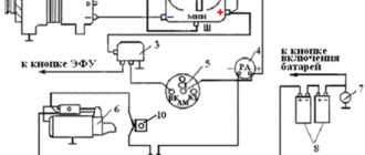
Option 1
Scheme
Designation
- B4 - supply voltage relay (30)
- B5 - rear window heating relay
- B6 - horn relay
- B7 - relay -1- glass washer pump
- B8 - relay -2- glass washer pump
- B9 - switching relay for contact X
Option 2
In this version, there is also a central control unit.
Relay block for central control unit
Scheme
Purpose
- Supply voltage relay (15) -J329-
- Relay for heated rear window -J9-
- supply voltage relay (50) -J682- / starter relay 1 -J906-
- Fuel pump relay (pressure build-up) -J643- (for engine codes BUD, CGGA, BSE, BSF, CMXA, CHGA) / fuel pump relay -J17- (for diesel engines)
- Switching relay for contact X -J59-
Additional relay block above the central control unit
Decoding
- D1 - Independent heater relay -J485- (for vehicles with an independent auxiliary heater) / relay for low heating output -J359- (for vehicles with an auxiliary resistive heater (PTC))
- D2.1 - Horn relay -J4-
- D2.2 - fuel pump relay (for engine codes BUD, CGGA, BSE, BSF, CMXA, CHGA) / - additional fuel pump relay -J832- (for engine codes CLCA, CLCB, CFHF, CFHC, CEGA)
- D3 - relay for high heating output -J360- (for vehicles with an additional resistance heater (PTC)) D3.1 - relay for the fresh air intake fan -J13- (for vehicles with an independent additional heater)
- D3.2 - Auxiliary heater fuel pump relay -J749- (for vehicles with independent auxiliary heater)
- D4 - Starter relay 2 -J907-
- D5.1 - headlight washer relay -J39
- D5.2 - relay for heating element -J925- (for engine code CAYC)
More information about the location, access, as well as a video example of removing the comfort block can be found in this video.
Is the stove not working? Some models have a thermal fuse for the stove, which is located separately.
Video example of its replacement.
Replacing fuse links
Replacement of blown fuses is carried out in the following order:
- Turn off the ignition and turn off all energy-consuming devices.
- Open the cover of the Skoda Octavia TUR/A5 fuse box, which is installed in the engine compartment or inside the dashboard.
- Determine which of the fuse links has failed. This can be seen from the molten metal insert in the slot in its body.
- Check the associated electrical circuit for short circuit or overload. Important! It is forbidden to short-circuit the wires to the car body (“ground”), checking the integrity of the wiring for a “spark”. In addition, it is not recommended to use metal tools when working with fuses - you can accidentally cause a short circuit in a working circuit.
- Take plastic tweezers (located on the inside of the lid) and use it to remove the failed fuse-link from the seat.
- Using plastic tweezers, install a new fuse-link of the same rating in the appropriate seat. Attention! When replacing, it is not allowed to use fuses of a different rating, homemade “bugs” and fuses of a different design.
- If, after replacement, the new fuse link fails again, you must contact a certified service station to check the electrical equipment using appropriate equipment.
Paid links
The easiest way to check the serviceability of the relay is to replace it with a known good one. This is what they do in workshops. Since hobbyists very rarely have a working spare relay at their disposal, the next step is recommended with the so-called switching relay, which is used, among other things, to turn on the fog and main lights.
Turn on the ignition and the corresponding switch.
First, use a voltage indicator to determine whether voltage is being applied to the corresponding positive terminal of the relay socket. To do this, connect the indicator to ground and carefully insert the other contact into the terminal.
Installing the glove box
- Hook the glove box onto the fasteners (A) (Fig. 214).
- Insert the glove box in the opposite direction of the arrow (4).
- Insert the stopper and lock it with a screwdriver in the opposite direction of the arrow (3).
- Insert the side cover in the opposite direction of the arrow (2).
- Press the side cover in the opposite direction of the arrow (1).
- Close the glove compartment.
Sources
- https://zapchasti.expert/predoxraniteli/predoxraniteli-skoda-octavia-a5.html
- https://www.avtopol-msk.ru/sxema-raspolozheniya-predoxranitelej-na-skoda.html
- https://vsepredohraniteli.ru/skoda/a5-octavija.html
- https://zapchasti.expert/predoxraniteli/predoxraniteli-skoda-octavia-tour.html
- https://fuse-box.ru/predohraniteli-i-rele-skoda-octavia-mk1-1u-1996-2010/
- https://razborov.net/shkoda/blok-predohraniteley-i-rele-skoda-oktavia-tour.html
- https://razborov.net/shkoda/predohraniteli-i-rele-skoda-octavia-a5.html
- https://angelcharlie.ru/predohraniteli-na-shkode-oktaviya-a7/
[collapse]
Check and replacement
Before removing the cigarette lighter on the Skoda Octavia A5 2016, you should check its functionality. Press the button and wait for the data for 20 seconds. If after this time the cigarette lighter has not heated up to the desired temperature or is not locked in its original position, it is necessary to carry out an inspection. Below is a table that shows when a part can be repaired and when it needs to be replaced.
| Cause of malfunction | Solution options |
| Poor contact | Bend the metal clips inside the mandrel. |
| Oxides or rust | File with contact plate. |
| Fuse blown | Replacement of cigarette lighter fuse No. F24 with a rating of 25 Amps for Skoda Octavia A5. |
| Broken wiring | Check the integrity of the cables with a multitester, solder or replace broken cables. |
| Washer casting | Replacement with a new device. |
| Cast metal spiral | Replacing a car cigarette lighter. |