Review of technical characteristics of MAZ 551605 and design features

We have written before about generators for trucks. However, today we want to look at the device connection diagram and give some operating tips.

So, the generator 4242 03.3771 has a rectifier in the voltage regulator.

Before assembly, the functionality of the installation rectifier must be checked on a bench.

Since the block consists of three elements, we advise you to inspect all the transitions.

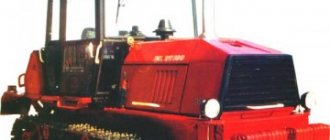
Repair and connection of the generator on MAZ trucks

The MAZ generator is a source of electricity for the vehicle's on-board network when the engine is running. The consumers are powered in parallel with the battery. The network is designed in such a way that when the generator voltage is more than 24 V, the batteries begin to charge, and less - vice versa. MAZ vehicles are equipped with units of various types, differing in power and connection method. However, their design and operating principle are the same.

Catalog of spare parts for MAZ-551605 (551605):

Our catalog contains all the spare parts used in the MAZ-551605.
Select the node you need. To make it easier to find spare parts for the MAZ-551605, you can use the quick filter. Quick Filter by nodes:

  • Body
    Cabin

    Installation of a small cabin

  • Support beam 5551-5001660
  • Cabin installation
  • Fastening the cab to the frame 551605-5000004
  • Support beam 551605-5001660
  • Installation of a large suspended cab
  • Front suspension of large cab 64226-5001700
  • Large cab rear suspension 64221-5001800
  • Installation of washer 64221-5200008-01
  • Dashboard
  • Installation of ventilation hatch 64221-5700010
  • Installation of door limiter and hinges 64221-6100006-10
  • Installing an exterior door handle and lock
  • Installing the window lifter and window lifter handle
  • Installation of glass and mirrors on a large cabin
  • Installation of glass and mirrors on a small cabin
  • Seats
      Installation and pneumatic supply of seats 64221-6800006-10
  • Installation and pneumatic supply of seats 5433-6800006
  • Installation and pneumatic supply of seats 5551-6800006-040
  • Seat 6430-6800010
  • Seat cushion and backrest 6430-6800012, 6430-6810012
  • Height adjustment mechanism 6430-6804100-010
  • Seat support with pneumatic equipment 6430-6807006-010
  • Accessories
      Installation of the platform viewing mirror 5516-8200004-01
  • Installation of berths 64221-8200010 (for a large cabin)
  • Installation of the upper berth 64221-8200011
  • Installation of handrails in the cabin 64221-8200030-10
  • Hood, fenders, radiator trim (tail)
      Installation of cladding and side panels
  • Installation of empennage on a small cockpit
  • Installation of empennage on large cockpit 64221-8400020
  • Installation of air dampers and cabin heater 64221-8100001
  • Heater 64221-8101010
  • Installation of hoses and heater control valve
  • Heater control valve
  • Cabin lift mechanism 551605-5000040-010
  • Hydraulic cylinder 64221-5003010
  • Installation of screens 551605-8400030-070 for vehicles with a small cabin
  • Installation of screens 642208-8400030-070
  • Platform
      Installation of the box 551605-8400031
  • Installation of the box 551605-8400031-020
  • Installation of platform 5516-8500002-060
  • Installation of platform V=10.3m3
  • Platform V=10.3m3
  • Installation of platform V=12.5m3
  • Platform V=12.5m3
  • Installation of platform V=15.4m3
  • Platform V=15.4m3
  • Installation of platform 650108-8500002 (-001)
  • Platform 650108-8500002
  • Installation of extension sides 650108-8500012
  • Installation of awning 551605-8500004
  • Installation of awning
  • Installation of tool box 551605-8500009
  • Installation of tool box 64229-8500009-10
  • Installation of tool box 551639-8500009-10
  • Installation of wings 5516-8500048-10
  • Installation of wings 551605-8500048-060 (-070)
  • Installation of wings 551605-8500048-020
  • Installation of subframe 5516-8600002-030
  • Installation of subframe 551605-8600002-030
  • Installation of hydraulic equipment 5516-8600005-010, (-710), (-030), (-730)
    • Engine

      Engine

      Engine mount

    • Installation of filling system and oil level control 630300-1018002
    • Heater installation
    • Installation of heater fuel lines
    • Mounting pre-heater 642290-1015001
    • Heater 6422-1015006
    • Installation of soundproofing screens 555102-1061003-040 (551605-1061002-040)
    • Installation of soundproofing screens 642208-1061003-050 (551605-1061002-050)
    • Installation of soundproofing screens 551605-1061004-040
  • Supply system
      Fuel supply lines for heater 6422-1015004
  • Fuel tank mount 551605-1101002
  • Engine shutdown drive 543208-1115002-010
  • Installation of fuel lines 551605-1104002 (with heater)
  • Installation of fuel lines (without heater)
  • Installation of fuel lines 551605-1104002-020 (from PZD 30)
  • Motor control drive 543208-1108002
  • Engine shutdown drive 551605-1115004(-700)
  • Air filter mount 551605-1109002-030
  • Air filter mount 551605-1109002-020
  • Exhaust system
      Installation of exhaust gas system 551605-1200001-004 with body heating (for gearbox 238M, 239)
  • Installation of exhaust gas system 551605-1200001-054 without body heating (for gearbox 238M, 239)
  • Installation of gas exhaust system 551605-1200001-070 (-170)
  • Installation of gas exhaust system 551605-1200001-010 (551605-1200001-110)
  • Cooling system
      Cooling System Installation
  • Radiator with casing
  • Charge air cooling system 642290-1300040, 642290-1300040-001
  • Transmission
      Clutch

      Clutch control mechanism

  • Clutch control mechanism 64229-1600005-050
  • Pedal base 64226-1602004, 64221-1602004-10
  • Pedal cylinder 6430-1602510
  • Transmission
      Installation of gearbox control drive 642205-1700002, 642208-1700002
  • Transmission control drive 543208-1700002
  • Gear shift mechanism 5336-1702200-10
  • Intermediate mechanism 551639-1703325-001
  • Switch 6430-1703800
  • Lever 64221-1703410-01
  • Lever 4370-1703410
  • Traction
  • Shank
  • Shank 543208-1703448
  • Cardan transmission
      Installation of cardan shafts
  • Rear axle
      Rear axle
  • Rear bridge. Installation of gearbox and suspension elements.
  • Rear bridge. Bridge housing
  • Rear axle gearbox
  • Rear axle gearbox. Differential
  • Drive and driven gears (spare parts kit)
  • Drive gears
  • Rear axle hub
  • Rear axle wheel reducer
  • Rear axle wheel brake
  • Rear axle brake drive
  • Bridge average
      Bridge average
  • The bridge is average. Installation of gearbox and rear shaft
  • The bridge is average. Bridge housing
  • Middle axle gearbox
  • Middle axle gearbox. Differential with gear housing
  • Middle axle gearbox. Drive gear
  • Middle axle gearbox. Differential Center
  • Middle axle gearbox. Cross-wheel differential lock
  • The bridge is average. Rear shaft
  • Middle axle wheel reducer
  • Middle axle wheel brake
  • Middle axle brake drive
  • Chassis
      Frame, bumpers and engine mudguards

      Frames 551605-2800010-024, 551605-2800010-017

  • Frames
  • Bumper mount
  • Installation of the rear bumper on MAZ-551605 with rear unloading
  • Installation of the rear bumper on MAZ-551605 with three-way unloading
  • Towing device 5336-2707212-11
  • Installation of side guard 551605-2800040
  • Installation of side guard 551605-2800040-010
  • Installation of side guard 551605-2800040-020
  • Suspension
      Front suspension 551605-2900001-010
  • Balancer suspension 551605-2900002-030
  • Balancer suspension 551605-2900002-030
  • Front axle
      Front axle
  • Front axle
  • Front wheel hub
  • Front axle beam with knuckles
  • Tie rod
  • Longitudinal rod 5551-3003010-30
  • Wheels
      Installation of spare wheel 551605-3100001(-700)
  • Installing a spare wheel 551607-3100001-40, 5516-3100001-40
  • Installation of spare wheel 551605-3100001-010(-710)
  • Installation of rear wheels 5516-3100002-030(-730)
  • Installation of front wheels 551607-3100005-10, 5516-3100005-10
  • Wheel, camera and tire 551607-3101011-10, 5516-3101011-10
  • Control mechanisms
      Steering

      Installation of the steering column and steering mechanism 630300-3400001-010(-710), 551603-3400001-010 (-710)

  • Steering installation 630300-3400001-010 (-710), 551603-3400001-010 (-710)
  • Pump 630300-3407010 (-700)
  • Pump 543240-3407010 (-700)
  • Power steering power cylinder 6422-3405004
  • Steering gear 64221-3400008-02
  • Bracket with column 64221-3403008
  • Distributor 5336-3416010-01
  • Oil tank 64221-3410008
  • Lower shaft 5336-344450-11
  • Brakes
      Front wheel brake
  • Wheel brake
  • Adjustment lever
  • Installation of pneumatic compressor 642208-3500014 (-700)
  • Regeneration receiver 64226-3513015
  • Installation of receivers 551605-3513004
  • Installation of connecting fittings on receivers
  • Brake valve 64221-3514108-010
  • Brake valve drive pedal
  • Brake valve mount 64221-3514004-20
  • Brake valve mount 64221-3514004-20
  • Four-circuit valve mounting 551605-3515002
  • Installation of relay valve 543403-3518004-010
  • Installation of relay valve 643008-3518004
  • Brake chamber mounting 643008-3519001
  • Brake chamber mount 5440-3519002-10 (on the rear axle)
  • Brake chamber mount 551605-3519003 (on the middle axle)
  • Pneumatic outlets for trailer 63031-3521004
  • Trailer Valve Installation 642208-3522005
  • Brake force regulator mount 64221-3533002-02
  • Air dryer installation 650108-3536004
  • Parking and engine brake drive 5516-3537004
  • Parking and engine brake drive 64255-3537004
  • Engine stop cylinder 543205-3570004
  • Engine stop cylinder 642208-3570004
  • Installation of proportional valve connecting fittings
  • Installation of front modulators and connecting fittings
  • Installation of rear modulators and connecting fittings
  • Connection for repairing damaged pipelines
  • Hoses
  • Electrical equipment
      Electrical equipment

      Installation of road train lights 64221-3700099-10

  • Installation of headlights 64221-3711029-010, 64221-3711030-010
  • Installation of batteries 551605-3700008-071 (-771)
  • Installation of rear lights 551605-3700009 (-700)
  • Installation of sockets 63031-3700015
  • Electrical installation of fan clutch 543208-37000073 (-700)
  • Windshield wiper installation 64221-3700041-010
  • Wiper drive 64221-5205500-010
  • Instrument panel 551605-3805010 (-700)
  • Instrument panel 6303-3805010
  • Installation of additional instrument panel 64229-3805012
  • Fuse and relay panel 543240-3722014 (-700)
  • Installation of switching equipment
  • Installation and sealing of the speedometer 551605-3800004 (-700)
  • Installation and sealing of tachograph 543203-3800005 (-700)
  • Installation of electrical equipment EFU 642208-3700124 (-700)
  • Installation of electrical equipment of the heater 630305-3700085
  • Installation of electrical equipment PZD 5434-3700049-10
  • Installing a fog light
  • Installing a side turn signal
  • Installing a bed light
  • Location of connectors and electrical components on the YaMZ-238DE2, YaMZ-7511 engine
  • Location of connectors and electrical equipment elements at the YaMZ-238M gearbox, YaMZ-239 gearbox, 9JS135A gearbox
  • Location of connectors and elements of electrical equipment for controlling the raising and lowering of the platform, and the reverse sound signal
  • Arrangement of connectors and elements of electrical equipment on a small cab of dump trucks with rear unloading
  • Arrangement of connectors and elements of electrical equipment on a small cabin of dump trucks with three-way unloading
  • Arrangement of connectors and elements of electrical equipment on a large cab of dump trucks with three-sided (side) unloading
  • Location of connectors and electrical components on the large cab of rear dump trucks and dump chassis
  • Location of connectors and electrical components on the chassis of vehicles without a platform
  • Location of connectors and electrical equipment elements on the chassis of dump trucks with three-way unloading
  • Location of connectors and electrical components on the chassis of dump trucks with rear unloading and a bucket platform
  • Location of connectors and electrical components on the chassis of dump trucks with rear unloading and a platform with a tailgate
  • Electrical equipment. List of elements
  • Location of electronic system elements in the cabin of a MAZ-551605 vehicle without a trailer
  • Arrangement of electronic system elements in the cabin of a MAZ-551605 vehicle with a trailer
  • Installation of ABS electrical equipment elements on MAZ-551605 vehicles
  • Installation of an electronic ABS unit on cars
  • Car relay and fuse panel
  • Optional equipment
      Accessories

      Installing Accessories 5516-3900011

  • Installation of wheel chocks 53373-3900037
  • Installation of wheel chocks 551605-3900037
  • Installation of fire extinguisher 5516-3910040
  • Power take-off
      Power supply to power take-off 551605-4200007-032
  • Installation of power take-off and pump
  • Power take-off 503-4202010-B
  • Pump with fittings 551605-8604010
  • Power take-off 64228-4202010
  • Hydraulic equipment
      Hydraulic cylinder 55165-8603510
  • Installation of hydraulic equipment 551605-8600005-025, (-035), (-725), (-735)
  • Installation of cylinder and valve 551605-8603500-025 (-725)
  • Hydraulic cylinder 6501-8603510
  • Valve 555102-8607300
  • Installation of hydraulic equipment 551605-8600005-032, (-732)
  • Pump with fittings 64228-8604010-032 (-732)
  • Installation of hydraulic equipment 551605-8600005-042, (-742)
  • Installation of oil tank 551605-8600034-025
  • Spare parts diagrams and components are presented on the website for reference purposes! We do not sell all spare parts for MAZ-551605 presented in this list, but many of them.

    Device

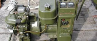
    The generating set (GS) is a three-phase synchronous machine with excitation from an external power source and a rectifier unit. To control the output voltage and maintain it within specified limits, an integrated voltage regulator is installed.

    The operating principle of the generator is based on the phenomenon of electromagnetic induction. The rotating magnetic field of the rotor, crossing the stator windings, induces an EMF in them, which is connected to the load through the rectifier unit. The main elements of the generator are:

    • rotor;
    • stator;
    • front and back covers with built-in rectifier;
    • brush holders with integral voltage regulator;
    • fan pulley and impeller.

    The generator rotor is a shaft made of electrical steel, on which an excitation winding (inductor) is wound. Power is supplied to it through 2 contact rings installed on the side of the back cover. 12 beak-shaped magnets are pressed onto the shaft. Ball bearings are installed at both ends of the rotor.

    The stator winding is three-phase and consists of 36 coils. Each phase has 12 series-connected windings located in the stator slots and offset from one another by 120°. The electrical connection of the poles is made according to the “star” principle. The phase output terminals are connected to the rectifier unit.

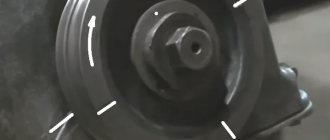
    A rectifier unit, voltage regulator and brush holders are installed on the back cover of the generator. The body elements are cast from aluminum alloy. In the center of each cover there is a place for installing a bearing. The fan impeller is installed on the rear end of the shaft, held from turning by a key and secured with a nut. In a similar way, a double-groove pulley is attached to the armature shaft in the front part of the GU. The design of generators of different models of MAZ cars is the same and differs only in the way they are connected to the network.

    How to connect a MAZ generator

    The proper operation of on-board network devices largely depends on the correct connection of the control unit. If MAZs of the famous 500th series could operate using only one battery, then this is impossible on modern cars. The presence of a large number of electronic devices and gadgets has increased the power consumption of the network and requires an additional power source.

    The connection diagram for the MAZ generator depends on its type. However, in all cases, the inductor must be powered and the load must be connected, which is the on-board network and battery. The connection terminals are located on the back cover and are designated by the letters “W” and “+D” for the field winding and “+” for the load (ignition switch).

    The output of one of the phases of the PG is connected to the tachometer. Terminal “B” is connected to the generator blocking relay and the battery charge indicator lamp. The connection circuit is simple, but requires attention when performing work.

    Technical component

    Technical characteristics of MAZ-551605-280:

    Average fuel consumption
    Wheel formula6*4
    Maximum engine power243 l. s.s.
    Pressure exerted on the front axle7,000 kg
    Rear Cart Load26,000 kg
    Curb weight13,000 kg
    Maximum weight of transported cargo20,000 kg
    Loading platform volume15.4 m³
    Power unit modelYaMZ-238DE2
    International environmental standardEuro 2
    Number of gears8
    Drive wheel ratio6,59
    Wheel size12.00R20
    Fuel tank volume350 l
    Gross vehicle weight, kg33 000
    Wheelbase3.9+1.4 m
    dimensions8.13*2.5*3.14 m

    Parameters and indicators of MAZ-551605-271:

    Total number of wheels6
    Number of driving wheel mechanisms4
    Front axle pressure7,000 kg
    Load on the rear bogie26,000 kg
    Curb weight13,000 kg
    Motor modelYaMZ-238DE2
    Environmental standardEuro 2
    Type of fuel usedDiesel
    Gearbox modelYaMZ-238M
    Gearbox typeMechanical
    Number of gears8
    Gear ratio6,59
    Tire size12.00R20
    Fuel container350 l
    Maximum driving speed92 km/h
    Load capacity20,000 kg
    Weight33,000 kg

    Malfunctions

    GU breakdowns can occur in both electrical and mechanical parts. Signs of defects are the absence of charging current when the car engine is running or a voltage drop when a large load is turned on. In the first case, the malfunction is most often associated with a lack of excitation current or failure of the voltage regulator, and in the second, with slipping of the drive belt.

    All defects can be eliminated, except those associated with damage to the stator and rotor windings. In this case, a unit replacement of the mechanism is necessary.

    Repair

    To eliminate malfunctions, the power unit must be dismantled from its original location. The fault can only be identified by disassembling the device. The result should be 2 halves: the first, consisting of the front cover with a pulley and armature, the second - from the rear cover and stator. To carry out checks and measurements, the stator winding is disconnected from the rectifier unit. The coils are checked for integrity and breakdown to the housing.

    To measure the resistance of the windings, a tester is used, and a 100 V megohmmeter is used to measure short circuits to the housing.

    The use of 220 V indicator lamps is prohibited due to safety requirements. The field winding is checked in the same way. Damaged elements must be replaced.

    Rating
    ( 2 ratings, average 4.5 out of 5 )
    Did you like the article? Share with friends:
    For any suggestions regarding the site: [email protected]
    Для любых предложений по сайту: [email protected]